
Abstract
Lengthening the femur with an external fixator is commonly practised for a wide variety of pathologies. This technical report includes tips derived from observation and experience in a busy limb reconstruction unit. It focuses on the use of a rail fixator, although some of the descriptions are applicable to lengthening by circular fixators.
Introduction
Lengthening the femur with an external fixator is commonly practised for a wide variety of pathologies. This technical report includes tips derived from observation and experience in a busy limb reconstruction unit. It focuses on the use of a rail fixator, although some of the descriptions are applicable to lengthening by circular fixators.
Sites for lengthening
The usual chosen sites of femoral osteotomy for lengthening are metaphyseal regions, often the subtrochanteric or supracondylar areas. These areas are predictably good at regenerate formation and offer a greater bone width in comparison with the diaphysis. Diaphyseal lengthening is also carried out but adjustments to the lengthening rate (0.75 mm per day is preferable to the usual 1.0 mm per day) are needed in order to compensate for slower regenerate formation.
Issues in femoral lengthening
Muscle tension
The muscles acting across the femur are responsible for many of the problems that arise during lengthening. The large quadriceps, gluteal muscles, hamstrings and adductors can influence the progress of lengthening; tension created during lengthening produces pain, reduces movement across joints and deforms the regenerate column of bone. Understanding the problems that arise during lengthening and adjusting the surgical strategy to minimise their impact underpins a successful lengthening.
Control of segments
Many devices are available for femoral lengthening. Circular and monolateral external fixators are used most commonly, although intramedullary devices are also popular for skeletally mature patients. Irrespective of the device used, close adherence to the principles of lengthening by Ilizarov [1, 2], De Bastiani [3] and others is important. In particular:
-
(1)
The osteotomy is low energy and preserves the soft tissue envelope and vascularity
-
(2)
The fixation applied to hold the segments created by osteotomy is stable
-
(3)
A latency period follows the osteotomy
-
(4)
The distraction rate and rhythm is appropriate to the level and type of bone divided.
The stability provided through the fixation device (irrespective of whether this is external or internal) is not static. As lengthening proceeds, the distance between the segments increases and control becomes increasingly difficult. The challenge to maintain bone alignment during lengthening is related to this increasing distance, the muscle tension generated, the location of the osteotomy and stability provided by the fixation device.
General recommendations
When using a rail fixator for femoral lengthening, several important principles can be used to ensure optimal control of the bone segments. Using the rail fixator from Orthofix as an example (Orthofix LRS, Verona, Italy), these can be summarised as follows:
-
(a)
There should be at least three pins per segment of bone held by the fixator. The pins should be spread widely across the length of the clamp, usually in the first, third and fifth holes (Figs. 1, 2). If the bone segment to be held is short, it is possible to use the second, fourth and fifth holes but this reduces the spread of the screws from 5 cm to 4 cm.
Fig. 1 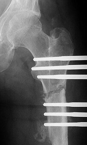
The spread of pins in each clamp on either side of the osteotomy is suboptimal. They are too close together, thereby reducing control over the segment of femur
Fig. 2 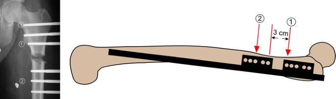
The X-ray image shows pins located in thefirst,third andfifth seats of the clamp with optimal spread. The order of pin insertion, in particular with regard to ‘reference’ pins, is marked (1) and (2). Pin (1) is placed just below the ‘equator’ of the lesser trochanter. The most proximal pin (5) is unicortical but a hydroxyapatite-coated screw is used to ensure satisfactory bone hold. In order to maintain control of the femoral segments as the lengthening proceeds, it is recommended that the clamps are situated about 3 cm apart
-
(b)
The two pins that straddle the proposed osteotomy site should be less than 3 cm apart. This means positioning the two clamps about 2.5 cm from each other (Fig. 2). This ensures that as lengthening progresses and the clamp–clamp distance increases, stability is maintained.
-
(c)
Each pin should be inserted across the diameter of the bone and avoid eccentric (intracortical) insertion. Attention to this detail ensures the threaded part of the half-pin engages the widest part of the bone and is thus better able to control it. However, whilst this is eminently possible when applying a straight rail to a straight bone, the sagittal profile of the femur is curved and some screws will inevitably not lie across the diameter of the bone. The technique below, which describes the order of screw insertion and centralising the position, will optimise the spread of screws despite this anatomical issue.
-
(d)
Bone is living material, and it is easy to forget that local temperatures of 50°C, when maintained for longer than 1 min, will kill this hard tissue [4]. Thermal necrosis produced at the time of drilling is a cause of ring sequestra from local pin site infections. Drilling should always be with a sharp drill, using a stop–start technique with slow drill speeds to reduce long periods of constant fast speed drilling and always with drill cooling using normal saline [5]. Whenever the drill flutes become full, the drill should be extracted, the flutes cleared and drilling recommenced.
-
(e)
Hydroxyapatite-coated pins should be considered mandatory when external fixators are used in lengthening. The improved extraction torque and resistance to loosening contribute to the better hold on the individual bone segments achieved by the fixator, thereby lessening the risk of loss of control and subsequent deformity [6].


Anatomical or mechanical axis lengthening
In the tibia, where the mechanical and anatomical axes are parallel, there is no debate over placing the fixator rail parallel to either limb axis. In contrast, the anatomical and mechanical axes of the femur are not parallel. In theory, it is preferable to place the fixator rail parallel to the mechanical axis so that lengthening does not induce a displacement of this axis. Lengthening along the anatomical axis in the femur produces a medialisation of the knee and consequently, a lateral shift of the mechanical axis. In clinical practice, this effect only becomes significant if there was a preexisting valgus deformity in the femur and therefore a lateral shift of the mechanical axis already present; the lengthening along the anatomical axis will then accentuate this lateral shift of the axis and make it clinically significant. In the absence of this problem, femoral lengthening can be performed along the anatomical axis.
General aftercare
There are many pin site care regimes and some evidence supporting specific ones. We have found the regime advocated by the Russian Ilizarov Scientific Centre for Restorative Traumatology and Orthopaedics (RISC RTO) in Kurgan, Siberia to be better than that of daily cleaning with Normal saline or water [7].
If hydroxyapatite screws are used, we recommend limiting weight bearing to 20–30% bodyweight in the first 6 weeks after surgery to permit bonding between the screws and bone. Thereafter, the patient is permitted to bear weight as tolerated; this functional loading is known to increase the blood supply through the limb [8].
Physiotherapy regimes assist in the gradual and supervised return of weight bearing as well as maintenance of joint movement range and control. Lengthening for congenital pathologies deserves special mention; the soft tissues are most resistant to lengthening, and it is advisable to keep the target lengthening to less than 15% of the original length of the limb. Muscle releases are usually necessary for this group of conditions.
Subtrochanteric femoral lengthening
Advantages
Regenerate quality
This area in the proximal femur has an excellent blood supply from anastomoses between branches of the medial and lateral circumflex femoral vessels. Consequently, regenerate formation is usually good, provided the general principles of osteotomy are followed.
Minimal interference with knee ROM
As the site of lengthening is proximal, there is less interference with knee joint movement distally. However, if the insertion of gluteus maximus inserts into the distal segment created by the osteotomy, the increasing tension in this muscle from lengthening may produce an abduction contracture at the hip. Awareness of this possibility should be shared with the physical therapists who may notice the patient walking with a pelvic obliquity, despite achieving leg length equality. Gradual stretching of the gluteus maximus will reduce the problem.
Disadvantages
Varus and procurvatum control
Gradual development of varus and procurvatum occurs with proximal femoral lengthening, irrespective of the type of external fixator device used. With circular systems, the possibility of correction of the deformity after lengthening is useful. Some monolateral rail systems also posses adjustable clamps (e.g. the micrometric swivel clamp of the Orthofix LRS) that allow the correction of the varus component to be reduced but, being a device applied in the coronal plane, correction of procurvatum is more difficult. In general, this deformity is not a clinically significant issue in subtrochanteric lengthening if the target lengthening is kept 5–6 cm. Should the surgeon wish to achieve a greater length using a monolateral device, consideration should then be given for bifocal femoral lengthening where it is possible to achieve 5 cm of lengthening at each osteotomy site. Bifocal femoral lengthening should not be used for lengthening for congenital pathologies (especially longitudinal deficiency of the femur) as the tension created in the soft tissues will become excessive.
Osteotomy technically more difficult
The cortical thickness of the femur rapidly increases distal to the lesser trochanter. This can sometimes make the osteotomy more difficult and predispose to a greater likelihood of crack propagation to the nearest pin. Due care and attention are needed, and tips for creating a ‘clean’ osteotomy are provided below.
Technique
Ensuring central placement of pins across diameter of the bone
Pin placement across the diameter of the femur maximises the hold of that segment. After the skin and fascia incision and blunt dissection to the near cortex, the drill tip (sheathed in the screw and drill guides that act as the soft tissue guard) can be used as a trocar tip to determine the anterior and posterior limits of the femoral width. The drill is then placed in the middle of these two limits. A check is performed by X-ray: if the drill tip is central, the tip will just lie against the cortex and its shadow will not overlap the femur (Fig. 3).

By a combination of feeling the antero-posterior width of the femur using the drill tip and X-ray checks (which confirm the tip of the drill bit just abuts the lateral cortex), the surgeon can ensure the drilling passes across the widest diameter of the bone
Order of pin insertion
It is helpful to insert the most distal pin of the proximal clamp first (Fig. 2). This can be done without the need of the template or rail but using X-ray as a guide to ensure central placement across the diameter of the bone and at right angles to the anatomical axis. I have found it useful to use the lesser trochanter as a landmark; insert this pin just distal to the ‘equator’ of the profile of the lesser trochanter. This location will ensure there is sufficient space for subsequent placement of another two pins in the proximal clamp in the third and fifth seats of the clamp.
After the insertion of this first ‘reference screw’, apply a rail with its two template clamps (assembled about 3 cm apart) to femur. The first screw should be placed in the first seat (next to the proposed osteotomy) in the proximal clamp. In the Orthofix system, the screws are held in the template clamps with their respective screw guides. Next, incise the skin corresponding to the third seat of the distal clamp template. Divide the fascia percutaneously and bluntly dissect a track down to the lateral cortex of the femur. Using the drill tip in its drill and screw guides, locate the central part of the femur and drill across at right angles to the axis of the femur. This is the location of the second ‘reference pin’. When both reference pins are securely held in their respective screw guides in the proximal and distal clamp templates, insertion of the remaining screws is a mechanical process as the position of the rail against the femur would have been determined by first two reference screws. Place the remaining screws in the template seats so that the first, third and fifth positions are filled. It is important to note that the most proximal screw of the proximal clamp is likely to be at a level where the second cortex for the screw will be across the femoral neck; perforating the femoral neck with a screw may leave the patient at risk of a femoral neck fracture after fixator removal. My recommendation is that the drill (4.8 mm in the Orthofix system) is advanced across this level by 2–3 cm, and the screw is inserted in a unicortical fashion until it abuts against the femoral calcar. This creates a reasonable level of radial preload by the screw in the cancellous bone, and bonding will occur between it and the HA coating of the screw (Fig. 2).
Osteotomy technique
There are many acceptable techniques and, as long as the principles are followed, regenerate formation will not be compromised. My preference is for a percutaneous technique, performed through a 2 cm incision. The rail is removed to give clear access to the space between the two groups of screws. The incision is either longitudinal or transverse and the fascial incision likewise. Blunt dissection creates a track down to bone. No attempt is made to elevate the periosteum. Three drill passes (4.8 mm drills in adults and 3.5 mm in children) are made across the diameter of the bone in evenly spread directions. A 10–15-mm wide osteotome is then used to create a complete division of the lateral half of the circumference of the femur before the blade is advanced across the diameter of the bone (Fig. 4). The osteotome is then advanced across the central portion to divide the far cortex. Completion of the osteotomy is by osteoclasis, often through using a spanner on the handle of the osteotome and twisting it. Confirmation of completion of the osteotomy is through the manipulation of the two segments and by X-ray. The rail is then reapplied (with the definitive clamps replacing the templates) and the position of the clamps adjusted to ensure correct alignment and contact of the two femoral segments at the osteotomy site.

Several techniques of osteotomy have been described. In this technique, not more than 3 drill passes are made (6 holes in the femur created). This is then followed by passing a narrow osteotome that divides the lateral half of the cortical circumference first. Only then is the far cortex divided and the osteotomy completed by osteoclasis
Supracondylar femoral lengthening
Advantages
Regenerate width and quality
The supracondylar region is wider than the subtrochanteric and provides a larger area for regenerate formation. A clean division of the bone (without crack propagation into a screw hole) is usually more predictable as cortical thinning towards the metaphysis occurs over a greater length than is the case in the proximal femur.
Combination with deformity correction
Not infrequently, leg length inequality arises in children because of damage to the distal femoral growth plate. This may arise from infection, fracture or bone disease. These pathologies may also cause deformities around the knee; supracondylar femoral lengthening with a rail fixator will provide the surgeon an opportunity to acutely correct the deformity through the osteotomy and address the leg length inequality (Fig. 5).

A growth plate disturbance of the distal left femur causes deformity and length inequality. A supracondylar osteotomy with acute correction of deformity followed by lengthening corrects both problems
Disadvantages
Interference with knee ROM
The most important disadvantage of distal femoral lengthening is interference with knee movement range. This arises because of quadriceps transfixation and tethering of the iliotibial band. It is inevitable that some movement is lost, albeit temporarily, during the period of lengthening. This can be minimised if the pins inserted into the distal segment are placed transfixing the quadriceps muscle in flexion. This is more useful than iliotibial band and fascial division between the two clamps, a technique previously recommended for maintaining knee flexion.
Technique
Order of pin insertion
The same technique for locating the maximal width of the femur before drilling across is used. This ensures central placement of the pin across the diameter of the femur. Start by marking out the location of the proposed osteotomy. This is in the supracondylar region, with at least 10 cm of femur available distal to the proposed osteotomy level; this will enable 3 pins to be inserted in the first, third and fifth seats of the distal template clamp. Have an assistant flex the knee to greater than 90° and mark out the skin insertion point. Make the incision through skin and fascia and perform blunt dissection with the knee flexed. Only when the drill, drill and screw guides are passed down to bone and held, is the knee extended then and placed on the operating table. This ensures that the lateral aspect of quadriceps (including the iliotibial tract) is transfixed in flexion (Fig. 6). The drill tip position can then be adjusted with X-ray checks to ensure it is optimum before drilling, making sure at all times that it remains on the bone surface and thus keeping the transfixation of the muscles in flexion. Should the screw guides slip off bone, especially when the drill tip is withdrawn to allow screw insertion, repeat the flexion manoeuvre and insert the screw with the assistant holding the knee flexed. Insert the first pin using this knee flexion technique 1.5 cm proximal to the proposed osteotomy level, checking that it is placed at right angles to the anatomical axis and across the central diameter of the femur. Attach the rail and two templates, seating this screw in the most distal position of the proximal clamp. The two clamp templates are again separated by a distance of 3 cm as was the case in the subtrochanteric region. Insert the second reference screw in the third seat of the distal template clamp, centring across the diameter of the bone and at right angles to the anatomical axis. Again, ensure the knee flexion technique is carried out. Subsequent screw insertion is mechanical, but it is important that all screws are inserted with the knee flexion technique. Bicortical purchase for all screws is important, and HA screws should be used. If using tapered screws from the Osteotite system (Orthofix SRL, Verona, Italy), it may be advantageous to drill the near cortex with a 4.8-mm drill and the far cortex with a 3.2-mm drill only in metaphyseal bone. This increases the radial preload of these tapered screws in cancellous bone. This double drill technique must not be used in diaphyseal bone. At the end of the procedure and with all screws in place, the knee will flex passively without any resistance if the leg is carried over the edge of the table. No manipulation of the knee is required. This confirms transfixation of quadriceps and the iliotibial tract in flexion.

Keeping the knee flexed to beyond 90° prior to drill passage ensures the quadriceps and iliotibial tract are transfixed in flexion. This reduces the interference to knee flexion movements after surgery
The osteotomy for lengthening (with or without acute correction of deformity) is performed in the same manner as described for the subtrochanteric region.
Bifocal femoral lengthening
Advantages
Shorter healing time
The bone healing index (the period for which external fixation is required divided by total gain in length—expressed as days per cm) is not a constant figure. It decreases with increasing length at a single osteotomy site [9]; even a simple osteotomy without lengthening will incur a healing time and therefore generate an index. However, with bifocal lengthening, two sites are being lengthened simultaneously and each site consolidates independently. Therefore, twice the length of bone is generated within the same period of external fixation and thus the bone healing index is halved.
Greater potential for total length gain and prevention of deformity
As a consequence of the biomechanics of maintaining control over the alignment of the separating segments of bone, it was advised that most single site lengthenings should be kept to less than 5–6 cm. In order to achieve greater length gains, a double level lengthening offers the potential for 10–12 cm increase. This would be with control over the alignment of the bone segments. Even with a 7 cm lengthening, two 3.5 cm lengthening sites would be an attractive option—a shorter period in external fixation and greater control over alignment—provided there is sufficient space to perform two osteotomies and have three clamps with a total of 9 screws (three in each clamp).
Disadvantages
Soft tissue problems
Whilst each osteotomy site may be generating new bone at 1 mm per day, the overall effect on soft tissue tension is twice that. Soft tissues tend to prefer a slower rate of distraction and may be at risk of increased fibrosis if distracted at a faster rate [10–12]. Higher peak forces may also be generated during the lengthening process, particularly so in congenitally short limbs. These factors account for greater problems with maintaining joint movement and contractures. Therefore, bifocal lengthening in the femur should not be used as a technique for congenitally short limbs.
Pain
The higher peak forces and accompanying muscle tension generated by bifocal lengthening produce greater pain. This may have a negative effect on the ability to cope with physiotherapy and rehabilitation exercises.
Technique
Curved sagittal profile
The profile of the femur in lateral view is curved, and inserting a series of screws set in line on a straight rail is difficult (Fig. 7a). Several strategies have been described for overcoming this problem. The sagittal curvature of the femur also varies between individuals; sometimes, it is possible to place all screws comfortably in line without great adjustment to technique. Usually, this is only possible when the degree of curvature is small and the femur large.

The curved sagittal profile of the femur can make it difficult to fit a straight rail. A sandwich (double tier) clamp on the rail is able to solve this problem. The order of pin insertion is marked
Order of pin insertion
If a bifocal lengthening is planned with the osteotomies in the subtrochanteric and supracondylar regions, the following sequence of screw insertion may minimise the problem of the curved sagittal profile. Use of a sandwich clamp in the middle is needed (Fig. 7b). The first screw inserted is proximal, just distal to the ‘equator’ of the lesser trochanter. The rail is then applied to this screw with the 3 template clamps positioned appropriately. The middle template is the sandwich template clamp. It is positioned to lie in between the proximal and distal template clamps and is thus a compromise between stability and convenience. The distal template is positioned in the usual position for a supracondylar osteotomy. If the femur is unusually long, the middle template clamp can be sited 3 cm distal to the proximal (as in subtrochanteric lengthening) and an additional template clamp can be sited 3 cm proximal to the distal template. This arrangement of 4 template clamps is not often needed but provides additional stability for lengthening in long femora (Fig. 8a, b).

a In long femurs, it is advantageous to use four clamps. This ensures good control of the middle segment by the spread of the pins. In this example, proximal lengthening is combined with distal acute correction of a valgus deformity, b Lateral view of the case in a where a sandwich clamp is used to ensure good purchase of the pins either on or near to the mid-axis of the femur
The second reference screw is inserted through the third seat of the distal template clamp. If centralised across the diameter of the femur, this sets the rail into a position that is the most useful compromise to the curved sagittal profile. The third screw is inserted in the third seat of the middle template—choice over which tier of the sandwich template is used for screw insertion is determined intraoperatively—the position of the screw seat that provides the most central location across the diameter of the femur is chosen (Fig. 8b). Additional screw placement can be done so as to fill the first and fifth seats of the distal template clamp, third and fifth seats of the proximal and first and fifth seats of the middle template.
General tips on use of bifocal femoral lengthening
Bifocal lengthening is used when the target lengthening is in excess of 5–6 cm at a single osteotomy site. This is to avoid deformity that may occur when a greater amount of lengthening is attempted from a single site. The surgeon should be aware and anticipate the higher rate of soft tissue problems and greater pain with bifocal lengthening. Accordingly, bifocal lengthening should be used judiciously and not for congenital longitudinal deficiency of the femur.
Conclusion
The rationale and technique for femoral lengthening with a monolateral rail fixator have been described. The technique has evolved over regular use of the device in a busy limb reconstruction unit in Liverpool. The Orthofix LRS system was used to illustrate surgical tips. As with all types of devices used for femoral lengthening, the surgeon needs to appreciate the strengths and weaknesses of each and use the most appropriate. The monolateral rail fixator has strong appeal for patients who wish not to be encumbered with a circular fixator on the thigh; however, the facility for deformity correction after lengthening is less and as such the surgical planning technique and after care have to anticipate this factor. Nonetheless, a monolateral rail fixator is probably suitable for the majority of cases in need of femoral lengthening encountered in clinical practice.
References
Ilizarov GA (1989) The tension-stress effect on the genesis and growth of tissues: Part II. The influence of the rate and frequency of distraction. Clin Orthop Relat Res 239:263–285
Ilizarov GA (1989) The tension-stress effect on the genesis and growth of tissues: Part I. The influence of the rate and frequency of distraction. Clin Orthop Relat Res 239:249–281
De Bastiani G et al (1987) Limb lengthening by callus distraction (callotasis). J Pediatr Orthop 7(2):129–134
Eriksson RA, Albrektsson T, Magnusson B (1984) Assessment of bone viability after heat trauma: a histological, histochemical and vital microscopic study in the rabbit. J Plast Surg Hand Surg 18(3):261–268
Augustin G et al (2008) Thermal osteonecrosis and bone drilling parameters revisited. Arch Orthop Trauma Surg 128(1):71–77
Moroni A et al (2005) Hydroxyapatite-coated external fixation pins. Expert Rev Med Devices 2(4):465–471
Davies R, Holt N, Nayagam S (2005) The care of pin sites with external fixation. J Bone Joint Surg Br 87-B(5):716–719
Kroese AJ (1977) The contribution of muscle and skin circulation to reactive hyperaemia in the human lower limb. Vasa 6(1):9–14
Fischgrund J, Paley D, Suter C (1994) Variables affecting time to bone healing during limb lengthening. Clin Orthop Relat Res 301:31–37
Barker, KL, Simpson AH , Lamb SE (2001) Loss of knee range of motion in leg lengthening. J Orthop Sports Phys Ther 31(5): 238–244 (discussion 245–246)
Simpson AH et al (1995) The response of muscle to leg lengthening. J Bone Joint Surg Br 77(4):630–636
Simpson AH et al (1996) The forces which develop in the tissues during leg lengthening. A clinical study. J Bone Joint Surg Br 78(6):979–983
Open Access
This article is distributed under the terms of the Creative Commons Attribution Noncommercial License which permits any noncommercial use, distribution, and reproduction in any medium, provided the original author(s) and source are credited.
Author information
Authors and Affiliations
Corresponding author
Rights and permissions
Open Access This article is distributed under the terms of the Creative Commons Attribution 2.0 International License (https://creativecommons.org/licenses/by/2.0), which permits unrestricted use, distribution, and reproduction in any medium, provided the original work is properly cited.
About this article
Cite this article
Nayagam, S. Femoral lengthening with a rail external fixator: tips and tricks. Strat Traum Limb Recon 5, 137–144 (2010). https://doi.org/10.1007/s11751-010-0098-4
Received:
Accepted:
Published:
Issue Date:
DOI: https://doi.org/10.1007/s11751-010-0098-4