
Abstract
This paper describes the analysis and design of an assistive device for elderly people under development at the Egypt-Japan University of Science and Technology (E-JUST) named E-JUST assistive device (EJAD). Several experiments were carried out using a motion capture system (VICON) and inertial sensors to identify the human posture during the sit-to-stand motion. The EJAD uses only two inertial measurement units (IMUs) fused through an adaptive neuro-fuzzy inference systems (ANFIS) algorithm to imitate the real motion of the caregiver. The EJAD consists of two main parts, a robot arm and an active walker. The robot arm is a 2-degree-of-freedom (2-DOF) planar manipulator. In addition, a back support with a passive joint is used to support the patient’s back. The IMUs on the leg and trunk of the patient are used to compensate for and adapt to the EJAD system motion depending on the obtained patient posture. The ANFIS algorithm is used to train the fuzzy system that converts the IMUs signals to the right posture of the patient. A control scheme is proposed to control the system motion based on practical measurements taken from the experiments. A computer simulation showed a relatively good performance of the EJAD in assisting the patient.
1 Introduction
The world population ratio of elders who are 65 years old or more is growing by approximately 860 000 people per month [1]. This trend is visible on both developed and developing countries including USA, Japan, France, China, India, Italy, and Egypt. In aging societies, many elderly people cannot perform normal daily activities because they have not enough physical strength. For example, in Japan, 23% of elderly people, who have low mobility and do not stay at hospital, cannot perform daily activities without the help of caregivers[2]. Therefore, assistive devices have been introduced to improve the movement autonomy of elderly people. Usually, the most important activities for daily life are walking and standing actions.
Several studies have been done for developing robot assistive devices [3]. Two fundamental requirements of robotic systems, to be qualified as assistive devices for elderly persons, are the guaranteed safety and the user comfort. The safety requirement is a primary one, and as introduced by Isaac Asimov’s in the “Three Laws of Robotics”, it implies that the robot should not harm the human user in any situation. The comfort characteristic means that the robot operation should not be a source of fatigue for the human user. Therefore, it is important to choose a comfortable solution that can be used in daily life locomotion for the gait as well as during the change of posture. Currently, when the locomotion still remains but it is deficient, the most used technical aid is the Walker frame.
Many universities and research centers are developing mobility assistive devices, but these devices still suffer from being bulky or some of them can be used in a single place with the needs of special arrangement[4–6]. Therefore, the patients can use these assistive devices only in hospital and clinics but not for the daily life. Furthermore, the current commercial devices provide all the necessary power for standing and they do not emphasize the remaining physical strength of patients[7]. Therefore, there is the risk of decreasing their physical strength with the improper designed devices. The classifications of mobility assistive devices[8] that have been used to help elders is shown in Fig.1. The current design of such devices still requires that elders be almost constantly accompanied by the caregivers.

Classification of mobility assistive devices
In this paper, a new design for mobility assistive device, the Egypt-Japan University of Science and Technology (E-JUST) assistive device (EJAD) is proposed. It helps patients who do not have enough physical strength on the lower limbs due to aging, diseases, and post-operation conditions during sit to stand. To overcome some of the existing problems in the current mobility assistive devices, the EJAD is a semi-autonomous device driven by elders to reduce the need of caregivers. The EJAD estimates the patient intentions in performing tasks by using distributed inertial sensors on the patient. The intelligent interaction between human and assistive device might help to keep and eventually recover physical strength of the patient. The mechanical design of EJAD imitates the caregiver’s motion during helping patients, guiding the patient to move with similar patterns of healthy person. The EJAD is a compact mobile device consisting of two main parts, a 2– degree-of-freedom (2–DOF) robot arm and an active walker. Its characteristics must meet the requirement of easy use at hospitals as well as at home.
This paper is organized as follows. Section 2 presents the structure of the EJAD and its kinematics. Section 3 describes the sit-to-stand experiments and a simulation of EJAD assisting a patient during standing up. Section 4 presents the proposed control strategy for the EJAD. Simulation results are explained in Section 5. Finally, Section 6 is the conclusion.
2 EJAD structure
The motion approach of the EJAD is based on imitating the caregiver’s motion during the support tasks as shown in Fig. 2. The lower joint of the robot arm emulates the hip motion of the caregiver while the upper joint of the robot arm emulates the shoulder movement. The back support emulates the caregiver wrist. Finally, the active walker emulates the lower limbs of the caregiver. EJAD helps to maintain the patient stability on the walking phase and during the sit-to-stand activity.

Caregiver assistance and EJAD
2.1 Proposed mechanical design
The EJAD consists of two main parts, a planar robot arm and a mobile platform as in Fig. 3. The robot arm has 2– DOF. In addition, the back support with a passive joint will support adaptively the back. The back support insures the patient comfortable during sit-to-stand phase and it avoids the possibility to fall backward. The material of the back support is soft to avoid strong compression on the patient body which causes obstruction of the blood circulation. The active walker system is a differential drive mobile platform. Two castor wheels provide the necessary stability of the platform.

Mechanical design of EJAD
2.2 EJAD analysis
The kinematics of the EJAD is simplified by considering only the translation movement of the active walker forward and backward added to a planar manipulator. Furthermore, the passive joint in this analysis will be excluded because it is only a patient support function and does not play any role on the calculation of the end effector position. The result of this simplification is shown in Fig. 4. A prismatic joint is used to represent the movement of the active walker. In addition, two rotational joints represent the robot arm of the EJAD. Using the Denavit and Harten-berg (DH) convention[9], the forward kinematics of EJAD is described by the following transformation matrix.

Model of EJAD
where L 1 is the height of the first link, L 2 is the length of the second link, and L 3 is the length of the third link. From the proposed design, L 1 = 1.25 m, L 2 = 0.6m, and L 3 = 0.5m.
To determine the inverse kinematics, the orientation and position of the end effector must be known. The following matrix will describe the position and orientation of end effector.
where P = [P x P y P z ]T are x, y, and z components of O 3 with respect to the fixed frame. The rotational part of the transformation matrix gives the orientation of the O 3x3y3z3 frame relative to the fixed frame. Joints variables can be calculated from (1) and (2). The following equalities describe how to calculate the joint variables.

For simplification, only the range values of θ 2 from 0 deg to 180 degree are considered. During the solution, the third link is always considered parallel to the ground. Therefore, the inverse kinematics equations are

The Jacobian matrix of the EJAD has three columns equal to the number of degrees of freedom in the joint space, and six rows equal to the number of degrees of freedom in the Cartesian space. Therefore, the Jacobian for this device is
The EJAD force transmission model is given by
where the vector of the actuator force is [F m ], [J] is the Jacobian matrix of EJAD and [F] is the vector of applied forces on the end effector.
So, the actuator forces of EJAD are described by
where F 1, T 2 and T 3 are the forces and torques of the actuators, and F x and F z are the applied forces on the end effector.
2.3 Sensory system for the patient posture measurement
Nowadays, several sensors have been proposed to measure the patient posture to understand the human intention and to predict the motion behavior[10]. However, most of these sensors still have many limitations. For example, motion capture system (VICON) is a very precise device but it requires a fixed place to set up a certain number of cameras, in addition it needs a careful calibration each time before use[11]. Direct methods like potentiometers and encoders are also available but they need mechanical arrangement to be placed on the subject that will not be comfortable with such mechanical arrangement [12].
Inertial measured sensors (IMUs) are proposed to solve the problem of stationary and difficult mechanical arrangement. IMUs are recently becoming more popular because they are lightweight and compact in size. These characteristics are fundamental to provide a good wearability to the user. IMUs combine accelerometers, gyroscopes, and magnetometers to provide the attitude of the sensor in the space, linear accelerations, and angular speed[13]. The installation of the IMUs does not require complicated setup and/or calibration. These characteristics make the sensory system easy to use for tracking the human motion[14]. Tao et al.[15] presented a real-time tracking system of human arm motion, specifically intent to be used for home based rehabilitation. In this system, both sensor vision and inertial sensor are used. That is quite different from [16], which uses two wearable inertial sensors with equality constrained optimization technique to find an optimal solution for the human arm tracking. In this paper, two IMUs are proposed to be properly fixed on the user trunk and leg to determine human motion during sit to stand.
3 Sit-to-stand experiments
3.1 Experiment protocol
For the purpose of studying the sit-to-stand motion, some experiments have been conducted using the VICON system and IMUs. The VICON system[17] is a motion capture system which consists of 8 infrared cameras with ring of light-emitting diodes (LEDs) that emit infer red (IR) light (Fig. 5 (a)) reflected on the markers (Fig. 5 (c)). The marker is a plastic ball covered with reflective tape attached to human body with double sided tape. The VICON 612 station (Fig. 5 (b)) is used to analyze the images from multi IR cameras to indicate the position of the markers in the three-dimensional coordinates. In these experiments, the human is considered to be a 3-degree-of-freedom (3-DOF) body in a two-dimensional plane during standing up. To record the postural data of the subjects, markers were placed on the hip, head, trunk, leg, and ankle as shown in Fig. 6. Several Waseda bioinstrumentation system No. 3 (WB-3) IMUs, developed at Waseda University, were used to measure the acceleration of the body segments[18]. In addition, the subject’s feet were placed on a 6-axis force sensor plate. The subjects were asked to perform the sit-to-stand motion three times.

VICON system

Positions of markers and WB–3
The aim of these experiments can be divided into three main parts:
-
1)
Analyze the human motion during sit to stand in the four different phases of standing up: trunk flexion, momentum transfer, hip joint extension, movement stabilization[19] (Fig.7) and to show the angles of knee and trunk (Fig. 8).
Fig. 7 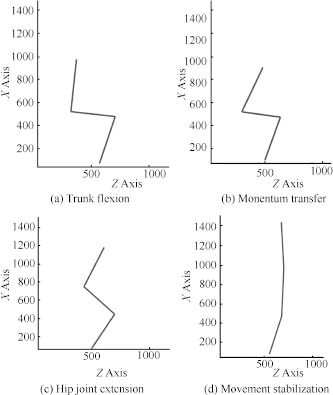
Sit-to-Stand phases
Fig. 8 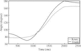
Knee and trunk angular values for sit to stand
-
2)
Verify the performance of the IMUs as compared with the VICON data.
-
3)
Design a adaptive neuro-fuzzy inference systems (AN-FIS) based sensor fusion system by using the output data from VICON and IMUs.


3.2 Simulation of EJAD assisting a patient during stand up
Computer simulation is used to verify the performance of the system. In this simulation, the experimental data were used to obtain the reference angles, displacement and velocities for the EJAD system joints as shown in Fig. 9. The human model (red sticks) stands up like a healthy subject and EJAD assists him during this operation as shown in Fig. 10.

Angles, displacement and velocities of EJAD during sit-to-stand

Subject supported by EJAD during the sit-to-stand
4 Proposed control strategy
The patient with the EJAD performs autonomously important tasks like walking and sit-to-stand without the necessary support of the caregiver. This relaxes the caregivers to reduce the physical efforts in assisting the patient and decreases the risk of back problems. The EJAD helps the patient to use his remaining physical strength and this in turn will help the patient to keep his fitness conditions over time. In the following, the proposed control scheme and the ANFIS sensor fusion algorithm will be described. The ANFIS technique is an algorithm that combines the neural networks and fuzzy logic approaches[20].
To design the interactive control between patient and EJAD, the posture of the user by using inertial sensors will be reconstructed. IMUs are placed at the patient leg and trunk as shown in Fig. 11. The raw data of the inertial sensors are elaborated with an ANFIS algorithm to estimate the patient posture and to generate the reference for the end effector in the world coordinates. The inverse kinematics solution of the EJAD, calculated in the previous section, will be used to determine the joints variables.

General motion control diagram of EJAD
4.1 Proposed control scheme
The proposed control scheme for EJAD mechanism can be divided into two stages as shown in Fig. 12. In the first stage, the initialization of the system and the recognition of the position and coordinates of the patient with respect to the EJAD are carried out. A laser range finder (LRF) is used to measure the horizontal distance between the patient and the system. In the second stage, when the user wants to stand up, the system reads the inertial sensors data to determine the patient posture using the ANFIS algorithm. After knowing the posture of the patient, it is possible to know the required position of the end effector of the EJAD. Using the inverse kinematics solution of the EJAD, the values of joints variables can be calculated. Finally, the controller will use these joints values as references for the motors to move to the required position of end effector while assisting the patient.

Flow chart of the proposed control scheme
4.2 Sensor fusion process
To design the interactive control between the patient and EJAD, IMUs data are used to calculate the posture of the human. The raw measurements of trunk inertial sensor and leg inertial sensor are used as inputs to an ANFIS algorithm to estimate the posture of the patient as shown in Fig. 13. Part of the data from sit-to-stand experiments are used as training data set while the rest are used as testing data set to design the fuzzy sensor fusion. The design procedure of fuzzy sensor fusion is as follows:

Inputs and outputs of ANFIS
Step 1. Collect the training data from the sit-to-stand experiment for healthy subject with VICON and WB-3 systems. Two experimental data sets are used as training data set while the third experimental data set is used for testing.
Step 2. A script in Matlab organizes the acceleration data of the leg and trunk, and the angular speed of the leg as inputs for the ANFIS algorithm. The output data consists of the coordinates obtained by the VICON system data.
Step 3. ANFIS training. The training data is used to train the ANFIS algorithm.
Step 4. Designing the fuzzy sensor fusion. Fig. 14 shows the surfaces of the generated fuzzy sensor fusion system.

Inputs and outputs of ANFIS
Step 5. Test the output of the generated fuzzy sensor fusion system with the data measured by the VICON system.
Two ANFIS-based fusion systems are designed to obtain the XZ position of the end effector. Each ANFIS-based system has three inputs with three triangular type fuzzy membership functions for each input variable.
5 Results
The performance of the proposed control strategy is verified with the data measured from the VICON system for healthy subjects. The data collected using the inertial sensors on the leg and trunk of the subject are used as inputs to the ANFIS-based sensor fusion. Fig. 15 shows the results of the ANFIS-based fusion system. The ANFIS fusion system estimates the path of the end effector. The estimated path is very close to the real path given by the VICON system, with a max error of about 0.04m as shown in Fig. 16. The estimated path of the end effector is then applied to the EJAD inverse kinematics solution to calculate the displacement and the angles of EJAD joints as shown in Fig. 17.

The output XZ-result from ANFIS system

The path of EJAD end effector

The displacement and angles of EJAD
For force transmission analysis, the device will carry 50 % of person weight. The subject weight is 500 N. Therefore, the device will carry 250 N maximum in the vertical direction. Figs. 18 and 19 show the torques of the EJAD.

Torque on second joint

Torque on third joint
6 Conclusions
The analysis and simulation of a new assistive device named EJAD are presented. It is proposed to help elderly people to use their remaining physical strength during sit-to-stand activity. The forward and inverse kinematics solutions are derived. Experiments using VICON and WB-3 systems are carried out to determine the human posture during sit-to-stand activity. An ANFIS-based sensor fusion system is designed to estimate the patient posture from the inertial sensor data. A control scheme is proposed for controlling EJAD actuators and a computer simulation is conducted to evaluate the performance. The results indicate that the generated path for EJAD is close to the real path of healthy subject with a max error of 0.04 m. In future work, an increasing number of IMUs will be used to estimate the human posture to improve the performance of the EJAD.
References
K. Kevin, H. Wan. An Aging World: 2008 International Population Reports, U. S. Department of Health and Human Services and U. S. Department of Commerce, 2009.
D. Chugo, T. Asawa, T. Kitamura, J. Songmin, K. Takase. A moving control of a robotic walker for standing, walking and seating assistance. In Proceedings of the IEEE Inter- national Conference on Robotics and Biomimetics, IEEE, Bangkok, Thailand, pp. 692–697, 2009.
O. Salah, A. Ramadan, S. Sessa, A. A. Abo-Ismail. A systematic approach for design a low-cost mobility assis-tive device for elderly people. In Proceedings of World Academy of Science, Engineering and Technology, Paris, France, pp. 571–576, 2011.
A. Pervez, L. Yo-An, P. Hyeshin, R. Jeha. Active synchronized motion control for comfortable walking support. In Proceedings of International Conference on Control, Automation and Systems, IEEE, Seoul, South Korea, pp. 2714–2718, 2007.
Y. Hirata, J. Higuchi, T. Hatsukari, K. Kosuge. Sit-to-stand assist system by using handrail and electric bed moving up and down. In Proceedings of the 2nd IEEE RAS & EMBS International Conference on Biomedical Robotics and Biomechatronics, IEEE, Scottsdale, AZ, USA, pp. 187–192, 2008.
R. Kamnik, T. Bajd. Robot assistive device for augmentng standing-up capabilities in impaired people. In Proceedings of IEEE/RSJ International Conference on Intelligent Robots and Systems, IEEE, Las Vegas, NV, USA, vol. 4, pp. 3606–3611, 2003.
K. Kong, D. Jeon. Fuzzy control of a new tendon-driven exoskeletal power assistive device. In Proceedings of IEEE/ASME International Conference on Advanced Intelligent Mechatronics, IEEE, Monterey, CA, USA, pp. 146–151, 2005.
O. Salah, A. A. Ramadan, A. A. Abo-Ismail, M. Fujie, A. Takanishi. Development of an assistive device for elderly people: Fuzzy sensor fusion experimental study. In Proceedings of 2012 IEEE International Conference on Robotics and Biomimetics, IEEE, Guangzhou, China, pp. 1212–1217, 2012.
J. Denavit, R. S. Hartenberg. A kinematic notation for lower-pair mechanisms based on matrices. Journal of Applied Mechanics, vol. 22, pp. 215–221, 1955.
K. Yamamoto, M. Ishii, H. Noborisaka, K. Hyodo. Stand alone wearable power assisting suit-sensing and control systems. In Proceedings of the 13th IEEE International Workshop on Robot and Human Interactive Communication, IEEE, Kurashiki, Okayama, Japan, pp. 661–666, 2004.
K. Takahashi, H. Kadone, K, Suzuki. Head orientation sensing by a wearable device for assisted locomotion. In Proceedings of the 2nd Augmented Human International Conference, ACM, New York, USA, 2011.
N. Hata, Y. Hori. Realization of robotic-suit for walking assistance. In Proceedings of the SICE 2004 Annual Conference, IEEE, Sapporo, vol. 3, pp. 2266–2271, 2004.
Z. Lin, M. Zecca, S. Sessa, L. Bartolomeo, H. Ishii, K. Itoh, A Takanishi. Development of an ultra-miniaturized iner-tial measurement unit WB-3 for human body motion tracking. In Proceedings of the 2010 IEEE/SICE International Symposium on System Integration, IEEE, Sendai, Japan pp. 414–419, 2010.
H. Y. Zhou, T. stone, H. S. Hu, N. Harris. Use of multiple wearable inertial sensors in upper limb motion tracking. Medical Engineering and Physics, vol. 30, no. 1, pp. 123–131, 2008.
Y, Q. Tao, H. S. Hu, H. Y. Zhou. Integration of vision and inertial sensors for 3D arm motion tracking in home-based rehabilitation. The International Journal of Robotics Research, vol. 26, no. 6, pp. 607–624, 2007.
H. Y. Zhou, H. S. Hu, Y. Q. Tao. Inertial measurements of upper limb motion. Medical and Biological Engineering and Computing, vol. 44, no. 6, pp. 479–487, 2006.
VICON MX, [Online], Available: http://www.vicon.com, March 24, 2013.
S. Sessa, M. Zecca, Z. H. Lin, L. Bartolomeo, H. Ishii, A. Takanishi. A methodology for the performance evaluation of inertial measurement units. Journal of Intelligent & Robotic Systems, vol. 71, no. 2, pp. 143–157, 2013.
M. Schenkman, R. A. Berger, P. O. Rilley, R. W. Mann, W. A. Hodge. Whole-body movements during rising to standing from sitting. Physical Therapy, vol. 70, no. 10, pp. 638–648, 1990.
J. S. R. Jang. ANFIS: Adaptive-network-based fuzzy inference system. IEEE Transactions on Systems, Man, and Cybernetics, vol. 23, no. 3, pp. 665–685, 1993.
Acknowledgement
The first author acknowledges the Mission Department of the Ministry of Higher Education of Egypt for granting the scholarship to carry out graduate studies in Egypt-Japan University of Science and Technology. We would like also to thank Professor Massimiliano Zecca and all the members of Waseda University for their suggestions, guidance and advice. Finally we would like to give thanks to Kyushu University which offered the first author a short-term travel grant to Japan.
Author information
Authors and Affiliations
Corresponding author
Additional information
This work was supported in part by a scholarship provided by the Mission Department, Ministry of Higher Education of the Government of Egypt.
Omar Salah received his B. Sc. degree in mechatronics section from Mechanical Engineering Department, Faculty of Engineering, Assiut University, Assiut, Egypt, with grade distinction with honor’s degree in 2007. He received his M. Sc. degree in mechatronics and robotics engineering from Innovation Design Engineering School, Egypt-Japan University of Science and Technology (E-JUST), Egypt in 2012. Now he is a Ph. D. candidate in Department of Mechatronics and Robotics, E-JUST, Egypt.
His research interests include rehabilitation, mechatronics system, intelligent control and mobility assistive device.
Ahmed A. Ramadan received his B. Eng. and M. Sc. degrees in computer engineering and automatic control from Electrical Engineering Department, Tanta University, Egypt in 1996 and 2002, respectively. Then he worked toward the Ph. D. degree from late 2005 till 2009 at Systems Innovation Department, Graduate School of Engineering Science, Osaka University, Japan. Starting from 2009, he was an assistant professor at Computers Engineering and Automatic Control Department in Tanta University. At the beginning of 2010, he was granted a research fellowship for two years to work as an assistant professor in Mechatronics and Robotics Engineering Department, E-JUST, Egypt. He is a member of the Institute of Electrical and Electronics Engineers (IEEE).
His research interests include robotics engineering, artificial intelligence techniques and automatic control.
Salvatore Sessa received his M.Sc. and Ph. D. degreess in electronic engineer at the Department of Electric, Electronics and System Engineering, University of Catania, Italy in 2004 and 2008, respectively. He is currently an assistant professor at the Graduate School of Creative Science and Engineering, Waseda University, Tokyo, Japan. He is also associate professor at the Department of Mechatronics and Robotics Engineering, E-JUST, Borg El Arab, Egypt.
His research interests include Micro-Electro-Mechanical-System (MEMS) sensors, sensor fusion algorithms, human motion analysis, and mobile robotic navigation and localization.
Ahmed Abo Ismail received his Ph.D. degree from Tokyo Institute of Technology (TIT), Japan in 1979. He is a full professor of automatic control and mechatronics at E-JUST, Egypt. He is an honorary professor of Budapest Technology, Hungary. He was granted a Fulbright award fellowship as a visiting professor to Pennsylvania State University (PSU), USA in 1987. He is a member of the technical editorial Board of the ACTA polytechnica hungaraica journal of applied sciences, Budapest, Hungary. He is the ex-dean of the faculty of Engineering, Assiut University, Assiut, Egypt. He is currently the E-JUST provost, vice president for education and academic affairs, E-JUST, Egypt.
His research interests include intelligent and robust control, smart grippers design, intelligent mechatronics system, VR- Haptic surgical simulators, surgical robots, and assistive devises design.
Masakatsu Fujie received the M.Sc. degree from the Graduate School of Science and Engineering, Waseda University, Tokyo, Japan in 1971, and the Ph.D. degree in engineering from Waseda University in 1999. From 1971 to 2000, he was with the Mechanical Engineering Research Laboratory, Hitachi Ltd., where he was a senior researcher during 1984 and a principal researcher and project leader for the medical and welfare Apparatus Development Project during 1995. Since 2001, he has been a professor with the Faculty of Science and Engineering, Waseda University, where he is the director of the Global Robot Academia for MEXT Global COE Program. He is now an IEEE Fellow, a JSME Honorary Member, a JSME Fellow, and a RSJ Fellow.
His research interests include surgical robots, image guided surgery, endoscopic surgery, and assistive and rehabilitation robots.
Atsuo Takanishi received the B.Sc., M. Sc. and Ph. D. degrees in mechanical engineering from Waseda University, Japan in 1980, 1982 and 1988, respectively. He is currently a professor at the Department of Modern Mechanical Engineering, Waseda University, and a concurrent professor and director of the Humanoid Robotics Institute (HRI), Waseda University. He is a member of Robotics Society of Japan (a board member in 1992 and 1993), Japanese Society of Biomech-anisms, Japanese Society of Mechanical Engineers, Japanese Society of Instrument and Control Engineers and Society of Mastication Systems (a major board member from 1996 to current), IEEE and other medicine and dentistry related societies in Japan.
His research interests include humanoid robots, such as biped walking humanoid robots, wind instrument player robots, emotion expression humanoid robots, patient simulator hu-manoid robots, ultrasonic diagnosis robots, colonoscopic diagnosis robots, and ultra small inertial motion sensing units.
Rights and permissions
About this article

Cite this article
Salah, O., Ramadan, A.A., Sessa, S. et al. ANFIS-based Sensor Fusion System of Sit- to- stand for Elderly People Assistive Device Protocols. Int. J. Autom. Comput. 10, 405–413 (2013). https://doi.org/10.1007/s11633-013-0737-6
Received:
Revised:
Published:
Issue Date:
DOI: https://doi.org/10.1007/s11633-013-0737-6