
Abstract
The Magnetospheric Multiscale (MMS) mission is the fourth mission of the Solar Terrestrial Probe (STP) program of the National Aeronautics and Space Administration (NASA). The MMS mission was launched on March 12, 2015. The MMS mission consists of four identically instrumented spin-stabilized observatories which are flown in formation to perform the first definitive study of magnetic reconnection in space. The MMS mission was presented with numerous technical challenges, including the simultaneous construction and launch of four identical large spacecraft with 100 instruments total, stringent electromagnetic cleanliness requirements, closed-loop precision maneuvering and pointing of spinning flexible spacecraft, on-board GPS based orbit determination far above the GPS constellation, and a flight dynamics design that enables formation flying with separation distances as small as 10 km. This paper describes the overall mission design and presents an overview of the design, testing, and early on-orbit operation of the spacecraft systems and instrument suite.
1 Introduction
The Magnetospheric Multiscale (MMS) mission is a NASA Solar Terrestrial Probe mission to investigate and understand the fundamental plasma physics phenomenon of magnetic reconnection, the conversion of magnetic energy into particle energy by means of which energy is transferred from the solar wind into Earth’s magnetosphere and then released explosively in the magnetotail (Burch et al. 2015, this issue). MMS accomplishes this investigation by creating an in-situ laboratory of four identical spacecraft flying in formation through Earth’s magnetopause and magnetotail. Figure 1 depicts the four-spacecraft MMS constellation and shows a photograph of one of the completed observatories.

Artist’s conception of the MMS constellation flying in formation (top) and a completed observatory (bottom)
Unlike prior missions that have observed the evidence of magnetic reconnection events while focused on relatively large regions of the magnetosphere, the MMS mission has sufficient spatial and temporal resolution to measure the field and particle characteristics of ongoing reconnection events as they occur.
The MMS mission was defined in detail in 1999 by the Magnetospheric Multiscale Mission Science and Technology Definition Team (Curtis 1999) and identified as the highest priority moderate-size mission in the National Research Council’s 2003 Solar System Exploration Survey (NRC 2003). NASA initiated formulation of the mission in May 2002 and by 2006 had assigned the mission to the Goddard Space Flight Center (GSFC) and selected the Southwest Research Institute (SwRI) to lead the MMS science investigation. The mission was directed to be an in-house mission with GSFC providing project management and systems engineering, mission assurance, the spacecraft, the mission operations infrastructure, and integration and test of the four observatories. SwRI was contracted to lead the science team, design the science investigations, and provide the Principal Investigator, the integrated Instrument Suite, and science data analysis.
This paper describes the design, construction, testing, launch and commissioning of the four MMS Observatories. The design of the mission, and the origin of many of the constraints that drove the Observatory design, are described in detail elsewhere in this issue (Fuselier et al. 2014), in the references (Gramling 2010). In addition a Special Session of the AAS/AIAA Astrodynamics Specialist Conference in 2009 was devoted to MMS mission design and flight dynamics (Carpenter 2009). A concise overview of the mission follows here to provide context for the subsequent sections of this paper.
1.1 Mission Overview
MMS was successfully launched on March 12, 2015, and is currently in its five-and-half-month commissioning phase. Science operations begin in September 2015. The four MMS observatories were launched together from the Cape Canaveral Air Force Station in Florida stacked atop an Atlas-V 421 rocket (Fig. 2). The observatories were initially placed into an elliptical Earth orbit with a \(28.5^{\mathrm{o}}\) inclination and perigee and apogee at 1.08 Earth radii (RE) and \(12 \mathrm{R}_{\mathrm{E}}\), respectively. The observatories were sequentially released from the Centaur upper stage with a spin rate of 3 rpm. The releases were timed to establish the initial constellation separation distances. During the first three weeks, each observatory was maneuvered to raise the perigee to \(1.2 \mathrm{R}_{\mathrm{E}}\), resulting in an orbit with a period of approximately one day. The launch trajectory was specified to place the first apogee at approximately 04:18 in the Geocentric Solar Ecliptic (GSE) reference frame (Fig. 3).

Left: The MMS launch vehicle, a United Launch Alliance Atlas V 421 with a Centaur upper stage, at Launch Complex 41 on the day of the launch. Top right: the stacked MMS observatories in the Vertical Integration Facility shortly before the fairing was closed. Bottom right: illustration showing the order of the stacked of observatories and the dimensions of the stack

MMS orbital geometry and science Regions of Interest (ROI)
The precession of the GSE frame as Earth orbits the Sun will sweep the orbit into the magnetopause and the first science region of interest (ROI) (Fig. 3), which spans 14:00-10:00 GSE time. During the first five and half months (165 days) of the mission while the orbit is precessing toward the ROI, the observatories are commissioned and the constellation is maneuvered into its initial tetrahedral science formation with a separation distance of approximately 160 km. During the next six months the first phase (Phase 1) of the MMS science mission begins as the constellation repeatedly passes through the ROI each orbit. Phase 1 is completed during the second sweep through the magnetopause ROI 12 months later and ends with the initiation of the maneuvers to adjust the orbit for the second phase (Phase 2) of the science mission. The observatories are, on average, maneuvered every two weeks to adjust and maintain the formation and attitude (spin axis orientation) with the formation size potentially being resized to as small as a 10 km separation distance based on the ongoing science results. Orbit determination for MMS is performed primarily on-board using a weak-signal GPS navigation system, as well as the GSFC Navigator system and the Goddard Enhanced Onboard Navigation System (GEONS), both of which are described in a later section of this paper. Communication is performed with an S-Band system which utilizes NASA’s Space and Ground Networks for real-time telemetry and commanding and the Deep Space Network (DSN) for science data downlink as well as telemetry and commanding. The four observatories share one space-to-ground link frequency. The MMS observatories will collect science data continuously, resulting in a volume of data much larger than can be downlinked with the available bandwidth and durations of ground communication passes. To surmount this, an innovative scheme of continuously identifying data segments likely to have captured reconnection events and tagging them for downlink while eventually overwriting data of less importance has been developed by the MMS science team (Fuselier et al. 2014).
Phase 2 of the MMS mission commences as the constellation nears the end of its second sweep through the ROI in the magnetopause and a series of maneuvers is executed to raise the apogee to \(25 \mathrm{R}_{\mathrm{E}}\). The apogee raising maneuvers are performed over about 90 days; when these maneuvers are complete, the tetrahedral formation is reestablished with an initial separation distance of 400 km. During the next 160 days the constellation executes the Phase 2 of the science mission while sweeping through the magnetotail ROI (Fig. 3.) Operations in Phase 2 are very similar to those in Phase 1 but with some significant differences due to the impact of the greater apogee on both communication and navigation (Fuselier et al. 2014; Gramling 2010; Baker et al. 2015).
MMS mission operations are conducted by an integrated but geographically distributed team with the Mission Operations Center (MOC) and Flight Dynamics Operation Area (FDOA) located at GSFC in Maryland, the Science Operations Center (SOC) located at the Laboratory for Atmospheric and Space Physics (LASP) in Colorado, and the Instrument Team Facilities (ITF) located at each of the institutions that built and operate the individual instruments (Baker et al. 2015). The overall architecture of the MMS operations and ground system is shown in Fig. 4.

MMS ground system architecture
The MMS observatories are predicted to have fuel reserves sufficient to enable an extended mission of up to 2 years. The observatories will reenter the Earth’s atmosphere approximately 15 years after launch and completely demise in an uncontrolled reentry.
2 Observatory Architecture
2.1 Key Design Drivers
The definition of the MMS mission requires four spinning observatories flying in a controlled formation to perform the planned scientific measurements. Spinning spacecraft are needed to deploy and maintain the wire booms and provide for continuous full sky coverage from the instrument complement, while a four-observatory formation is required to enable in-situ measurements in three dimensions, with the formation size being chosen to correspond to the scale of magnetic reconnection phenomenon. The design of the individual observatories was driven by a number of key requirements:
-
Magnetic and electrostatic cleanliness: To measure the electromagnetic fields with the required precision, the MMS observatories were designed to have very low levels of electrostatic charge and magnetic moment in the observatories themselves. This requirement influenced the design of all aspects of the observatories. The MMS observatories have a maximum of 4 V of electrostatic charge build up and a residual magnetic dipole moment of less than 1 A/m2 in flight.
-
High accuracy orbit determination: To maintain the required formation, precision navigation is required. MMS achieves this by employing an onboard GPS navigation system, the Navigator system (Sect. 3.5).
-
Closed loop maneuver control: To control and change the formation, propulsive maneuvers must be controlled in a closed loop manner. Closed-loop control is achieved via the use of a highly accurate accelerometer system, the acceleration measurement system (AMS) (Sect. 3.7).
-
Low power avionics: Because the solar arrays must be body mounted on the spinning observatories, and thus of limited size, the avionics were required to consume the lowest possible power.
-
Precise control of mass properties: The spinning observatories must have their spin axis aligned with the body axis within 0.65° in order for the instruments to operate properly.
-
Modular design: To integrate and test four observatories in a time efficient manner, it was necessary to design the observatory such that the instrument suite, the spacecraft bus, and the propulsion module could be built and tested separately and then integrated to form each of the four observatories.
-
High reliability: To achieve full mission success, all four observatories must be operational. To achieve an acceptable level of predicted reliability for the entire constellation, each of the observatories has a fully redundant spacecraft bus and a high level of redundancy in the instrument suite.
2.2 Observatory System Design
Each of the four MMS observatories consists of an octagonal central body and eight deployable structures (Fig. 5). Two of these deployable instruments are the ADP booms, which extend 15 m in each direction along the spin axis of the observatory. The other six appendages lie in the spin plane; they consist of four Spin-Plane Double Probe (SDP) wire booms (each 60 m long) and two rigid magnetometer booms (each 5 m long). The central body consists of 3 major subassemblies or modules: (1) The central thrust-tube structure that houses the four propellant tanks, propulsion components, and the two axial boom instruments, the Axial Double Probes (ADP), which deploy along the \(\pm\mathrm{Z}\) axes. The thrust tube also provides attachment points for the separation systems and carries primary launch loads through the stack of four observatories during launch. (2) The instrument or upper deck carries the majority of science instruments, science electronics, instrument harnesses, one communication antenna, the GPS antennas, and six thrusters. (3) The spacecraft or lower deck carries the majority of spacecraft electronics, spacecraft sensors, spacecraft harness, propulsion fill and drain valves, six thrusters, and one of the two Fly’s Eye Energetic Particle Sensors (FEEPS). Both decks are stiffened via struts and columns that span the gap between the two decks and connect the outer edges to the thrust tube rings. Each deck also has optical solar reflector (OSR) thermal radiators for select components. Each face of the octagon is closed out with a solar panel and except for the OSR radiators the spacecraft and instrument deck the exterior surfaces are covered with multi-layer insulation (MLI). The observatories are nominally identical, with the exception of Observatory #4, which has a lightweight structure in place of an active separation system on top. Each observatory carries 410 kg of monopropellant fuel and has a total mass of either 1354 kg (Observatories #1 through #3) or 1339 kg (Observatory #4) at launch.

Drawing of an MMS observatory showing the FIELDS investigation deployables
The overall construction of the MMS observatories is shown in Fig. 6 with the dimensions shown in Fig. 7. The functional system design of the MMS observatories is illustrated in the system block diagram shown in Fig. 8. In the next section each of the spacecraft subsystems is described followed by a section devoted to the instrument suite.

Exploded view of the MMS spacecraft bus

MMS observatory dimensions and coordinates

MMS observatory architecture
3 Spacecraft Bus
The MMS spacecraft bus design is a block redundant design with cross strapping of redundant elements limited to only the communication subsystem. The spacecraft bus interfaces to the instrument suite through the Central Instrument Data Processor (CIDP), which is also block redundant (Sect. 4.3). Spacecraft bus redundant sides are cross strapped to the redundant CIDP sides. Each spacecraft bus subsystem is described in the following subsections.
3.1 Command & Data Handling (C&DH) Subsystem
The C&DH subsystem (Raphael et al. 2014) provides the spacecraft bus flight computer (used by the onboard FSW). Functions include interfacing to the Instrument Suite through the CIDP and directly controlling and communicating with all spacecraft bus subsystems. The C&DH subsystem consists of one box with two of each card (backplane, low voltage and power services (LVPS) card, communication card, processor card and analog card). One side is designated as Side A or the primary side and the other as Side B or the redundant side. Only one side (primary side) is active (fully powered on) at a given time with exception to the communication card on the B side, which is always powered. The C&DH processor is not needed for minimum-power observatory survival; it is turned off during a power load-shed. The communication cards always remain powered. The C&DH subsystem and its overall relationship to the other observatory subsystems is illustrated in Fig. 9.

MMS C&DH system and interfaces
A key aspect of the MMS architecture is the use of SpaceWire as the primary spacecraft communication bus. The SpaceWire network provides communication paths for commands and telemetry, including science data, for most subsystems in the observatory. The network is a cold spare, redundant configuration with the exception that the topology provides for the cross strapping of the CIDP redundant A and B sides to the C&DH and the internal cross strapping of the redundant communication cards within the C&DH.
The MMS implementation of SpaceWire conforms to the European Cooperation for Space Standardization (ECSS) Space Engineering SpaceWire—Links, Nodes, Routers and Networks (ECSS-E-50-12A) standard. The MMS design also includes enhancements implemented in the GSFC SpaceWire Target Intellectual Property (IP) cores which improve packet error handling and simplify the use of the SpaceWire remote memory access protocol (Raphael et al. 2014; Haddad 2013).
With the exception of the processor card, the backplane and all of the other cards in the C&DH were designed based on current state-of-the-art GSFC circuit designs employed on contemporary Goddard missions. The processor card is a new design for MMS that utilizes a RH-CF5208 radiation-hardened microprocessor based on Motorola’s ColdFire architecture. This processor was chosen because of its low power consumption and flight heritage. The other key elements of the processor card include the Arbiter FPGA which is the central interface/controller on the processor card, the SpaceWire router FPGA which is also used on the communication card, and a variety of memories and voltage regulators. The processor card performs time management and distribution for the Observatory using the precision time signal from the Navigator subsystem described in Sect. 3.5. The processor card also has an internal 40 MHz oscillator which it defaults to if the Navigator signal is not available.
Figure 10 shows a processor card block diagram, and Fig. 11 shows the C&DH box annotated with its key features. Additional details about the design of the MMS C&DH can be found in the references cited above.

MMS processor card block diagram

MMS C&DH box
3.2 Spacecraft Flight Software (FSW)
The FSW executes in the Motorola RH-CF5208 (ColdFire Processor) located on the C&DH processor card. There are two copies of the FSW on each spacecraft (2 per side (A&B)) each residing in separate banks of EEPROM (thus there are 16 total copies of the FSW in flight). The FSW is functionally the same across each spacecraft. There are slight differences (where appropriate) for unique characteristics of each spacecraft (i.e. sensor/actuator alignments, SpaceWire routing, spacecraft ID, etc.) These differences are stored in the MMS FSW in what is known as FSW “tables”.
The MMS spacecraft FSW is comprised of custom designed mission flight software, as well as the GSFC-developed core Flight Executive, and Core Flight Software System software (Wilmot 2006), with modifications made to facilitate the MMS mission. The FSW utilizes the Real Time Executive for Multiprocessor Systems (RTEMS) operating system. It is designed as a pre-emptive multi-tasking system where tasks execute in prioritized fashion.
The FSW is responsible for the management of onboard spacecraft commanding (both real-time and stored), telemetry, onboard fault management, onboard attitude determination and control (including interfacing to the ACS actuators and sensor complement), housekeeping data recorder management, time management and distribution, management of the SpaceWire network, check-summing (to ensure memory integrity) of spacecraft memory (both RAM and EEPROM), memory scrubbing, onboard file management including uplink/downlink of files utilizing the Consultative Committee for Space Data Systems (CCSDS) File Delivery Protocol (CFDP) and analog data acquisition. The FSW is also the primary interface to the Instrument Suite Central Instrument Data Processor (CIDP).
Flight operation of an MMS observatory is primarily accomplished by the execution of absolute time sequences (ATS) which are multi-day files of FSW commands, data table loads, and telemetry filter masks which are uploaded periodically. The ATS are the output product of the flight operations team’s mission planning system. The FSW executes the ATS commands, some of which in turn call relative time sequences (RTS) which are activity specific sequences of commands stored on-board. RTS are also the fundamental building-blocks of the fault detection and correction system which consists of a set of telemetry watch/action points and Boolean logic that calls the appropriate RTS for a given fault situation. Both individual commands and execution of RTS can be directly commanded from the ground when required.
The FSW can be modified (patched) in flight and can be re-written during the mission as needed. A copy of the FSW is maintained on the ground in a high fidelity spacecraft test-bed or FlatSat for validation of critical flight activities prior to execution and to test software changes before they are uploaded. The MMS FSW architecture is shown in Fig. 12 and the control modes are shown in Fig. 16.

MMS Flight software architecture
3.3 Electrical Power Subsystem (EPS)
The EPS collects solar energy, stores it, and distributes it to the other subsystems. An MMS observatory requires an orbit-average power capability of 368 W and a bus voltage range of 30–34 V. The system is a direct energy transfer topology with the main elements being solar arrays, a battery, resistive power shunts, and the power systems electronics (PSE). The system and its elements are shown in Fig. 13 and described in more detail below.

Electrical power system
Energy collection is accomplished via eight solar panels. Each panel consists of solar cells, arranged in strings, bonded to a composite substrate panel. The cells (9 strings of 18 per panel for a total of 162 cells per observatory) are EMCORE’s InGaP/InGaAs/Ge ZTJ triple-junction space-grade solar cells. These cells have an average conversion efficiency of 29.5 % (Fatemi et al. 2013). Electromagnetic cleanliness is a key attribute of the MMS solar arrays and was achieved through an innovative, and cost effective, design with a continuously electrically grounded front surface and a back-side harness design that minimized the magnetic dipole moment (Stern et al. 2013). Each panel is connected to the spacecraft structure via four titanium flexures designed to compensate for the differences in thermal expansion between the composite panels and aluminum spacecraft structure.
A 75 A-h at end-of-life Li-Ion battery provides power to the observatory when the observatory is eclipsed by the earth or moon. The battery was procured from ABSL and is a small cell design with 480 individual 1.5 A-h cells configured in 60 parallel strings of 8 cells in series. The open circuit voltage of the fully charged battery is 33.6 V. Over-pressure and over-voltage protection is incorporated in the individual cells, which provides for a high level of redundancy at the cell-string level. The battery cell stings are oriented in a horseshoe configuration to reduce the DC magnetic field while an external cancellation loop was incorporated into the power harness to cancel the batteries AC magnetic field.
The PSE controls the solar array power generation and battery charging. The PSE also distributes and switches electrical power to all observatory subsystems. It is a fully redundant system with an A and a B side housed in a single enclosure. Within the PSE, control and monitoring are performed by the power monitor card (PMC), which communicates with the observatory over a SpaceWire interface and has its control logic and local fault detection and safing hosted in a FPGA. The PMC can also receive “special commands” via RS-422 from the C&DH processor and communication cards. The PMC is the bus master for the redundant \(\mathrm{I}^{2}\mathrm{C}\) communication bus that the PSE utilizes internally. Solar array control is provided by the solar array module (SAM) which employs both coarse (digitally switched) and fine (linear) shunt control to manage the energy flow from the solar arrays, routing excess power to the shunts when necessary. The SAM also has over voltage protection logic which operates as a back-up mode for controlling the battery charging. SAM A/B side redundancy is provided on a single card in the PSE. Power is distributed to the observatory by 3 output modules (OM) per side employing solid state power converters to provide 39 switched outputs with overcurrent protection. Each OM also provides 2 unstitched services that are fuse protected. In the EPS a diode switch card (DSC) provides cross strapping of 10 services, primarily used for heaters, which enabled a reduction in the total required number of services. The DSC opens the returns of the cross strapped loads ensuring magnetic cleanliness. The PSE system block diagram is shown in Fig. 14.

Power systems electronics (PSE)
3.4 Attitude Control Subsystem (ACS)
The ACS provides attitude determination, pointing control and orbit control of the spin-stabilized observatories. The MMS observatories spin at approximately 3 rpm to maintain the necessary tension in the wire booms and allow other instruments to sweep out a full-view of the sky. During the science mission, each observatory spin axis is oriented to within 2° to 5° of ecliptic normal and maintained to within 0.5°. The ACS provides spin-axis and spin-phase knowledge to better than ±0.1° (\(3\sigma\)) with respect to the Sun line—typically achieving a full inertial attitude solution to within ±60-arcseconds (\(3\sigma\)) while in Science Mode using a gyro-less Multiplicative Extended Kalman Filter (MEKF) design specifically developed for the mission (Thienel et al. 2009). Eight 4 lbf off-radial thrusters and four 1 lbf axial thrusters are used to perform orbit adjustment and formation maintenance maneuvers, spacecraft spin rate control, spacecraft momentum vector precession, and spacecraft nutation maintenance. Precision formation maintenance maneuvers are accomplished with use of an accelerometer system used in a closed loop control of the propulsion system. Other ACS flight hardware consists of the star sensor system and digital sun sensors (DSS). A block diagram of the MMS ACS is shown in Fig. 15.

ACS block diagram
ACS control modes include Check Out, Sun Acquisition, Science, Delta-Velocity (Delta-V) and Delta-Momentum (Delta-H) (Fig. 16). The Check Out mode allows open loop individual thruster firing and is activated during the mission’s early operations to perform thruster phasing tests. The Sun Acquisition mode uses feedback of the DSS Sun elevation error to time thruster pulses capable of precessing the spacecraft attitude to a power-positive and thermally safe orientation. The Science Mode used for nominal science is passively stable and considered to be the subsystem’s safe hold mode as it does not use the propulsion system thrusters, although sensor data is continuously processed for full attitude and rate determination. The Delta-V mode controller is an innovative design capable of tracking an inertially commanded velocity profile with errors less than 1.5° (\(3\sigma\)) directionally and 5 mm/s (\(3\sigma\)) in magnitude for maneuvers less than 0.30 m/s (<1 % otherwise) (Queen and Chai 2015; Queen et al. 2015). This precision of execution is achieved using integrated acceleration samples at a very high-rate (100 KHz) by the on-board Acceleration Measurement System (AMS). Gyrodynamic corrections applied to each velocity sample using the attitude and rate products of the on-board Attitude Determination solution. Before each maneuver re-calibration of the system is handled autonomously by on-board filters that detect and estimate the AMS bias residuals and/or any shifts in the spacecraft principal axis. The on-board system is augmented by ground-estimation knowledge of the spacecraft mass properties and thruster performance. An alternate, open-loop, maneuvering sub-mode is also possible (with reduced performance accuracy) should the AMS data be unavailable (e.g. early commissioning phases). Delta-V mode uses both the axial and radial thrusters and maintains 6 degree-of-freedom of the vehicle while following the ground-commanded, time-varying, inertial velocity and attitude profiles. The Delta-H mode adjusts and maintains the spacecraft’s momentum vector magnitude and inertial direction, and is expected to re-orient the momentum of the (fully-deployed) spacecraft roughly 2.6° every two-weeks in less than forty minutes with an accuracy of 0.2° (to compensate for the apparent seasonal procession of the Sun). Delta-H mode is the primary MMS attitude control mode and controls nutation, spin rate, and momentum slews (large and small) simultaneously. Previous spin-stabilized spacecraft have traditionally used multiple control modes to accomplish a similar results. The non-linear Delta-H controller design was originally formulated for a continuous-actuation system using a globally stable Lyapunov method (Reynolds and Creamer 2001; Shah 2011) and adapted for discrete-thrusting use on MMS (Queen and Chai 2015; Queen et al. 2015). High-fidelity Monte Carlo simulations and early MMS flight performance have shown that it has achieved all of the MMS performance and operational simplicity design goals.

ACS control modes
The accelerometer system procured from ZIN Technologies provides delta-V and acceleration data. It has a resolution of less than 1 μg, a dynamic range of ±25 mg and a short term bias stability of less than 1.0 μg/12 h (\(3\sigma\)). A breadboard system was developed for technology risk mitigation. The accelerometer system is a block redundant system within a single enclosure that contains two sets of three orthogonally mounted flight-proven Honeywell accelerometer sensors. Heat is conducted through the enclosure and radiated from the top surface. A ground test mode can be used in a range of ±1.2 g. The accelerometer system has a RS-422 data interface with a 4 Hz output I/O rate.
The star sensor system, which was procured from the Danish Technical University, provides inertial-to-body attitude quaternion data (Figs. 17 and 18). It has a full performance accuracy of 60 arc-sec transverse, 200 arc-sec boresight (\(3\sigma\)) and degraded performance accuracy of 75 arc-sec transverse, 250 arc-sec boresight (\(3\sigma\)) during occultation periods. The star sensor system has spin rate capability up to 4 rpm. Each flight unit consists of internally redundant electronics within a single enclosure, four CCD-based camera head units, and four baffles. The star sensor system has a RS-422 data interface with a 4 Hz output rate.

Star sensor system double data processing unit (DPU)

Star sensor system camera head unit (CHU)
The DSS procured from Adcole Corporation shown in Fig. 19 provides Sun elevation and Sun pulse data. It has a Sun elevation FOV of −87.5° to +62°, and operates at a spin rate range of 1 to 10 RPM. The DSS has sun elevation angle accuracy within 0.3° (\(3\sigma\)) for Sun elevation angle range of ±60° and within 2° (\(3\sigma\)) for ranges greater than ±60°. Sun elevation angle resolution is less than 0.13° and Sun pulse accuracy is 0.25°, repeatable to within 0.025° (\(3\sigma\)). The DSS has a transistor–transistor logic data interface.

Digital Sun sensor
An attitude ground system was developed for ground estimation of center of mass, inertia tensor, attitude, body rates, sensor alignments, and accelerometer bias estimation. This system is used in the FDOA within the MOC. A Goddard Dynamic Simulator (GDS) was built to provide real time simulation of spacecraft dynamics. The GDS was used during flight software testing and is used by the MOC as a spacecraft simulator for procedure checkout.
3.5 Navigator Subsystem
The Navigator subsystem provides autonomous orbit determination (position, velocity and time) using signals from the NAVSTAR GPS with absolute orbit semi-major axis accuracy of 100 m at observatory spin rates up to 3.2 rpm. The Navigator employs special signal processing algorithms in radiation-hardened hardware that enable fast signal acquisition capabilities and improved sensitivity (Bamford et al. 2009; Winternitz et al. 2009). For the MMS mission, the Navigator operates both below and above the GPS constellation. A single Navigator enclosure houses both the primary and redundant Navigator main electronics. Primary and redundant ultra-stable oscillators (USOs) are mounted external to the Navigator chassis. Eight GPS receive only antennas are evenly spaced around the perimeter of the observatory and orthogonal to its spin axis. Front end electronics assemblies (FEAs) are located within one foot of each antenna on the deck struts. To accommodate spinning observatories, an innovative antenna algorithm is used to hand off the signal from one antenna to the next during acquisition and tracking of both strong and weak signals. A GEONS algorithm is used to propagate position, velocity and time during extended periods of GPS signal outages with input from the USO. The Navigator system provides International Atomic Time (TAI) to an accuracy of 325 microseconds during Phase 1 and the same accuracy during Phase 2 for at least 99 out of 100 orbits. A block diagram of the MMS Navigator system is shown in Fig. 20.

Navigator system block diagram
The Navigator box consists of both a primary and redundant Navigator signal processor (SP) card and Navigator-RF card located in a GPS module separated by an EMI shield from a power converter card. Baseband RF is sampled by four analog-to-digital converters (ADCs) and signals are processed by FPGAs and software. The Navigator box provides a 1 pulse per second truth tone and 2 MHz reference frequency to the C&DH via SpaceWire and receives power mode discrete commands via RS-422 from the C&DH. The PSE provides a 28 VDC unregulated bus to Navigator. The Navigator power modes are (1) active, (2) RF off, (3) ultra-low (shuts off all secondary power to the Navigator except to the USO), and off. Special radiation considerations for RF and GPS were incorporated into the design of the box.
The Navigator flight software consists principally of the core GPS software (CGS), GEONS, real-time operating system, and the Nucleus software floating point math library. The CGS provides a number of functions including searching for, acquiring, and tracking RF signals from GPS satellites. It measures the relative delay of the RF signals and extracts data transmitted in RF Signals. The CGS calculates point solutions every 5 s when data is available and adjusts the truth tone (1 pps clock) to align with TAI. Finally, the CGS provides command and telemetry links and collects board health data.
GEONS is government off-the-shelf software developed and supported by GSFC. GEONS contains models for forces that affect the orbit including gravity of nearby bodies, solar radiation pressure, and atmospheric drag. It applies an extended Kalman filter to propagate solutions during periods of limited or no GPS observability. It also models the error mechanism in the USO to produce better truth tone time knowledge during loss of GPS signals.
The USO procured from Frequency Electronics Inc. utilizes a quartz crystal oscillator operating at 5 MHz with very low drift (217 μs in 65 h). It has a radiation-hardened design and is provided power by dedicated 12 V DC/DC converter in the Navigator box. To minimize temperature variations that affect performance, the oscillator is maintained in a dual oven temperature controlled environment.
The FEAs procured from Delta Microwave are fed by the GPS antennas. They provide initial filtering and a minimum of 40 dB of gain amplification. The FEAs are powered via the RF cable from the Navigator box.
The GPS antennas are an in-house GSFC design (Fig. 21); they receive the GPS signals and feed the FEAs. Four antennas located on alternating apexes of each an observatory feed the primary Navigator side, and an additional four redundant antennas located on the open apexes provide block redundancy. The antennas provide a hemispherical pattern and operate in a frequency range of 1574.32 to 1576.52 MHz. The antennas have all aluminum construction at DC chassis ground potential.

MMS GPS antenna
A formation flying test bed provided a high-fidelity simulation and test environment, including hardware-in-the-loop, especially for GPS receiver testing. A cesium frequency standard supplied 10 MHz and 1 pps to synchronize the simulation environment. Two Spirent GPS signal simulator racks generated 8 RF signals to run up to 2 spinning spacecraft simultaneously. Multiple portable Spirent playback simulators were utilized, and rooftop antennas allowed access to authentic GPS signals. Universal counters were used to analyze PPS errors.
Shortly after the GPS receivers were powered on Navigator set several records for the use of GPS in space as the MMS spacecraft flew through their highly elliptical orbit:
-
At the highest point of the MMS orbit, Navigator set a record for the highest-ever reception of GPS signals in space, at more than 70,000 kilometers above the surface of the earth.
-
At the highest point of the MMS orbit, Navigator set a record for the highest-ever GPS solutions, at more than 70,000 kilometers above the surface of the earth.
-
At the lowest point of the MMS orbit, Navigator set a record as the fastest operational GPS receiver in space, at velocities over 10 km/s (22,000 miles per hour)
Previous missions in highly elliptical orbits that flew GPS receivers did so for experimental use only. The GPS constellation is designed to radiate signals downwards, towards Earth’s surface. Using GPS above the constellation, in highly elliptical orbits, requires a specialized GPS receiver with technology allowing it to quickly acquire and receive much weaker signals that are radiated past the limb of the earth by the GPS satellites.
3.6 Communication Subsystem
The MMS communication subsystem provides the data and command link between the observatories and all three of NASA’s networks; the DSN, the Space Network-Tracking and Data Relay Satellite System (SN-TDRSS), and the Near Earth Network (NEN) system of ground stations. Each Observatory has a redundant pair of L3-Cincinnati Electronics transponders operating at 2281.90 MHz and 2101.25 MHz for telemetry/data downlink and command uplink respectively. The transponders each have a minimum output power of 8 W. The transponders communicate with the C&DH communication card via a RS-422 serial interface. The transponders are connected, via diplexers and radio frequency (RF) switch, to a pair of fixed antennas with a toroidal gain pattern. The antennas were specifically designed to provide uninterrupted communication while the observatory is spinning. Both receivers are always powered and the transponder-antenna pair with the best link, based on ground analysis, is selected and turned on by the on-board ATS for downlink during a communication pass. The RF switch is only used in the event of a failure.
All transponders on all four observatories have the same transmit and receive frequencies although each observatory has a unique spacecraft ID (SCID) which associates command and telemetry packets with a specific observatory. During communication passes, observatories are communicated with one at a time, a design decision that simplifies integrated flight operation of four observatories.
The communication subsystem functional diagram is shown in Fig. 22 and the antenna locations and the major components are shown in Fig. 23.

MMS communication subsystem

MMS communication subsystem elements
3.7 Propulsion Subsystem
Each MMS observatory utilizes a monopropellant hydrazine blow-down propulsion system to accomplish maneuvers. The propulsion system features eight 4-lbf (18-N) radial thrusters and four 1-lbf (4.5-N) axial thrusters. The radial thrusters are utilized for spin-rate control, attitude control and delta-V maneuvers. The axial thrusters are used for nutation and attitude control, momentum change maneuvers, and providing thrust on a plane perpendicular to the plane of the observatory. The thrusters can be operated independently and simultaneously to perform attitude and orbit maneuvers, adjust and maintain formation of the observatories, and accomplish the requisite large apogee-raising maneuvers. Figure 24 shows a schematic of the propulsion system.

Propulsion system schematic
The propulsion system was integrated with the thrust tube before delivery to MMS observatory I&T. Tanks were mounted on four struts to the thrust tube rings, and most of the tank loads are carried through a spherical bearing at the tank outlet boss. Filters, latch valves and pressure transducers were mounted to a component sub-assembly (CSA) and thermally isolated. The fill & drain valves were mounted to a panel on the spacecraft deck and thermally isolated from the panel. Proof tests were performed on the CSA and thruster manifold as well as at the propulsion system level. Figure 25 shows the propulsion system layout within the thrust tube.

Propulsion system/thrust tube layout
Each observatory has a mission propellant load of 410 kg distributed equally among four identical propellant tanks. The propellant tanks have positive expulsion via elastomeric diaphragms and were procured from ATK Commerce. In order to keep the Z location of the observatory center of mass roughly constant throughout the mission, two propellant tanks have their propellant “down” (in the –Z direction) and the opposing tanks have their propellant “up” (in the +Z direction). The tanks are all titanium, cylindrical diaphragm tanks with tab and boss mounts. Figure 26 shows the installation of a propellant tank into the thrust tube/propulsion assembly.

Propellant tank installation
Fill and drain valves, procured from MOOG, were located at the edge of the observatory to allow access for fueling the system with hydrazine and pressurizing the system with Helium. The valves feature a triple seal design with a primary metal-to-metal seat. Figure 27 shows the MMS fill and drain valve assembly prior to integration.

Fill and drain valve assembly
Four latching isolation valves with redundant coils, procured from VACCO Industries, allow preferential draining from any combination of tanks, thus providing center of mass control of the observatory if needed. Each tank has two pressure transducers, procured from Tavis Inc., to measure pressure. The quantity of propellant remaining can be calculated from “book-keeping” each maneuver and thruster valves on time, and from a pressure, volume, temperature (PVT) calculation performed on the ground using telemetry.
The twelve thrusters are arranged to perform axial burns, radial burns, spin-up, spin-down, or various combinations. Since the observatory is spinning, radial maneuvers require the thrusters to be fired along a small fraction of the arc for best propellant efficiency. Each maneuver is analyzed and planned by ground operators for optimum firing arc usage. If the maneuver magnitude is critical, the accelerometer measuring system (AMS) is used in the closed-loop delta-V controller to actively adjust the firing arc and number of thruster pulses to arrive at the exact amount of desired delta-V.
The observatory has a center of gravity offset of 6.6 cm from the geometric center along the observatory’s \(+\mathrm{Z}\) axis. Pulse width modulation (PWM) control of the thrusters is required to allow the thrust centroid to be moved such that it is applied (on a time average basis) through the center of mass of the observatory. During a delta-V maneuver, PWM control allows the attitude of the observatory to be stabilized. Upper spacecraft deck radial thrusters are pulsed at approximately 92 % of the 8 Hz duty cycle, whereas the bottom radial thrusters are pulsed at approximately 62 % of the 8 Hz duty cycle.
Axial thrusters were procured from AMPAC-ISP (Fig. 28), and radial thrusters were procured from Aerojet (Fig. 29). Delta qualification testing was required to validate that the Aerojet MR-106N thruster was qualified for use on the MMS mission (Mulkey et al. 2011). Two flight configuration thruster assemblies were tested in sequential test programs. Mission hot-fire life was tested without PWM and with PWM at a 62 % duty cycle, bounding the upper and lower deck MMS observatory operational requirements.

MMS axial thruster

MMS radial thruster
To avoid freezing the hydrazine fuel, every “wetted” part of the propulsion system is covered with heaters. All valves, tanks, and propellant lines are heated with thermostatically controlled or computer controlled heaters and insulated with MLI. Computer-controlled heaters are used for primary heater services in order to keep the propellant tanks within a few degrees of each other. Precise temperature control is needed to preclude propellant migration from one tank to the next.
A wet mass vibration test was performed on Observatory #1 to excite the correct strut to thrust tube modes with the propellant mass simulated in the propellant tanks. Water was loaded into the tanks as a mass simulator because it has a similar mass density to hydrazine. After the test, bulk water was expelled from the tanks, and multiple vacuum and hot gas cycles were used to dry the tanks to a certified level.
A center of mass measurement system was developed to measure the propellant center of mass during fueling operations at the launch site. The system consisted of a MMS Observatory transport dolly equipped with high accuracy load cells. All propellant tanks contain internal slosh-reduction diaphragms; the nature of the diaphragms is such that they take on a characteristic shape according to the propellant loading direction and stiffness variations within the diaphragm. The diaphragm’s shape and the location of the propellant’s center of mass are unknown for any given tank. A measure of the location of the propellant’s center of mass was made so that sufficiently accurate knowledge of the observatories’ centers of mass could be provided to the attitude control system and the launch provider.
Two engine valve driver (EVD) cards (primary and redundant) reside in the PSE and EVD System (PSEES) box. The PSEES box is a combination of the PSE and the EVD bolted together as a single chassis. Each EVD card receives commands from the C&DH system and can actuate the deployment of the magnetometer booms, thrusters and latch valves. The latch valve circuits can open or close each of the four latch valves in the propulsion system, and the thruster actuation circuits can fire the twelve thrusters in the propulsion system. Various combinations of thrusters may be fired in steady-state or in a pulsed mode, depending on the desired momentum change or velocity change that is commanded.
3.8 Mechanical Subsystems
The MMS mechanical subsystems are the observatory structure, the separation systems, and the deployable rigid magnetometer booms. The other instrument booms (the ADP and SDP) are provided as part of the Instrument Suite and are discussed in that section.
The MMS structure, which can be seen in many of the previous figures, is an aluminum bolted and riveted design. The octagonal spacecraft and instrument decks, the solar array substrates, and the thrust tube inner bulkheads are constructed using aluminum face sheet/aluminum core honeycomb. The thrust tube, struts, and secondary structural elements are all machined parts. A flight primary structure is shown in Fig. 30. The majority of the electronics assemblies and instruments are hard-mounted to the decks. The exceptions to this are the star sensors, the acceleration measurement system, and the solar array panels, each of which has an interface designed to provide decoupling from thermally induces structural deformations, and for the acceleration measurement system, also provide vibration isolation. The four propulsion tanks are mounted inside the thrust tube with a kinematically determinant system of struts and bearings to decouple thermal and pressure induced tank deformations from the primary structure.

MMS primary structure, shown with mass models of electronics and instruments prior to a test without solar arrays
Although conventional in construction the MMS structural design embodies key challenging attributes that were essential to the overall mission design and development. These are summarized below:
-
The MMS structure is designed to support the launch loads resulting from stacking the four observatories.
-
The design is fully modular in order to support the parallel integration, in separate facilities, of the Instrument Suite on the instrument deck, the spacecraft bus systems on the spacecraft deck, and the propulsion system into and around the thrust tube.
-
The design provides for controlling the center-of-mass location and spin balancing the observatory with a high degree of precision.
-
The design utilizes materials and processes than ensure a very small residual magnetic dipole moment and preclude significant build-up of static electrical charge during flight.
The separation system consists of four 1676-mm-diameter tensioned clamp-band mechanisms each with 8 separation pusher springs. These were procured from RUAG Space in Sweden and are identical to the systems routinely used on Atlas missions. One of these is provided by the Atlas launch vehicle between MMS Observatory #1 and the Centaur upper stage, while the other three are provided and installed by the MMS Project. The separation systems are operated by timers on the Centaur with observatory separations occurring 5 min apart at the specified orbital location.
Each observatory has two 5-m magnetometer booms which carry the three magnetometers (Fig. 31). These are graphite composite rigid booms which are folded on the outside of the spacecraft deck for launch. They are released by Frangibolt Nitinol actuators procured from TiNi Aerospace. The Frangibolts are activated by resistance heaters which in turn stretch and break a titanium fastener. The boom is then deployed by constant force torsion springs at the joints. These mechanism designs are based on numerous successful GSFC mission designs while the composite booms themselves were designed and fabricated at GSFC specifically for MMS.

MMS magnetometer boom
3.9 Thermal Control Subsystem (TCS)
The MMS TCS is a conventional design using temperature sensors, thermostatically and computer controlled heaters, thermal control surfaces, coatings, and MLI to maintain all observatory components within their operational and survival temperatures. The key challenge the MMS thermal control system design team faced was designing a power efficient thermal control system that was simple in order to minimize costs, required the minimal amount of electrical power as solar array size was limited by the requirement for fixed arrays and the launch vehicle fairing size while maintaining observatory thermal control within requirements through solar eclipse durations in excess of four hours during the mission (Zara 2011).
On an MMS observatory active thermal control consists of primary (operational) and secondary (redundant/survival) heaters. These heaters can be actuated from the A-side or B-side from diode switch cards (DSC’s) that cross-strap the heater power supplies in the PSE. Most heaters are controlled with mechanical thermostats but the AMS, the propulsion tanks, and the FPI instruments are computer controlled by the FSW for finer temperature control. These computer controlled set points can be adjusted via ground command.
Passive thermal control employed MLI blankets that cover the majority of external spacecraft surfaces except for OSR radiators and instrument apertures. All blankets are constructed with germanium-coated black Kapton outer layers and have two ground wires to ensure that the MLI is at the same voltage potential as the spacecraft structure. Surfaces that are not insulated with MLI include various coatings with selective infrared emissivity and solar absorptivity for passive thermal control, radiators constructed using OSRs for heat rejection on high power components even while exposed to the Sun, and gold plating on exposed areas of the structure. An example of gold plating is the spacecraft separation system rings which by necessity cannot be covered with MLI. Their gold plating allows them to gain energy while in sunlight and the conductively coupled thermal mass of the gold plated elements is then used to keep the rest of the spacecraft warm when the observatory goes into a solar eclipse—thus saving heater power and allowing the battery to discharge less.
Operationally the MMS thermal design includes pre-conditioning heaters to support planned preheat operations before the observatories enter an extended solar eclipse.
4 Instrument Suite
The four MMS Instrument Suites are identical. Each suite consists of four separate investigations to make in-situ particle and electric and magnetic field measurements in and around regions of magnetic reconnection (Burch et al. 2015). Each suite also includes a pair of support instruments identified as Active Spacecraft Potential Control (ASPOC), which ensure quality plasma measurements by maintaining an electrically neutral spacecraft (Torkar et al. 2014). The investigations include the Fast Plasma Instrument (FPI) (Pollack et al. 2015), the FIELDS investigation (Torbert et al. 2014), the Hot Plasma Composition Analyzer (HPCA) (Young et al. 2014), and the Energetic Particle Detector (EPD) investigation (Mauk et al. 2014). In general, each investigation maintains its own internal state and control algorithms and communicates directly with the Central Instrument Data Processor (CIDP), which controls the Instrument Suite as a whole (Klar et al. 2013). Table 1 lists the investigations, instruments, components, and institutions responsible for their development.
FPI provides in-situ measurements of ions using the Dual Ion Spectrometer (DIS) and electrons using the Dual Electron Spectrometer (DES) above and below the rotational plane of the spacecraft (Pollack et al. 2015). FPI’s instrument data processing unit (IDPU) distributes power to the spectrometers, collects individual instrument data, combines the data to provide a complete map of the plasma environment, and manages the data flow through various compression schemes. The IDPU provides the only functional interface between the CIDP and FPI.
The FIELDS investigation uses analog flux gate (AFG) and digital flux gate (DFG) magnetometers, a search coil magnetometer (SCM), an electron drift instrument (EDI) pair, and electric field double probes in the axial direction (ADP) and spin plane (SDP) to collect information on the local three dimensional electromagnetic field characteristics (Torbert et al. 2014). The FIELDS Central Electronics Box (CEB) receives primary power from the CIDP and distributes secondary voltages, provides data interfaces to the individual instruments and provides a Digital Signal Processor (DSP) to combine data from various sources into a coherent data set that provides processed information on the electromagnetic wave environments. The CEB provides the FIELDS power, command and control interfaces with the CIDP with the exception that the CIDP provides primary power directly to the SDP and ADP deployables and the EDI/GDU components.
The HPCA is a mass ion spectrometer with a unique RF source that is designed to allow measurement of low count ion species in the presence of high-count ion species without decreasing data quality (Young et al. 2014). It is a single unit that includes low voltage and stepping high voltage power supplies, detector electronics, and data processing. All of its power and command/control interfaces are to the CIDP.
The EPD investigation consists of an Electron Ion Spectrometer (EIS) and two each Fly’s Eye Energetic Particle Sensors (FEEPS), which are low power, solid-state detector based instruments that have their data collection and processing operation managed by the CIDP (Mauk et al. 2014). Because of the pre-existing design of EIS, the EPD is the one investigation for which the instruments have their power and data interfaces directly with the CIDP; the CIDP communicates with EIS and the two FEEPS using three control/power interfaces.
4.1 Mechanical
Most of the instrument components are mounted directly to the Instrument Suite deck utilizing an electrically and thermally conductive interface from the component to the deck. During the detailed design phase, instrument placement on the deck was optimized to minimize FOV) obstruction. For example, the HPCA “blind spot” was placed such that its FOV straddled the mag boom. Following this exercise, the science teams reviewed the minimal obstructions and agreed that there was little to no science impact. GSFC designed and procured the decks and delivered them to SwRI for instrument integration and test. Figure 32 shows the instrument components mounted on the inboard side of the Instrument Suite deck when integrated as an observatory. It should be noted that one FEEPS, designated top and another FEEPS, designated bottom, are mounted on the outboard side of the Instrument Suite and spacecraft decks respectively. The SCM preamp is mounted on the inboard spacecraft deck close to the harness that is routed to the magnetometer booms. The AFG and SCM magnetometers are mounted on one 5-m deployable boom and the DFG is mounted on the other boom, both developed by GSFC. The ADP receiving element is mounted on top of each of two self-deployed 12-m coilable booms that are mounted inside the thrust tube and are manufactured to ensure electrostatic cleanliness. Table 2 presents the technical resources for each of the Instrument Suite components.

Instrument suite deck component locations
In addition to the flight electrical harnesses, three additional components are mounted on the Instrument Suite deck that are not part of the main complement of science instruments and electronics boxes. The flight purge manifold (FPM), a sealed cavity with 1 inlet port and 16 outlet ports, distributes regulated and filtered gaseous nitrogen to maintain cleanliness for the 16 science instruments that require purge from delivery through launch. In the final flight configuration, the FPM is connected to the spacecraft T-0 panel that will receive purge gas from the launch vehicle up till launch. The test panel-heater power distribution box (TP-HPDB) and safe/arm (S/A) panel are also mounted on the Instrument Suite deck.
4.2 Electrical
The electrical configuration of the Instrument Suite is illustrated in Fig. 33. This configuration was chosen to simplify inter-instrument and IS to S/C interfaces to a point that complete testing could be conducted at the component and/or Instrument Suite level prior to Observatory I&T. This minimized the amount of essential “first time” testing at the spacecraft level. The simplification of power and command/telemetry interfaces, as well as distribution of data concentration circuitry at the Instrument Suite and investigation level, allowed the various investigations (as well as the Instrument Suite) to be integrated without needing significant amounts of support hardware. This resulted not only in a simplified test program, but also test equipment simplification. Each investigation was provided with one or more essentially identical CIDP-to-instrument interface emulators, and each investigation was emulated by an instrument-to-CIDP test set which reproduced the communication interface of the emulated instrument and provided a minimal set of synthetic data at nominal volumes. The same approach was followed with the spacecraft to CIDP interfaces, with the CIDP team providing GSFC with several CIDP-to-spacecraft emulators and the GSFC providing the CIDP with a spacecraft-to-CIDP interface emulator (S2C). These emulators were installed in Ground Support Equipment Operating System (GSEOS) based computers. The simplification of interfaces also allowed interface verification to be accomplished prior to complete instrument development, reducing integration risk.

Instrument suite electrical interfaces
A total of 26 harness segments make up the Instrument Suite harness that provides the power and signal interfaces between Instrument Suite components. These include the asynchronous and synchronous serial interfaces and CIDP monitored thermistors. The harness also includes spacecraft controlled operational, survival and pre-conditioning heaters, and spacecraft monitored thermistors. SwRI and GSFC engineers worked together to develop a set of specifications to govern the build of the harnesses to meet mission EMI/EMC requirements. A deck and thrust tube mock-up with instrument connector plates were built to help facilitate placement and routing of the electrical harness internal and external to the Instrument Suite deck and to determine the locations of all of the mounting hardware. SwRI built an engineering model set of harnesses to verify design and routing prior to the build of the four sets of flight harnesses.
The MMS spacecraft provides battery sourced primary power for the CIDP, the Instrument Suite operational and actuator functions, and the thermostatically controlled operational and survival heaters. Switched Instrument Suite and actuator power is passed to the various investigations through the CIDP; the heater power for thermostatically controlled survival and operational temperature control is passed to the Instrument Suite heaters through a separate fuse board contained within the TP-HPDB. The MMS spacecraft sends commands, receives engineering and science telemetry, and provides mission timing and synchronization information exclusively through the CIDP. This communication is implemented using the SpaceWire protocol implemented in GSFC-designed FPGA core. The SpaceWire, CIDP power, Instrument Suite power, and actuator power are provided on redundant services. Passing all operational interfaces and the instrument/actuator control powers through the CIDP allows the CIDP level testing to verify most of the interfaces with the spacecraft without depending on availability of the instruments.
Early in the program, the system engineering team developed detailed electrical interface control documents (ICDs) that controlled all aspects of CIDP to instrument interfaces. The CIDP provides instrument power, time synchronization signals, instrument commands, and telemetry ingest functionality to the FIELDS-CEB, FPI-IDPU, HPCA, ASPOC (\(\times2\)), EPD-EIS, and EPD-FEEPS (x2); it provides instrument power to the EDI GDUs DC/DC converter (with GDU data returned through the CEB), deployment power to the SDP motor and door high-output paraffin (HOP) actuator, power to the ADP HOP and Frangibolt® deployable interfaces, and ADP canister heater power. The CIDP communicates with the CEB, IDPU, HPCA, and ASPOC through a synchronous serial LVDS interface, and uses an asynchronous serial LVDS interface for EIS and FEEPS. In addition, the CIDP provides the operational control for FEEPS and necessary command expansion functionality for FEEPS as well as FPI. The CIDP synchronizes all investigations using an encoded LVDS pulse stream indicating Sun pulse timing, 1 pps (time at the tone) indication, and a spin sector (spin rate/5180) indicator referred to as a Delphi pulse. The synchronization interface is implemented in hardware in order to meet the CIDP 50 μs delay requirement derived from the 1 ms timing knowledge requirement across the MMS constellation. Testing the large number of interfaces between the CIDP and the instruments was made simpler by the fact that the types of interfaces are simply four: primary power, asynchronous serial LVDS, synchronous serial LVDS, and LVDS synchronization.
The CEB and IDPU provide further power and command distribution. The CEB provides secondary referenced power to the internal DFG/AFG, EDI interface, and Digital Signal Processing (DSP) boards, and the external SCM Preamp, SDP boom electronics boards (BEB), and ADP electronics boards. The EDI-GDU instruments receive power directly from the CIDP. The CEB provides an LVDS serial interface to the EDI-GDU (through the EDI controller board), the SDP BEBs, and the internal DSP boards. The IDPU provides an LVDS command and telemetry interface and switched primary power to the DES and DIS instruments (4 each). Detailed timing and control for the FIELDS and FPI are provided by the CEB and IDPU respectively. The concentration of interfaces within the CEB and IDPU enable complete investigation testing without the need for a CIDP.
The TP-HPDB is an integrated assembly located near the edge of Bay 1 of the Instrument Suite deck that distributes spacecraft controlled electrical power to instrument and Instrument Suite deck heaters. In addition, the TP-HPDB provided test connector panel interfaces for ground testing the ADP deployment signals, and for the commercially developed, ground use only, 1-wire thermal sensor interface that provided detailed temperature readings during thermal vacuum testing. The original Instrument Suite design routed two services for heaters through the fuse board inside the TP-HBD. Various discoveries relating to thermal damage mechanisms for the HV-801 optocouplers used in the DES, DIS, and HPCA stepping power supply required a modification of the design to allow the spacecraft C&DH software to control the HPCA, DES, and DIS heaters to maintain reduced temperature ranges.
The MMS instruments are capable of operating at their “high voltage safe” levels during ground-based test operations. This state is controlled via a “safe” connector on the Instrument Suite deck with hardware or hardware/software interlocks located in each of the instruments. The S/A panel provides the high voltage and deployable safing and arming circuits for maintaining the safety of the Instrument Suite components during ground testing. Various connector plugs were fabricated to configure the Instrument Suite during ground testing in ambient and vacuum environment. The panel is configured with flight plugs prior to fairing encapsulation at Astrotech during launch processing. This panel also includes deployment safe connectors for the ADP and SDP deployments.
4.3 Central Instrument Data Processor Architecture
The CIDP provides the operational interface between the spacecraft and the Instrument Suite (Klar et al. 2013). It consists of a fully standby redundant set of three boards, the power analog board (PAB), the digital board (DB), and the mass memory module (MMM) as shown in Fig. 34. (Figure 33 shows the power and actuator redundancy configuration.) A compact peripheral component interconnect (cPCI) backplane board ties these three boards together. The CIDP circuit boards implement all of the functions required to:
-
Switch primary power to and provide overcurrent protection for the investigations
-
Collect analog temperature and primary current telemetry
-
Maintain communication and synchronization with the spacecraft
-
Forward commands and collect telemetry to/from the investigations
-
Store, and make available for retrieval, science survey and burst data by time of acquisition and calculate data quality indicators
-
Provide fault detection and containment for the CIDP and the IS (fault correction is primarily the function of the ground control system)

CIDP block diagram
4.3.1 Power Analog Board (PAB)
The PAB receives primary referenced power for three purposes, CIDP operation, Instrument Suite operation, and actuator operation. The CIDP and Instrument Suite power inputs are redundant and are diode OR’ed prior to providing a single derived power line. The actuator power input is single-string. The OR’ed CIDP power input is connected to a DC/DC converter which generates secondary referenced operational voltages. The OR’ed Instrument Suite power input is provided to a series of switches which are controlled within the CIDP. These switches are powered on and off to control the state of the Instrument Suite. In addition to the switch, each of these instrument/investigation switch circuits includes a current sense capability and an over-current protection capability. The actuator power input is treated identically to the Instrument Suite power input with the exception that there is no diode “OR-ing”, as there is only one input line and the switches may be implemented with different FET circuitry. The actuator power switching function is further controlled by external enable signals.
In addition to providing power conversion and switching, the PAB provides a series of thermistor linearization and conditioning circuitry as well as the analog to digital converters that measure the Instrument Suite switch currents and the actuator switch currents.
4.3.2 Digital Board (DB)
The DB consists of a AT697E SPARC V8 embedded processor, with associated support RAM, EEPROM, and PROM, that allows software to control the CIDP functionality. It includes two FPGAs, one that manages the SpaceWire interface and one that manages the instrument interfaces. The SpaceWire control logic includes GSFC developed SpaceWire core IP as well as SwRI developed VHDL to implement the unique specification. Memory is provided to support SpaceWire message buffering. The DB’s instrument interface control logic controls the instrument serial interface (as described in Sect. 4.2) and the timing synchronization interface, and provides message management buffer resources. The processor controls transfer from the input buffers across the backplane cPCI bus into mass memory and from mass memory across the cPCI backplane into the SpaceWire output buffers.
4.3.3 Mass Memory Module (MMM)
The CIDP MMM contains 96 Gbytes of flash memory divided into 24,576, 4 Mbyte files. This amount of memory provides significant margin over the required single orbit data collection for both Phase 1 and Phase 2 of the mission. The additional memory will be used to meet the telemetry data collection requirement during Phase 2b of the mission. In addition to the flash memory, the MMM contains a control FPGA and an EEPROM file block status store (with SRAM shadow). Flash memory radiation testing indicated that the most likely radiation induced errors are likely to cause full block failures to write or erase. With this as a consideration, each 32-bit word of memory is implemented by 6 bytes. Four of the bytes contain the science data. One of the bytes contains a SECDEC hamming code to allow single bit error correction and dual bit error detection for the 32 bits of data. In addition, a sixth byte can be programmed to replace any single byte lost due to flash aging effects or radiation effects. Fast read/write to flash (2 Mbyte/s read and 1 Mbyte/s write) is supported by large write buffers and a full speed cPCI data bus.
4.3.4 CIDP Flight Software
The architecture of the CIDP flight software is illustrated in Fig. 35. The design of the software is modular and layered. The software consists of two layers: the system layer and the application layer. The system layer provides a set of functional application programming interfaces (APIs) that abstract the details of the hardware interfaces. The application layer organizes the required functionality into a series of operating system tasks.

Flight software architecture
The tasks of the CIDP FSW are as follows:
-
The Telemetry Receive Task receives telemetry packets from the Instrument Suite, validates them, and distributes them to other application tasks via a telemetry software bus. Telemetry packets (which are defined in the CIDP to instrument ICDs) received from the Instrument Suite are read from the on-board instrument interface FPGA and can be steered to different FPGA FIFOs by selecting a steering table for the configuration desired (e.g., Fast Survey, Slow Survey, Commissioning).
-
The CFDP Task is responsible for transferring Instrument Suite data to and from the MMM. The task also cycles the GSFC-supplied CFDP engine and handles handshaking with the CFDP engine at the MMS MOC.
-
The Command Receive Task receives command packets from the spacecraft, validates them, and distributes them to the other applications via the command bus for internal processing or forwarding to an instrument.
-
The Relative Time Sequencer (RTS) Task was a late addition to the software design to accommodate command shortcomings in the FEEPS and FPI instruments. It runs macros that send commands to the FEEPS and FPI instruments. Macros are uplinked from the ground, and consist of a set of commands necessary for the instrument to enter a certain mode (Calibration, Initialization, Fast Survey, etc.)
-
The Periodic Processing task (see “Periodic Proc.” In Fig. 35) maintains the CIDP mode (see Fig. 36 for FSW mode flow), monitors CIDP health, maintains CIDP mode, generates CIDP housekeeping telemetry, and iteratively processes long duration commands.
Fig. 36 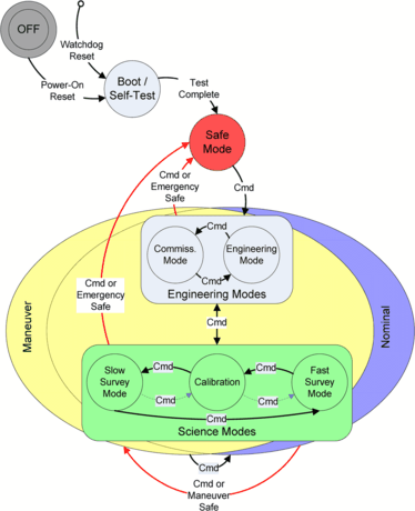
CIDP FSW modes of operation, state diagram
-
The FEEPS Processing Task processes raw data received from the FEEPS instrument into housekeeping, survey, and burst telemetry for later downlink.
-
The Science Data Processing Task receives trigger data from the instruments and computes a data quality value for the high-resolution burst data recorded during the last 10-second interval.
-
The Idle/Memory Scrubber Task reads and rewrites the EDAC-protected memory in the background to prevent correctable errors from becoming uncorrectable errors.

4.4 Instrument Suite Redundancy Approach
The Instrument Suite employs three types of redundancy: cross-strap redundancy, block redundancy and functional redundancy, the block and functional redundancy within the Instrument Suite is shown pictorially in Fig. 33. The level of redundancy selected is tailored to balance overall system reliability, development cost and the operational concept. The general approach is to provide hardware redundancy (cross-strap or block) at points of data concentration (CIDP, FIELDS CEB, and FPI IDPU) and functional redundancy where there are multiple overlapping measurement schemes. A view of the redundancy from an electrical interfaces standpoint can be seen in Fig. 33.
The hardware redundancy scheme chosen for various parts of the instrument suite depended on the complexity of the inter-component interfaces, the level of segmentation provided by those components, and the operational life of those components. For example, cross-strapped redundancy was selected for the S/C to CIDP operational interfaces. This was a natural outgrowth of the CIDPs place in the overall architecture:
-
The CIDP is a critical function for the entire mission. Thus, the critical functionality of the CIDP required the high-reliability provided by fully redundant sides.
-
The CIDP completely isolates the IS from the S/C. Thus, the functional isolation between the S/C and the IS allowed S/C to CIDP cross-strapping without affecting the rest of the IS.
-
The CIDP communicates with the S/C via a SpaceWire interface and is powered by the primary bus power—the SpaceWire standard supports ease of cross-strapping (as does the ability to wire-OR power).
The chosen cross-strap redundancy configuration of the S/C to CIDP operational interfaces allows a failure on one of spacecraft component sides to be handled without impacting operation of the fully functional CIDP side. The converse is also true, a failure in a CIDP side does not require a change on the S/C side.
In contrast, the actuator power service provided to the CIDP is block redundant; that is, the primary spacecraft component provides actuator bus power only to the primary CIDP, with the same configuration on the redundant side. This simplification in the cross-strap configuration is justified by the fact that the actuator bus is only used in early mission prior to ADP and SDP deployments and does not need to have a long operational life.
The CEB and IDPU are internally redundant data concentrator boxes, similar to the CIDP, but the data interfaces between the CIDP and CEB/IDPU are more complicated than the S/C to CIDP SpaceWire interface, requiring more complicated OR’ing for a cross-strapped configuration. Thus, we chose to configure CIDP to CEB/IDPU redundancy in block mode; that is, the CIDP-A is tied to only CEB-A and IDPU-A, while CIDP-B is tied to only CEB-B and IDPU-B. A failure on a given side in the CEB, the IDPU, or the CIDP requires that an Instrument Suite side change affecting all three components be made. This block redundancy is chosen to provide a large improvement in reliability without overly complicating the operational concept. Because the Instrument Suite is isolated from the rest of the spacecraft by the CIDP, and the CIDP to S/C interfaces are cross-strapped, the requirement to change Instrument Suite sides in a block will not affect the spacecraft configuration.
During development, it was found that acceptable mission reliability, in the presence of some failures, could be supported on the basis of instrument functional redundancy. A “tolerable failures” table was developed to demonstrate which instrument failures could be allowed without loss of mission science among four observatories, as shown in Table 3. There is significant overlap between instrument types and instrument observation schemes allowing a great deal of graceful degradation. For this reason, each instrument is internally non-redundant.
4.5 Instrument Suite Integration and Test (I&T)
Instrument Suite integration started after the receipt of the first flight instrument deck at SwRI with the installation of the electrical harnesses, purge system, and thermal control hardware. The integration began with the installation of a flight CIDP and the delivery of the ASPOC instruments from Austria. In addition, pre-integration testing was performed with the HPCA Flight Model #1. Standard integration flows included performing incoming inspection, magnetic screening and safe-to-mate on all hardware prior to mechanical installation on the deck. Integration tests included initial power application, in-rush measurements and aliveness. Finally, a limited performance test was performed. Instrument Suite Deck #1 was partially integrated at SwRI.
To collocate the GSFC and SwRI I&T teams, minimize hardware shipments and mitigate the high cost of developing an environmentally controlled transporter, the MMS team decided to de-integrate and ship the instruments separately from the deck. The SwRI I&T team moved its operation to GSFC to minimize the logistics of delivering a large set of flight components from GSFC and UNH to San Antonio. Once instrument integration was completed, a full Instrument Suite comprehensive performance test (CPT) was performed. An acceptance review was conducted prior to the delivery of each deck for integration with the spacecraft deck. Late hardware deliveries were mitigated by the use of engineering models (EM) and flight models that were not yet qualified. Figure 37 illustrates the typical integration flow for Instrument Suite I&T.

Typical integration flow for instrument suite deck processing
5 Mission Development
The MMS Project recognized from the onset that the construction, integration, and testing of four observatories represented unique challenges that GSFC, and indeed few NASA missions had ever faced before. Beginning prior to the preliminary design review the Project focused on developing plans that were resilient to late deliveries of a given subsystem or instrument. It was recognized that the build of multiple flight copies of every subsystem and instrument would offer great flexibility during the I&T phase since if a single unit encountered problems or delays a working unit could be substituted to continue I&T while it was repaired. Conversely, the discovery of a systemic design or workmanship issue could impact all observatories and have an amplified effect on the mission schedule. To plan for this the Project postulated a number of worse-case scenarios and exercised detailed re-planning exercises which were presented at the major independent milestone reviews.
The testing and qualification of four identical observatories presented the Project with the challenge of adapting GSFC standard practices and requirements that were developed to build single copies of unique spacecraft to the multiple spacecraft paradigm. The Project strove to strike the right balance between necessary testing, and the time and cost involved in “by the book” testing four duplicate spacecraft. The MMS Project devoted considerable effort to differentiating design qualification testing from testing activities that were primarily workmanship tests. It was also essential that the Project develop practices that rigorously identified and tracked the inevitable small configuration differences among the observatories and take that into account in decisions regarding necessary testing. The execution of the build and testing of the subsystems and instruments and then the observatories that resulted from this planning is described in the following sections.
5.1 Flight Hardware Manufacturing
The MMS manufacturing effort was large, diverse and distributed among over 40 organizations including contractors, non-profit organizations, universities and internationals. A staggering total of 638 flight components and boxes were built and delivered to GSFC and SwRI for integration into four observatories. Firm, fixed price contracts were competitively awarded to vendors for off-the-shelf spacecraft components such as solar arrays and star sensors. Spacecraft avionics boards were designed by GSFC, and Instrument Suite avionics were designed by SwRI and other instrument providers.
A parts control program was implemented per the Level 2 requirements of GSFC EEE-INST-002. De-rating analyses for EEE parts was in accordance with GSFC EEE-INST-002. A common parts buy program was implemented for cost efficiency as well as to limit the number of different part types and purchasing lots needed. The MMS Project experienced some part design and workmanship issues resulting in failures after their screening and integration into instruments, in particular with opto-couplers. An extensive screening test program at the instrument level was implemented for all FPI instruments in order to reduce the risk of on-orbit failure of opto-couplers. Additional long duration risk assessment testing was performed on a number of flight spare opto-couplers.
Engineering test units (ETUs) were built for most components and they proved to be invaluable as manufacturing pathfinders and for troubleshooting issues. It became apparent during the ETU phase that the manufacturing effort for flight avionics boards needed to be distributed among more contractor fabrication houses to prevent schedule bottlenecks. Quality issues were also identified during the ETU phase. These led the Project to seek out fabrication houses that utilized automated board manufacturing techniques. In general, ETUs were subjected to environmental tests at qualification levels.
To save cost, flight spares were kitted but only a limited number of spares were built. International partners elected to build flight spares. The decision to build a limited number of spares proved to be cost effective as no delays due to lack of spares were encountered. Flight spares were swapped in for an EDI, an SCM pre-amp and 2 SDP flight units. None of the spare spacecraft components or kits was needed for flight with the exception of some isolated parts that were used to replace failed parts and one spare battery that was used to replace the flight unit when launch was delayed.
MMS followed traditional practices of testing instruments and spacecraft components at the board level, subassembly level, and instrument/component level prior to their delivery to I&T. Board level testing consisted of full functional testing at room, hot and cold temperatures. The sheer number of FPI boards required for this mission drove the FPI team to develop automated board testing stations both at GSFC for board testing and at SwRI for HVPS testing.
Most flight components were subjected to EMI, magnetics, vibration and thermal vacuum testing before delivery to I&T. In general, first flight units were subjected to proto-flight vibration levels and subsequent units were vibration tested at acceptance levels. All units were tested to proto-flight thermal vacuum levels. FPI instruments were subjected to electron and ion beam testing. Likewise, HPCA, EDI, EIS and FEEPS were each tested with the appropriate sources in order to verify their performance.
5.2 Observatory Integration & Test
The MMS I&T effort was based on the parallel processing of 1) the spacecraft bus, 2) the Instrument Suite, and 3) the thrust tube/propulsion system. This allowed progress to be made for quite some time on all three elements before they were integrated together into an observatory and work became more serial in nature.
Both a spacecraft and Instrument Suite FlatSat comprised of engineering models were built to dry-run all test scripts before execution on the flight system. Risk reduction spacecraft and Instrument Suite decks were built for early box and harness routing checks. Both a spacecraft C&DH and CIDP simulator were built for interface verification. A CIDP Engineering Model was utilized to perform early interface testing at instrument provider locations. Both the FPI and FIELDS teams performed Instrument Suite tests prior to their delivery to SwRI.
Instrument Suite 1 was partially assembled at SwRI but was de-integrated and shipped to GSFC where integration was completed. A decision was made by the Project to accelerate the co-location of SwRI personnel at GSFC and save effort in shipping decks back and forth, so this Instrument Suite was de-integrated, shipped and re-integrated at GSFC. Subsequent Instrument Suites were integrated at GSFC. A CPT and burst tests were run on each Instrument Suite prior to its delivery to the GSFC I&T team. Figure 38 shows Instrument Suite #1 prior to its delivery to GSFC I&T.

Instrument suite #1
The spacecraft bus components were integrated at GSFC. Figure 39 shows the first spacecraft bus prior to its integration with the thrust tube/propulsion system.

Spacecraft bus #1
The thrust tube/propulsion system consists of a mechanical thrust tube with four propulsion tanks located within the tube, propulsion system lines, propulsion components and thermal components. They were integrated in a staggered fashion with all welding and X rays performed at GSFC. Prior to its delivery and mounting on the spacecraft deck, the thrust tube/propulsion system was subjected to a proof pressure test and a thermal heater verification test.
Significant effort was required for MMS I&T planning due to the complexity of managing the staggered development of four observatories during the I&T campaign. It was recognized early on that the Project needed to maintain schedule flexibility and resiliency to late instrument and spacecraft component deliveries in order to meet key schedule milestones. With this is mind, MMS was designed such that any instrument could be removed or integrated at the observatory level without de-integration of the Instrument Suite. This proved to be a wise decision because a number of instruments were integrated and de-integrated after Instrument Suite delivery to the spacecraft bus. The MMS schedule was continuously managed to minimize impacts to the critical path by swapping components between observatories and re-ordering the I&T flow for integrating components in order to accommodate late deliveries.
With four observatories to build and test at GSFC, the MMS Project encountered some unique challenges. The spacecraft are far from small, with each observatory carrying 25 instruments. In order to keep track of multiple builds, the Project utilized enhanced configuration control processes to ensure traceability for each observatory. In order to build observatories in a staggered fashion, MMS personnel were required to multi-task with board manufacturing, component testing and observatory integration and testing occurring in parallel.
Observatories were subjected to aliveness tests, functional tests, and CPTs. Aliveness tests involved turning on all hardware. Functional tests turned on hardware and checked all copper paths. CPTs were longer tests that checked the performance of each spacecraft subsystem and instrument. RF compatibility testing was performed on all observatories for the DSN, Space Network (SN), and Universal Space Network (USN).
A pre-environmental CPT was run for Observatories #1, 2, and 3, and a pre-environmental Functional test was run for Observatory #4. A post-environmental CPT was run for Observatories #1, 2, and 4, and a post-environmental Functional test was run for Observatory #3. Functional tests were performed on all observatories after shipment to the launch site and after transport to the Vertical Integration Facility (VIF).
5.3 Observatory Environmental Testing
The MMS observatories were subjected to environmental testing consisting of acoustics, vibration, shock, electromagnetic interference/electromagnetic control (EMI/EMC), and thermal vacuum tests. Qualification tests were performed only once. Other tests were performed on every observatory in an attempt to uncover workmanship issues. Observatories were generally in flight configuration for environmental tests, but there were a few exceptions where mass models were substituted for FPI and EDI instruments due to their late deliveries. Table 4 summarizes environmental tests performed on observatories and Table 5 lists exceptions to observatory flight configuration during each test.
Mechanical testing comprised of strength, acoustic, vibration, shock and mass properties tests. Strength qualification testing was performed in a static facility and with a centrifuge test on a single thrust tube, as shown in Fig. 40. Acoustic testing was performed on all observatories to qualify the structure in the high frequency dynamic environment, prior to thermal vacuum testing, as shown in Fig. 41. A mini-stack acoustics test was performed on two observatory structures mated together. Both wet (with deionized water simulating the propulsion fuel load) and dry vibration tests were performed on Observatory #1. A stacked vibration test was performed on all observatories to verify structural dynamics in a launch configuration. Shock testing was performed on a mini-stack of Observatories #1 and #2 with a GSE plate on top, as well as after full stacked vibration testing. Mass properties tests were performed on all observatories.

Thrust tube centrifuge testing at GSFC

Observatory #1 acoustics testing at GSFC
A risk reduction EMI/EMC test was performed on Observatory #1 to provide an early performance verification under worse case conditions (without a Faraday cage). A qualification EMI/EMC test (including emission and susceptibility) was performed on Observatory #3. Due to the robust component level EMI verification program and successful risk reduction test, abbreviated EMI/EMC tests were performed on Observatories #1, #2 and #4. Figure 42 shows Observatory #4 being prepared for EMI/EMC testing at GSFC. Figure 43 shows Observatory #4 during a magnetics swing test.

Observatory #4 being prepared for EMI/EMC testing at GSFC

Observatory #4 magnetics swing testing
Thermal vacuum/thermal balance testing was performed at the Naval Research Laboratory (NRL) on all observatories to demonstrate repeated system-level performance at the extremes of the flight predicted temperatures. A separate thermal balance phase was performed on Observatory #2 which included a hot to cold cycle that was counted as one of the four cycles performed. Observatories #1, #3, #4 were subjected to four cycles without a separate thermal balance phase, but had mini thermal balance points on hot and cold plateaus that were compared to the thermal balance done on Observatory #2. Figure 44 shows Observatory #2 being prepared for thermal vacuum testing at NRL.

Observatory #2 being prepared for thermal vacuum testing at NRL
5.4 Mission Simulations and Mission Operations Development
Extensive mission simulations were performed prior to launch. Mission readiness tests (MRTs) were run on the spacecraft FlatSat, the Instrument Suite FlatSat, on a mission training simulator (MTS) and on observatories. MRTs were used to verify operational processes, procedures, and train personnel in an operational environment, including nominal and contingency scenarios. A total of 45 MRTs were conducted and more than 500 h of observatory time was devoted to MRTs.
Ground system readiness tests (GSRTs) were run to verify that the Ground System met all functional and performance requirements. End-to-end tests were initiated with data flow from observatories all the way through to the ITFs. Data flow tests were conducted between the MOC, DSN, SN, and USN. Multiple operations readiness tests were conducted with all network assets. A total of 16 GSRTs were conducted.
6 Launch and Commissioning
MMS was shipped for launch processing at Astrotech in Titusville, Florida. Functional tests were performed on all observatories after shipment. Observatories were fueled, stacked and encapsulated at Astrotech prior to their shipment to the VIF at Space Launch Complex 41 at Cape Canaveral Air Force Station. Fully stacked, MMS had a nominal mass of 5398 kg. Functional and integrated system tests with the launch vehicle were performed at the VIF prior to roll out to the pad.
MMS was launched on March 12, 2015 at 10:44 pm EDT by a United Launch Alliance (ULA) Atlas-V series 421 launch vehicle from LC 41. The MMS launch vehicle was configured with a 4-m (14-ft) diameter extra extended payload fairing (XEPF), two solid rocket boosters (SRBs), and a single engine Centaur upper stage. The four observatories, designated MMS-1, MMS-2, MMS-3, and MMS-4, were launched in stacked configuration with MMS-1 attached to the Centaur. The Centaur was responsible for spinning the stack up to 3 rpm prior to separation, starting with MMS-4 and ending with MMS-1 with separations occurring every 5 minutes. Prior to separating, each observatory transmitter was turned on via relative time sequence (RTS) commands triggered by separation signals beginning with fairing jettison. The MMS observatories were inserted into orbits with 585 km perigee height and between 70,061 km and 70,126 km apogee height. Figure 45 shows the MMS ground track and communication station coverage for the Atlas V/Centaur through MMS separation.

MMS ground track
The MMS commissioning phase lasts approximately 165 days, concluding when the orbit apogee reaches a GSE time of 1800 h ±1 h. The MOC and SOC follow a fully integrated Commissioning Timeline to perform a number of activities. The SOC operate instruments using the Telemetry and Command system located at LASP. ITFs are located at the SOC during the commissioning of their respective instrument. The MOC turns over commanding to the SOC once the communications links have been established, the command capability has been verified and all other nominal pass activities have been executed. Ground contacts are achieved with the DSN, SN, and NEN stations.
Spacecraft activities performed by the MOC are categorized as mostly passive spacecraft subsystem activities and maneuvers. A total of 32 maneuvers are planned during commissioning including calibrations, perigee raise, precession, spin-up, orbit stabilization and formation initialization maneuvers.
Instrument Suite commissioning activities performed by the SOC are categorized as instrument low voltage activation, instrument high voltage activation, deployments, and transition to routine operations and special calibrations. A total of 156 instrument activation events are performed per observatory. Deployments performed during commissioning include ADP receiving element deployments, Mag boom deployments, SDP boom deployments, ADP boom deployments, and EIS door open. During the SDP deployment campaign, the observatory spin rate is increased higher than the nominal 3 rpm seen during the routine mission.
For an approximate 5-week period starting May 12, 2015, MMS encounters an eclipse of greater than 2 h in a given orbit. Instrument activities are constrained during this eclipse period with some instruments powered off.
The Instrument Suite will systematically go through a series of tests to identify any interference between individual instruments. After the interference campaign but prior to the start of the nominal science mission, the Instrument Suite will transition to executing routine ATS commands. During commissioning, all burst data is either retrieved or selectively discarded. As the Instrument Suite transitions to routine operations, burst data will automatically be discarded unless it is specifically selected for retrieval.
7 Project Performance
The MMS Project performance was impacted by a number of external situations. Due to clean room facility conflicts (unforeseen at time of confirmation), the MMS Project was required to fund the construction of a new 4300 ft2 clean room. Thermal vacuum facility conflicts also forced the Project to ship observatories to NRL for thermal vacuum testing. Finally, the government shutdown in September, 2013 resulted in a month’s lost work and a corresponding slip in the MMS Launch Readiness Date. Although the government shutdown resulted in a LRD slip of one month to November, 2014, due to the crowded launch manifest schedule the Current Launch Schedule Review Board moved the MMS launch to March, 2015.
The MMS Project is currently predicted to be completed with a total budget increase of 3.7 % over the Agency Baseline Commitment (ABC) of $1082.6M established at MMS confirmation in June, 2009. If the MMS budget is adjusted for external impacts, the Project was implemented with a 2.6 % cost savings to the ABC.
Abbreviations
- ACS:
-
Attitude Control System
- ADC:
-
Analog-to-Digital Converter
- ADP:
-
Axial Double Probe
- AFG:
-
Analog Flux Gate
- AMS:
-
Acceleration Measurement System
- ASPOC:
-
Active Spacecraft Potential Control
- ATS:
-
Absolute Time Sequences
- C&DH:
-
Command and Data Handling
- CCSDS:
-
Consultative Committee for Space Data Systems
- CEB:
-
Central Electronics Box
- CFDP:
-
CCSDS File Delivery Protocol
- CGS:
-
Core GPS Software
- CIDP:
-
Central Instrument Data Processor
- cPCI:
-
compact Peripheral Component Interconnect
- CPT:
-
Comprehensive Performance Test
- CSA:
-
Component Subassembly
- DB:
-
Digital Board
- DES:
-
Dual Electron Spectrometer
- DFG:
-
Digital Flux Gate
- DIS:
-
Dual Ion Spectrometer
- DSC:
-
Diode Switch Card
- DSN:
-
Deep Space Network
- DSS:
-
Digital Sun Sensor
- ECSS:
-
European Cooperation for Space Standardization
- EDI:
-
Electron Drift Instrument
- EEE:
-
Electrical, Electronic, and Electromechanical
- EEPROM:
-
Electrically Erasable Programmable Read Only Memory
- EGSE:
-
Electrical Ground Support Equipment
- EIS:
-
Electron Ion Spectrometer
- EPS:
-
Electrical Power Subsystem
- ETU:
-
Engineering Test Unit
- EVD:
-
Engine Valve Driver
- FDOA:
-
Flight Dynamics Operations Area
- FEA:
-
Front-end Electronic Assembly
- FEEPS:
-
Fly’s Eye Energetic Particle Sensor
- FET:
-
Field Effect Transistor
- FOV:
-
Field of View
- FPGA:
-
Field Programmable Gate Array
- FPM:
-
Flight Purge Manifold
- FPI:
-
Fast Plasma Investigation
- FSW:
-
Flight Software
- GDS:
-
Goddard Dynamic Simulator
- GDU:
-
Gun Detector Unit
- GEONS:
-
Goddard Enhanced Onboard Navigation System
- GPS:
-
Global Positioning System
- GSE:
-
Geocentric Solar Ecliptic
- GSEOS:
-
Ground Support Equipment Operating System
- GSFC:
-
Goddard Space Flight Center
- HOP:
-
High-Output Paraffin
- HPCA:
-
Hot Plasma Composition Analyzer
- HVPS:
-
High Voltage Power Supply
- IDPU:
-
Instrument Data Processing Unit
- I&T:
-
Integration & Testing
- IP:
-
Intellectual Property
- ITF:
-
Instrument Team Facility
- LASP:
-
Laboratory for Atmospheric and Space Physics
- LVDS:
-
Low Voltage Differential Signaling
- LVPS:
-
Low Voltage Power Supply
- MLI:
-
Multi-Layer Insulation
- MMM:
-
Mass Memory Module
- MMS:
-
Magnetospheric Multiscale Mission
- MOC:
-
Mission Operations Center
- NEN:
-
Near Earth Network
- OM:
-
Output Module
- OSR:
-
Optical Solar Reflector
- PAB:
-
Power Analog Board
- PMC:
-
Power Monitor Card
- PSE:
-
Power System Electronics
- PWM:
-
Pulse Width Modulation
- RF:
-
Radio Frequency
- ROI:
-
Region of Interest
- RTEMS:
-
Real Time Executive for Multiprocessor Systems
- RTS:
-
Relative Time Sequences
- S/A:
-
Safe/Arm
- SAM:
-
Solar Array Module
- SCID:
-
Spacecraft ID
- SCM:
-
Search Coil Magnetometer
- SDP:
-
Spin-plane Double Probe
- SOC:
-
Science Operations Center
- SN:
-
Space Network
- SwRI:
-
Southwest Research Institute
- TAI:
-
Temps Atomique International (International Atomic Time)
- TP-HPDB:
-
Test Panel-Heater Power Distribution Box
- USO:
-
Ultra Stable Oscillator
- USN:
-
Universal Space Network
- VIF:
-
Vertical Integration Facility
References
D.N. Baker et al., Magnetospheric multiscale instrument suite operations and data system. Space Sci. Rev. (2015, this issue). doi:10.1007/s11214-014-0128-5
W. Bamford et al., GPS navigator for the Magnetospheric Multiscale Mission, in Proceedings of the 22nd International Technical Meeting of the Satellite Division of the Institute of Navigation, ION GNSS 2009, Savannah, GA (2009)
J.L. Burch et al., MMS overview and science objectives, Space Sci. Rev. (2015, this issue)
J.R. Carpenter, In: 2009 AAS/AIAA Astrodynamics Specialist Conference Special Session: Flight Dynamics for Magnetospheric Survey Missions, AAS 09-323 thru AAS 09-331, Pittsburgh, PA (2009)
S.A. Curtis, The Magnetospheric Multiscale mission—resolving fundamental processes in space plasmas. Report of the NASA Science and Technology Definition Team (NASA/TM-2000-209883) (1999)
N. Fatemi, J. Lyons, M. Eskenazi, Qualification and production of Emcore ZTJ solar panels for space missions, in 2013 IEEE 39th Photovoltaic Specialists Conference, PVSC, Tampa, FL (2013). doi:10.1109/PVSC.2013.6745052
S.A. Fuselier et al., Magnetospheric Multiscale science mission profile and operations. Space Sci. Rev. (2014, this issue). doi:10.1007/s11214-014-0087-x
C.J. Gramling, Overview of the Magnetospheric Multiscale formation flying mission, in Astrodynamics 2009: Advances in the Astronautical Sciences, Proceedings of the AAS/AIAA Astrodynamics Specialist Conference, Pittsburgh, PA (2010), p. 407
O. Haddad, Remote memory access protocol target node intellectual property, NASA tech. brief, GSC-16467-1, August (2013)
R.A. Klar et al., Performance of the Magnetospheric Multiscale central instrument data handling, in 2013 IEEE Aerospace Conference (2013). doi:10.1109/AERO.2013.6497336
B.H. Mauk et al., The Energetic Particle Detector (EPD) investigation and the Energetic Ion Spectrometer (EIS) for the Magnetospheric Multiscale (MMS) mission. Space Sci. Rev. (2014, this issue). doi:10.1007/s11214-014-0055-5
H. Mulkey, K. Parker, E. Cardiff et al., Delta qualification life tests for the Magnetospheric Multiscale mission radial thruster, in Proceedings of the 47th AIAA/ASME/SAE/ASEE Joint Propulsion Conference & Exhibit, AIAA 2011-611, San Diego, CA (2011). doi:10.2514/6.2011-6111
National Research Council (NRC), Solar System Exploration Survey, 2003, ISBN 0-309-55902-2
C. Pollack et al., Fast plasma investigation for magnetospheric multiscale, Space Sci. Rev. (2015, this issue)
S. Queen, D. Chai, Precision closed-loop orbital maneuvering system design and performance for the Magnetospheric Multi-Scale mission, in 25th International Symposium on Space Flight Dynamics, ISSFD, Munich, Germany, October 19–23 (2015)
S. Queen, S. Benegalrao, N. Shah, Generalized momentum control of the spin-stabilized Magnetospheric Multiscale mission observatories, in 2015 AAS/AIAA Astrodynamics Specialist Conference, August 9–13, Vail, CO (2015)
D. Raphael, R.F. Stone, D.L. Guevera, J.E. Fraction, Command & data handling for the Magnetospheric Multiscale mission, in 2014 IEEE Aerospace Conference (2014). doi:10.1109/AERO.2014.6836373
R. Reynolds, G. Creamer, Global Lyapunov control of spin stabilized spacecraft, in Flight Mechanics Symposium, Greenbelt, MD (2001)
N. Shah, A globally stable Lyapunov pointing and rate controller for the Magnetospheric Multiscale mission (MMS), in AIAA Guidance, Navigation, and Control Conference, August 2011, Portland, OR (2011)
T. Stern, M. Wrosch, E. McNaul, T. Parfet, A. Anders, A. Aldape, J. Lyons, Electromagnetically clean solar array panels for the Magnetospheric Multiscale spacecraft, in 11th International Energy Conversion Engineering Conference, AIAA 2013-4026 (2013)
J.K. Thienel, F.L. Markley, R.R. Harman, Extended Kalman filter for MMS state estimation, spaceflight mechanics, in Advances in the Astronautical Science, Proceedings of the 19th AAS/AIAA Space Flight Mechanics Meeting, vol. 134, Savannah, GA (2009)
K. Torkar et al., Active spacecraft potential control investigation. Space Sci. Rev. (2014, this issue). doi:10.1007/s11214-014-0049-3
R.B. Torbert et al., The FIELDS instrument suite on MMS: scientific objectives, measurements, and data products. Space Sci. Rev. (2014, this issue). doi:10.1007/s11214-014-0109-8
J. Wilmot, Implications of responsive space on the flight software architecture, in AIAA Responsive Space Conference, AIAA-RS4, 2006-6003 (2006)
L. Winternitz, W. Bamford, G. Heckler, A GPS receiver for high-altitude navigation. IEEE J. Sel. Top. Signal Process. 3(4), 541–556 (2009)
D.T. Young, et al., Hot Plasma Composition Analyzer for the Magnetospheric Multiscale mission. Space Sci. Rev. (2014, this issue). doi:10.1007/s11214-014-0119-6
R. Zara, MMS gold plated rings: a passive heat source, in Proceedings of Thermal & Fluids Analysis Workshop, TFAWS 2011, Newport News, VA (2011)
Author information
Authors and Affiliations
Corresponding author
Rights and permissions
Open Access This article is licensed under a Creative Commons Attribution 4.0 International License, which permits use, sharing, adaptation, distribution and reproduction in any medium or format, as long as you give appropriate credit to the original author(s) and the source, provide a link to the Creative Commons licence, and indicate if changes were made.
The images or other third party material in this article are included in the article’s Creative Commons licence, unless indicated otherwise in a credit line to the material. If material is not included in the article’s Creative Commons licence and your intended use is not permitted by statutory regulation or exceeds the permitted use, you will need to obtain permission directly from the copyright holder.
To view a copy of this licence, visit https://creativecommons.org/licenses/by/4.0/.
About this article

Cite this article
Tooley, C.R., Black, R.K., Robertson, B.P. et al. The Magnetospheric Multiscale Constellation. Space Sci Rev 199, 23–76 (2016). https://doi.org/10.1007/s11214-015-0220-5
Received:
Accepted:
Published:
Issue Date:
DOI: https://doi.org/10.1007/s11214-015-0220-5