
Abstract
In this work, the effect of magnetic field, rotation and initial stress on peristaltic motion of micropolar fluid in a circular cylindrical flexible tube with viscoelastic or elastic wall properties has been considered. Runge–Kutta technique are used. Runge–Kutta method is developed to solve the governing equations of motion resulting from a perturbation technique for small values of amplitude ratio. The time mean axial velocity profiles are presented for the case of free pumping and analyzed to observe the influence of wall properties, magnetic field, rotation and initial stress for various values of micropolar fluid parameters. In the case of viscoelastic wall, the effect of viscous damping on mean flow reversal at the boundary is seen. The numerical results of the time mean velocity profile are discussed in detail for homogeneous fluid under the effect of wall properties, magnetic field, initial stress and rotation for different cases by figures. The results indicate that the effect of wall properties, rotation, initial stress and magnetic field are very pronounced. Numerical results are given and illustrated graphically.
1 Introduction
Several solutions with degrees of approximation are available for the peristaltic flow with various consideration of the nature of the fluid, the geometry of the tube, and the propagation waves. Peristalsis is an important mechanism generated by the propagation of waves along the walls of a channel or tube. It occurs in the gastrointestinal, urinary, reproductive tracts and many other glandular ducts in a living body. Gupta [1] discussed the Rayleigh–Taylor instability of a viscous electrically conducting fluid in the presence of a horizontal magnetic field. Afifi and Gad [2] have presented interaction of peristaltic flow with pulsatile magneto-fluid through a porous medium. Eringen [3]. Mahmoud [4] discussed effect of rotation and magnetic field through porous medium on Peristaltic transport of a Jeffrey fluid in tube. Abd-Alla et al. [5] discussed effect of the rotation on waves in a cylindrical borehole filled with micropolar fluid. Mahmoud et al. [6, 7] presented effect of the rotation on wave motion through cylindrical bore in a micropolar porous cubic crystal, and effect of the rotation on plane vibrations in a transversely isotropic infinite hollow cylinder. Renardy [8] studied current issues in non-Newtonian flow. Srinivasacharya et al. [9] investigated the peristaltic pumping of a micropolar fluid in a tube Selverov and Stone [10] investigated the peristaltically driven channel flows with applications toward micromixing. Mekheimer [11] investigated the peristaltic transport of a couple stress fluid in a uniform and non-uniform channels. Xiao and Damodaran [12] have presented a numerical of peristaltic waves in circular tubes. Influence of a magnetic field on heat and mass transfer by natural convection from vertical surfaces in porous media considering Soret and Dufour effects is studied by Postelnicu [13]. Afifi et al. [14] have discussed effect of magnetic field and wall properties on peristaltic motion of micropolar fluid in circular cylindrical tubes. Mahmoud et al. [15] have studied effect of porous media and magnetic field on peristaltic transport of a Jeffrey fluid in an asymmetric channel. Ali et al. [16] described the peristaltic flow of a couple stress fluid in an asymmetric channel. Muthu et al. [17] have analyzed the peristaltic motion of micropolar fluid in circular cylindrical tubes with elastic wall properties then extended their analysis to axisymmetric tube for small values of amplitude ratio using a regular perturbation method. Vajravelu et al. [18] discussed the peristaltic flow and heat transfer in a vertical porous annulus, with long wave approximation. Abd Elnaby and Haroun [19] studied a new model for study the effect of wall properties on peristaltic transport of a viscous fluid. Haroun [20] investigated the effect of Deborah number and phase difference on peristaltic transport of a third-order fluid in an asymmetric channel. A study on the development of a continuous peristaltic micropump using magnetic fluids has been discussed by Kim and Choi [21]. Chen [22] studied by the non-linear stability characterization of the thin micropolar liquid film flowing down the inner surface of a rotating vertical cylinder. Eldabe et al. [23] investigated the mixed convective heat and mass transfer in a non-Newtonian fluid at a peristaltic surface with temperature dependent viscosity. The aim of this paper, is to study the effect of magnetic field, rotation and initial stress on peristaltic motion of micropolar fluid in a flexible tube. Here the governing equations are nonlinear in nature, we used a regular perturbation method to obtain linearized system of coupled differential equations which are then solved numerically using Runge–Kutta method. Results have been discussed for time mean velocity profile to observe the magnetic field, rotation and initial stress in the presence of micropolarity effects. The numerical results displayed by figures.
2 Formulation of the problem
We consider the axisymmetric flow of unsteady incompressible micropolar fluid in an infinite rotating tube of uniform radius d under effect of magnetic field H 0, with sinusoidal waves travelling along the boundary of tube with speed c, small amplitude a, the constant angular velocity Ω and wavelength λ (Fig. 1). The wall is assumed to be a flexible membrane.

Geometry of cylindrical tube with peristaltic wave motion of wall
The governing equations for the peristaltic motion of an incompressible micro polar fluid in the circular cylindrical coordinates (R,Θ,Z) are [19].
-
(i)
The equation of continuity
$$ \frac{\partial {U}}{\partial R}+\frac{\partial W}{\partial Z}+\frac{U}{R} =0,$$(1) -
(ii)
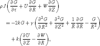
The equations of motion for micro-polar fluid medium
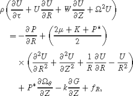 (2)
(2)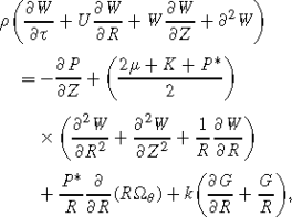 (3)
(3) (4)
(4)


where U,W, are velocity components in the R and Z directions respectively, G is the component of micro-rotation in the Θ direction, P is the pressure, P ∗ is the initial stress, τ is time, ρ denotes the density, μ is dynamic viscosity coefficient. f R is defined as Lorentz’s force, which may be written as
μ ∗ is the magnetic permeability, H 0 is the intensity of the uniform magnetic field, parallel to R-axes, J is micro-inertia constant, k and γ are the viscosity coefficients of micropolar fluid. At the boundary, the fluid is subjected to the motion of the wall which is of the form:
where ξ is the radial displacement from mean position (d) of the wall, as in Fig. 1. It will be assumed that the wall is inextensible and the particles on the wall have no longitudinal displacement and only their lateral motions normal to the undeformed positions occur. Further, it is assumed that the micro-rotation at the wall is zero [19]. Thus we have no slip and no spin conditions on the wall as:
Using the theory of stretched membrane with viscous damping force, suggested the dynamic boundary condition at the axisymmetric motion of the flexible wall [20]. This dynamic boundary condition at R=d+ξ(Z,τ) gives \(\frac{\partial P}{\partial Z}=\frac{\partial L(\zeta )}{\partial Z}\). Using (3), we get

where \(L=-T\frac{\partial ^{2}}{\partial Z^{2}}+m\frac{\partial ^{2}}{\partial \tau ^{2}}+C\frac{\partial }{\partial \tau }\), T is the tension in the membrane, m is the mass per unit area and C is the coefficient of viscous damping force. Further, it is assumed that the velocity and the microrotation be finite at R=0.
Introducing stream function ψ as \(U=\frac{1}{R}\frac{\partial \psi }{\partial Z}\), \(W=-\frac{1}{R}\frac{\partial \psi }{\partial R}\) and eliminating the pressure from (2) and (3) the resulting equations of motion, after ignoring the microinertia effects, can be written in non-dimensional form as


where \(\nabla ^{2}=\frac{\partial }{\partial r^{2}}+\frac{\partial }{\partial z^{2}}+\frac{1}{r}\frac{\partial }{\partial r}\) and the following non-dimensional quantities are defined using d as characteristic length and c as characteristic velocity

The non-dimensional boundary conditions at r=1+η(z,t) are given in the following form:
and

where:

and

With non-dimensional parameters defined as:

The parameters ε,α and Re are the fundamental quantities called amplitude ratio (ratio of amplitude to mean radius of the cylindrical wavy wall), wave number (slope parameter) and Reynolds number respectively, as observed in the classical peristaltic flow K 2,K 3 and m 1 are the non-dimensional quantities related to the wall motion through the dynamic boundary condition (11). The parameters K 2 and K 3 represent the dissipative and rigidity feature of wall respectively, where as m 1 indicates the stiffness property of wall, K 2=0 implies that the wall move up and down with no damping force on it and hence indicates the case of elastic wall.
The parameters μ 1 and M are the non-dimensional quantities due to micropolar fluid flow. The number μ 1 characterizes the coupling of (8) and (9). As k tends to zero, μ 1 becomes zero and (8) and (9) are uncoupled. Further when k and γ are zero, that is, when μ 1 becomes zero and M tends to infinity, (8) and (9) reduce to the classical Navier–Stokes equations.
3 Solution of the problem
It may be noted that the flow is quite complex because of nonlinearity of the governing equations and the dynamic boundary condition. Thus to solve (8) and (9) for the velocity field and the microrotation component, we attempt an approximate solution for Ψ and g as a power series in terms of ϵ. Thus, Ψ and g are taken in the following form:
Substituting (12) in (8) and (9) and comparing the coefficients of like powers of ϵ on both sides of the equations, we obtain sets of the governing equations and boundary conditions for Ψ0,Ψ1,Ψ2,… and g 0,g 1,g 2,… . It may be noted that for ϵ=0, the zeroth order equations correspond to Hagen–Poiseuille flow of micropolar fluid in a tube.
The first and second order governing equations and the corresponding boundary conditions are given by


where:


Further, the governing equations and boundary conditions for the first order flow quantities suggest the following form for Ψ1 and g 1


where the asterisk denotes complex conjugate. Substituting (21) and (22) in the governing equations of Ψ1 and g 1 and separating the harmonics, we have the following governing equations for ϕ 1 and ξ 1:


where

The boundary conditions reduce to:


where two more conditions will be taken, from the assumption that flow is axisymmetric at r=0. In these equations the superscripts, that is, the number within the parentheses indicates the derivative with respect to r (for example, \({f}^{2}\equiv \frac{{d}^{2}f}{{dr}^{2}}\)). The equations governing \(\phi ^{*}_{1}\) and \({\xi }^{*}_{1}\) are conjugate to (23) and (26).
Similarly for Ψ2 and g 2, we assume the solution of the form


Our objective here is to calculate the time mean flow for the case of pure peristalsis (free pumping). The time mean flow w(r) is defined as the axial velocity averaged over the period of oscillation t ∗ of the wave propagation imposed on the flexible wall,

As mentioned earlier, for free pumping case and Ψ0(r)=0 therefore,
In the following, we shall find ϕ 20. Substituting (27) and (28) in (17)–(20), we have the following equation for ϕ 20 and ξ 20:


with boundary conditions


To obtain ϕ 20 and ξ 20 we shall first solve for ϕ 1 and ξ 1. Since it is not possible to get closed form solution, we solve (23) and (24) to get ϕ 1 and ξ 1 numerically, using Runge–Kutta method. Solution procedure for getting ξ 1(r) and ϕ 1(r). Using (23) and (24), we have the governing equation for ξ 1 as:

The boundary conditions are


where:

For the solution of ϕ 1, we substitute the solution of ξ 1 in (23) and solve that with the following boundary conditions:


Solution procedure for ξ 20(r) and ϕ 20(r). From (30) and (31) we get equation for ξ 20 and boundary conditions as:


where:


Now, we solve this system of (30)–(31) using the known ξ 20 with the boundary conditions


and the other two boundary condition given in (32) and (34).
4 Numerical results and discussion
In order to observe the quantitative effects of various parameters involved in the analysis, the time mean velocity at the boundaries of the tube, the time mean velocity perturbation function is calculated for various values of the rotation, magnetic field, initial stress and wall properties and some important results are displayed graphically in Figs. 2–9. It may be noted that in the absence of micro-polar fluid parameters the present analysis reduces to approximate analytical solution of peristaltic flow of a Newtonian fluid in cylindrical tubes with wall properties [3]. Therefore, the present Rung–Kutta method has been validated against the analytical results [3] In order to illustrate theoretical results obtained in the preceding section, we now present some numerical results. The physical data for which is given as m 1=0, k 2=0, k 3=1.0, ϵ=0.01, M=1.0, μ 1=4.0. Figure 2 represents the variation of w(r) with r for various values of the magnetic field at Ω1=0.5 and P ∗=0.3. The numerical results indicate that, w(r) decreases with increasing r and increases with increasing of magnetic field H 0. It is noted that damping may cause the time mean velocity reversal at the walls, which is not possible in the elastic case. Figure 3 shows the variation the time mean velocity profile w(r) across the rotation Ω1 for different values of H 0 at P ∗=0.3. The results reveal that, w(r) increases with increasing rotation and magnetic field H 0. Figure 4 shows the variations of the time mean velocity profile w(r) across the initial stress P ∗ for different values of H 0 at Ω1=0.5. It is seen that w(r) increases with decreasing initial stress P ∗ and magnetic field H 0. Figure 5 shows the variation the time mean velocity profile w across the wave number α in the circular cylindrical tubes for different values of H 0 at Ω1=0.5 and P ∗=0.3. It is observed that w(r) increases with increasing α and H 0. Figure 6 shows the variation of the time mean velocity profile w(r) across the intensity of the uniform magnetic field H 0 for different values of Ω1 at P ∗=0.3. It is observed that w(r) increases with increasing magnetic field H 0 and rotation Ω1. Figure 7 shows the variation of the time mean velocity profile w(r) with r and different values of μ 1 for H 0=0.3, P ∗=0.3, Ω1=0.5, M=1.0, Re=1.0. It is seen that, increase in the micropolar viscosity coefficient (k) reduces the mean velocity, w(r) is almost constant. Figure 8 shows variation of the time mean velocity profile w(r) with r and different values of Reynolds number Re for H 0=0.3, P ∗=0.3, Ω1=0.5, M=1.0, μ 1=4.0. It is observed that the time mean velocity decreases with increasing Re. Figure 9 shows variation of the time mean velocity profile w(r) with r and different values of M for H 0=0.3, P ∗=0.3, Ω1=0.5, Re=1.0, μ 1=4.0. It is observed that the time mean velocity increases with increasing parameter M. The results indicate that the effect of rotation, magnetic field, initial stress, viscosity and Reynolds number are very pronounced. The results are compared with approximate analytical solution given in [3]. The comparison plots are presented in Figs. 2–9. It may be noted that the maximum error between analytical and numerical solution is less than 0.357×10⁻³.

Variation of the time mean velocity profile w with the radial r for H 0=0.1, 0.3, 0.5, 0.7, P ∗=0.3, Re=1.0 and Ω1=0.5

Variation of the time mean velocity profile w(r) with the Ω1 for H 0=0.1, 0.3, 0.5, 0.7, Re=1.0 and P ∗=0.3

Variation of the time mean velocity profile w(r) with the initial stress P ∗ for H 0=0.1, 0.3, 0.5, 0.7, Re=1.0 and Ω1=0.5

Variation of the time mean velocity profile w(r) with the wave number α for H 0=0.1, 0.3, 0.5, 0.7, P ∗=0.3, Re=1.0 and Ω1=0.5

Variation of the time mean velocity profile w(r) with H 0 for Ω1=0.5, 1.0, 1.5, 2.0, Re=1.0 and P ∗=0.3

Variation of the time mean velocity profile w(r) with r and different values of μ 1 for H 0=0.3, P ∗=0.3, Ω1=0.5, Re=1.0

Variation of the time mean velocity profile w(r) with r and different values of Re for H 0=0.3, P ∗=0.3, Ω1=0.5, μ 1=4.0

Variation of the time mean velocity profile w(r) with r and different values of M for H 0=0.3, P ∗=0.3, Ω1=0.5, Re=1.0, μ 1=4.0
5 Conclusions
In the present study an analysis of peristaltic motion of micro-polar fluid in a circular tubes with dynamic boundary condition has been presented for the case of free pumping. The axisymmetric study agrees with peristaltic motion in a two-dimensional channel [3]. It is observed that w(r) increases when the rotation and magnetic field increase and it is decrease with increasing initial stress. Also, the Reynolds number increases with increasing magnetic field, rotation and wave number. The effect of the rotation, initial stress and magnetic field on the w(r) are studied. It is observed that w(r) decreases when μ 1 increases. For non-zero viscous damping, flow reversal is found at the wall of flexible tube. Finally, the results are discussed and illustrated graphically.
References
Gupta A (1962) Rayleigh–Taylor instability of a viscous electrically conducting fluid in the presence of a horizontal magnetic field. Z Angew Math Phys 13:324–329
Afifi NAS, Gad NS (2001) Interaction of peristaltic flow with pulsatile magneto-fluid through a porous medium. Acta Mech 149:229–237
Eringen AC (1966) Theory of micropolar elasticity. J Math Mech 16:1–18
Mahmoud SR (2011) Effect of rotation and magnetic field through porous medium on Peristaltic transport of a Jeffrey fluid in tube. Math Probl Eng 2011:971456
Abd-Alla AM, Mahmoud SR, Matooka BR (2011) Effect of the rotation on waves in a cylindrical borehole filled with micropolar fluid. Int Math Forum 6(55):2711–2728
Mahmoud SR, Abd-Alla AM, Matooka BR (2011) Effect of the rotation on wave motion through cylindrical bore in a micropolar porous cubic crystal. Int J Mod Phys B 25(20):2713–2728
Mahmoud SR, Abd-Alla AM, AL-Shehri NA (2011) Effect of the rotation on plane vibrations in a transversely isotropic infinite hollow cylinder. Int J Mod Phys B 25/26:3513–3528
Renardy M (2000) Current issues in non-Newtonian flows: a mathematical perspective. J Non-Newton Fluid Mech 90:243–259
Srinivasacharya D, Mishra M, Rao AR (2003) Peristaltic pumping of a micropolar fluid in a tube. Acta Mech 161:165–178
Selverov KP, Stone HA (2001) Peristaltically driven channel flows with applications toward micromixing. Phys Fluids 13:1837–1859
Mekheimer KHS (2008) Effect of the induced magnetic field on peristaltic flow of a couple stress fluid. Phys Lett A 372(23):4271–4278
Xiao Q, Damodaran M (2002) A numerical investigation of peristaltic waves in circular tubes. Int J Comput Fluid Dyn 16:201–216
Postelnicu A (2004) Influence of a magnetic field on heat and mass transfer by natural convection from vertical surfaces in porous media considering Soret and Dufour effects. Int J Heat Mass Transf 47:1467–1472
Afifi NA, Mahmoud SR, Al-Isede HM (2011) Effect of magnetic field and wall properties on peristaltic motion of micropolar fluid in circular cylindrical tubes. Int Math Forum 6(27):1345–1356
Mahmoud SR, Afifi NA, Al-Isede HM (2011) Effect of porous media and magnetic field on peristaltic transport of a Jeffrey fluid in an asymmetric channel. Int J Math Anal 5(21):1025–1034
Ali N, Hayat T, Sajid M (2007) Peristaltic flow of a couple stress fluid in an asymmetric channel. Biorheology 44(2):125–138
Muthu P, Rathish Kumar BV, Peeyush C (2001) Peristaltic motion in circular cylindrical tubes: effect of wall properties. Indian J Pure Appl Math 32(9):1317–1328
Vajravelu K, Radhakrishnamacharya G, Radha Krishnamurty V (2007) Peristaltic flow and heat transfer in a vertical porous annulus with long wave approximation. Int J Non-Linear Mech 42:754–759
Abd Elnaby MA, Haroun MH (2008) A new model for study the effect of wall properties on peristaltic transport of a viscous fluid. Commun Nonlinear Sci Numer Simul 13:752–762
Haroun MH (2007) Effect of Deborah number and phase difference on peristaltic transport of a third-order fluid in an asymmetric channel. Commun Nonlinear Sci Numer Simul 12:1464–1480
Kim EG, Choi B (2006) A study on the development of a continuous peristaltic micropump using magnetic fluids. Sens Actuators A, Phys 128:43–51
Chen C (2007) Non-linear stability characterization of the thin micropolar liquid film flowing down the inner surface of a rotating vertical cylinder. Commun Nonlinear Sci Numer Simul 12:760–775
Eldabe NT, El-Sayed MF, Ghaly AY, Sayed HM (2008) Mixed convective heat and mass transfer in a non-Newtonian fluid at a peristaltic surface with temperature dependent viscosity. Arch Appl Mech 78:599–624
Open Access
This article is distributed under the terms of the Creative Commons Attribution Noncommercial License which permits any noncommercial use, distribution, and reproduction in any medium, provided the original author(s) and source are credited.
Author information
Authors and Affiliations
Corresponding author
Rights and permissions
Open Access This is an open access article distributed under the terms of the Creative Commons Attribution Noncommercial License (https://creativecommons.org/licenses/by-nc/2.0), which permits any noncommercial use, distribution, and reproduction in any medium, provided the original author(s) and source are credited.
About this article
Cite this article
Abd-Alla, A.M., Yahya, G.A., Mahmoud, S.R. et al. Effect of the rotation, magnetic field and initial stress on peristaltic motion of micropolar fluid. Meccanica 47, 1455–1465 (2012). https://doi.org/10.1007/s11012-011-9528-8
Received:
Accepted:
Published:
Issue Date:
DOI: https://doi.org/10.1007/s11012-011-9528-8