
Abstract
The safety and serviceability of timber structures are frequently governed by the performance of joints. Bolted joints are a very commonly used form of joints and are effective from the viewpoint of the load–slip characteristics when subjected to a lateral force. The shear strength of a bolted joint is affected by various factors. Some of the factors affecting the shear strength of a bolted joint are classified into four categories in this paper: the material characteristics, geometrical factors, assembly conditions for the bolted joint, and factors that act during its service. This paper reviews the effects of these factors on the shear strength of a bolted joint. Numerous experimental studies were performed on the shear strength of a bolted joint. The effects of these factors on the shear strength varied according to the kind of shear strength and loading direction to the grain. In addition to the experimental investigations, analytical investigations to estimate the shear strength of a bolted joint are also discussed in this paper. Estimations of the yield strengths of bolted joints have been performed by numerous researchers; and in recent years, there has been an increase in studies to predict the load at failure.
Introduction
The performance of a timber structure must be sufficient to preserve life and property. Because this performance, which involves safety and serviceability, is frequently governed by the stiffness and strength of joints, the joints are important components of a timber structure. The number of different types of joints used in timber structures has increased over time. At present, various joints are utilized, including nailed joints, bolted joints, screwed joints, glued joints, glued-in-rod joints, and large-finger joints [1].
Among these, bolted joints are a very commonly used form of joints. Their force-resisting mechanisms can be broadly divided into two types: the tensile type, where the bolted joint resists the force along the axis of the bolt, and the shear type, where the bolted joint resists the force applied perpendicular to the axis of the bolt. The latter is more desirable from the viewpoint of the load–slip characteristics, because the former often causes a rapid decrease in the load at failure.
The load–slip characteristics of a bolted joint subjected to a lateral force are governed by the embedding stress–deformation characteristics of the wood, which crush the wood beneath the bolt, and the bending stress–deformation characteristics of the bolt. In addition to the characteristics of the material, it is well known that the load–slip characteristics of a bolted joint are also affected by the geometric properties and type of joint. Thus, bolted joints have diverse configurations based on the combination of these variables. Because of their diversity and on-site assembly facility, bolted joints are widely applied to timber structures, and numerous studies have been performed on their load–slip characteristics.
The factors affecting the load–slip characteristics of bolted joints have been investigated experimentally, and could be divided into various categories. In this paper, these factors are classified into four categories as follows:
-
Material characteristics—these are mechanical properties of member and bolt such as the embedding strength of the member, yield stress of the bolt, and surface roughness of the bolt.
-
Geometrical factors—this is joint geometry such as the thickness of the member, end distance, and edge distance as shown in Fig. 1. The joint geometry is often expressed as the values of those dimensions divided by the bolt diameter.
Fig. 1 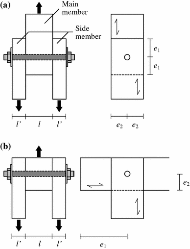
Typical bolted joint with wood side members. a Bolted joint parallel to the grain. b Bolted joint perpendicular to the grain. l thickness of main member, l′ thickness of side member, e 1 end distance, e 2 edge distance
-
Assembly characteristics—these are conditions in assembling the bolted joint such as the difference between the lead hole diameter and bolt diameter, smoothness of the lead hole, and force used to fasten the bolt.
-
Factors that act during its service—these are factors acting in service such as the loading direction in relation to the grain, type of applied force, and moisture content.

This paper gives an outline of the effects of these factors on the strength of a bolted joint subjected to a lateral force. The strengths of bolted joints described in reports include the load at the proportional limit, yield load, ultimate load, maximum load, and load-carrying capacity. However, evaluation method of these strengths sometimes differs with researchers. For example, the ultimate load means maximum load in some report, and those are different in other report. Therefore, the designation of the strength is based on the cited literature.
Analytical approaches have also played important roles in the design of bolted joints. Some analytical studies have been performed to estimate the yield load and load at failure of bolted joints, and the results are reflected in the design codes [2]. This paper also reviews analytical studies on the strength of bolted joints subjected to lateral forces.
Factors affecting shear strength
Factors governing material characteristics
The embedding strength, which is one of the most important material characteristics for bolted joints, is generally obtained in a test, using either the American approach [3] or European approach [4] as shown in Fig. 2. These use different specimen configurations and dimensions [5, 6]. In the American approach, a fastener is placed on a wood specimen with a half-round lead hole, and a uniform force along the fastener length is applied to the wood specimen. In the European approach, a wood specimen and steel support are connected using a fastener, and a force is applied at the ends of the fastener through the steel support. The shapes of the embedding stress–deformation curves parallel to the grain show no difference between these approaches. However, those perpendicular to the grain show a difference in the increase in the load after the yield point [7, 8]. The yield embedding strength can be obtained from tests based on both approaches, but the strength beyond the yield point is obtained only from tests based on the European approach. The embedding strength according to ASTM [3] is calculated using the “5 % offset method,” and that according to EN383 [4] is calculated from the maximum stress up to a 5 mm embedment.

Embedding tests. a American approach. b European approach
The embedding strength of wood increased in proportion to an increase in the wood density, and decreased with an increase in the diameter of the fastener [5, 7, 9, 10]. The regression line of the embedding strength in relation to both the wood density and fastener diameter has been investigated to estimate the embedding strength for design. When the fastener diameter was in the range of 8–30 mm, the embedding strength or embedding strength divided by the density linearly decreased as the fastener diameter increased [7, 9, 11]. This tendency was observed in the embedding strengths parallel and perpendicular to the grain, and the difference between the embedding strength parallel to the grain and that perpendicular to the grain decreased as the fastener diameter decreased [7, 12]. Another factor that changes the embedding strength is the moisture content (MC). The relationship between the MC and the ratio of the embedding strength at a given MC to that at an MC of 12 % was obtained from the data in the reports [13, 14]. When the MC was less than the fiber saturation point, the ratio of the embedding strength parallel to the grain changed by an average of about 3.4 % per 1 % of MC, whereas that perpendicular to the grain changed by an average of about 3.2 % per 1 % of MC.
Just as the embedding strength is affected by the wood density, the strength of a bolted joint under a lateral force is also normally affected by the wood density. The load at the proportional limit, stiffness, and maximum load of bolted joints showed higher values as the density of the wood species increased [15–17]. However, in some cases, the maximum load of a bolted joint perpendicular to the grain was not clearly dependent on the wood density [18]. The load of a bolted joint perpendicular to the grain showed a continuous increase after yielding, and the slip at failure often depended on the wood species. The load–slip characteristics of bolted joints for various wood species might have an effect on the maximum load.
The characteristics of the bolt also affect the shear strength of a bolted joint. The load–slip characteristics of bolted joints using bolts with tensile strengths of 480, 530 and 640 MPa were experimentally investigated. When the ratios of the main member thickness to bolt diameter (l/d) were 8 and 12, the specimen with the higher bolt strength tended to exhibit the higher yield strength. However, the specimen with the higher bolt strength showed a smaller slip at the maximum load than that with the lower bolt strength, and the maximum loads of the bolted joints showed no relation to the bolt strength [19, 20].
The surface of the bolts used in bolted timber joints is usually smooth. When a bolt with a rough surface was used in bolted joints, the experimental results showed that the friction between the bolt and wood was increased [21, 22]. The maximum load of a bolted joint with a rough surface and an l/d ratio of approximately one was 1.2–1.4 times as large as that with a smooth surface.
Geometrical factor
Trayer [15] performed an extensive study on bolted joints, and reported the relation between the stress at the proportional limit and the l/d ratio. Shear tests with various l/d ratios have been conducted by numerous researchers on the major types of bolted joints as shown in Fig. 3, including double shear joints with wood side members [15, 23–26], steel side plates [15, 19, 26–28], and slotted-in steel plate [17, 19, 26], and single shear joints with a wood side member [23, 26] and a steel side plate [26]. Bolted joints with larger l/d ratios tended to exhibit higher loads at the proportional limit and yield load, and those loads exhibited almost constant values when the l/d ratio was more than some value. This relation between these loads and the l/d ratios results from the deformation of bolted joints. As an example, the relation between yield load of bolted joint with slotted-in steel plate and the l/d ratio is shown in Fig. 4a and the yield modes of bolted joint is shown in Fig. 4b. When the l/d ratio is small, the yield load of a bolted joint increases with an increase in the l/d ratio because the bolt remains straight during yielding (Mode A). When the l/d ratio is larger, the yield moment of the dowel is reached at several points, and plastic hinges are formed in the bolt (Mode B). When the l/d ratio is further increased, the distance between the plastic hinges is almost constant, and the yield load shows no increase (Mode C). In the case of bolted joints with wood side members, the load at the proportional limit of a bolted joint with a fixed main member thickness increased as the ratio of the side member thickness to bolt diameter increased. However, the initial stiffness of the bolted joint was not dependent on the side member thickness [23].

Major bolted joints. a Double shear joints with wood side members. b Double shear joints with steel side plates. c Double shear joints with slotted-in steel plate. d Single shear joints with a wood side member. e Single shear joints with a steel side plate

Yield load and yield mode of bolted joint with slotted-in steel plate. a Typical relation between yield load of bolted joint and ratios of main member thickness to bolt diameter (l/d). b Typical yield modes of bolted joint with various l/d ratios. l thickness of main member, d bolt diameter
The ultimate load of a bolted joint parallel to the grain with a large l/d ratio was different from its yield load, although the yield embedding strength of wood was close to the ultimate embedding strength [7, 19, 28]. This occurred because, when the l/d ratio is large, the side members are strongly pressed against the main member by the rope effect as a result of the increased bending deformation of the bolt. Consequently, the friction between the main and side members is increased, and the ultimate load of the bolted joint is larger than the yield load. When the bolted joint was forced in a direction perpendicular to the grain, the load increased as the slip progressed because the embedding stress perpendicular to the grain showed a continuous increase after yielding [18–20]. When the l/d ratio was large, and the end and edge distances were sufficiently large, the crack failure from the lead hole to the end of the wood specimen was hardly observed in specimens [19, 20]. As a result, although the yield load of a bolted joint perpendicular to the grain was smaller than that parallel to the grain, the ultimate load of the former was sometimes larger than the latter.
The l/d ratio has an effect on the slip at failure of bolted joints. The bolted joints with small l/d ratios were liable to experience brittle failure, and those with large l/d ratios showed large ultimate slips [17, 19, 27, 28].
Numerous investigations have also been conducted on the effects of the end and edge distances on the shear strengths of bolted joints. For bolted joints parallel to the grain using softwood under a tensile force, Trayer recommended a main member end distance to bolt diameter ratio (e 1/d) of 7 or more and a main member edge distance to bolt diameter ratio (e 2/d) of 1.5 or more. For one perpendicular to the grain, a value of four or more was recommended for the e 2/d ratio. These values were obtained based on an examination of the load at the proportional limit. However, in other studies, it was observed that the effects of the end and edge distances on the shear strength of bolted joints differed with the kind of shear strength.
In cases involving bolted joints parallel to the grain, the yield loads of bolted joints with l/d ratios of 2–8 were hardly affected by the e 1/d ratio when it was in the range of 4–10. The maximum load of a bolted joint with an l/d ratio of not more than 3.3 was not dependent on the e 1/d ratio when the e 1/d ratio was not less than 4.5; however, when the l/d ratio was 8, the ultimate load had a tendency to increase as the e 1/d ratio increased. The slips at the maximum loads of bolted joints with l/d ratios of 2–8 tended to increase as the e 1/d ratio increased. As for the edge distance, the yield load, ultimate load, and maximum load of a bolted joint with an l/d ratio of not more than two was hardly affected by the e 2/d ratio when the e 2/d ratio was in the range of 1.5–6. When the l/d ratio was eight, and the e 1/d ratio was seven or more, the ultimate loads of bolted joints with e 2/d ratios of 3 and 6 were larger than that with an e 2/d ratio of 1.5 [17, 28, 29]. When the stress distribution of bolted joints parallel to the grain was obtained using a 3D finite element analysis, it was found that the compression stress parallel to the grain, tensile stress perpendicular to the grain, and shear stress developed at the lead hole of the wood member, whereas the tensile stress perpendicular to the grain developed at the end of the wood member [30]. Bolted joints with small e 1/d ratios were liable to fracture by splitting from the end of the wood member, and often showed brittle failure at low loads [31]. Bolted joints with large e 1/d ratios showed bearing failure in the wood member, and tended to exhibit ductile behavior. Furthermore, when the tensile stress perpendicular to the grain and shear stress developed at the lead hole of the wood member, splitting or shear-out failures caused by these stresses were liable to occur in bolted joints with small e 2/d ratios. The experimental results just described would be related to the failure mode and brittle and/or ductile behavior.
The following results have been reported for bolted joints perpendicular to the grain with an l/d ratio of 1.8. Bolted joints with an e 2/d ratio of two showed almost a constant load at the proportional limit when the e 1/d ratio was not less than two, and showed almost a constant maximum load when the e 1/d ratio was not less than four. Bolted joints with an e 1/d ratio of 10 showed an almost constant load at the proportional limit when the e 2/d ratio was not less than two, and showed a larger maximum load as the e 2/d ratio increased. When a bolted joint perpendicular to the grain had an l/d ratio of 4–12.5, e 1/d ratio of 3.1–25, and e 2/d ratio of 2.5–12.5, the maximum load increased as the e 1/d and e 2/d ratios increased [32–34]. When a bolted joint with a small l/d ratio was subjected to a lateral force perpendicular to the grain, a significant tensile stress perpendicular to the grain occurred at the lead hole, and that stress was liable to cause splitting failure from the lead hole to the end of the wood member [35, 36]. If the end and edge distances were sufficiently large, brittle failure by the splitting of the wood member could be avoided. In addition, if bearing failure rather than splitting failure occurred in a bolted joint, the load would continue to increase with an increase in the slip because of the characteristic behavior of the embedding stress perpendicular to the grain, along with deformation. This tendency was observed in bolted joints with large l/d, e 1/d, and e 2/d ratios. The maximum load of a bolted joint perpendicular to the grain would be strongly affected by the combination of the l/d, e 1/d, and e 2/d ratios.
Factors related to assembly of bolted joints
In actual timber structures, members are often connected with multiple bolts, and the lead holes of the members are usually not smaller than the bolt diameter to facilitate assembly. The shear strength of multiple bolted joints has been investigated by numerous researchers [37]. In the case of a wood member subjected to a lateral force parallel to the grain with a single row of bolts in the loading direction, the maximum loads per bolt of bolted joints with steel side plates and an l/d ratio of 2.5 were almost the same when the number of bolts ranged from one to three [38]. When the l/d ratio was four, the ultimate load per bolt decreased when four or more bolts were used, whereas with an l/d ratio of 6–8, it decreased as the number of bolts increased from one to six [33]. With an l/d ratio of four, the load-carrying capacity per bolt of bolted joints with wood side members decreased when the number of bolts was three or more, and that with an l/d ratio of six decreased when the number of bolts was five or more [39]. The yield and ultimate loads per bolt of bolted joints with steel slotted-in plates and an l/d ratio of 6.3 decreased as the number of bolts increased from one to six, and the decreasing rate of the yield load per bolt with the increase in the number of bolts was almost equal to that of the ultimate load [40]. In the case of bolted joints subjected to a lateral force perpendicular to the grain with a single row of bolts perpendicular to the loading direction, the ultimate load per bolt of bolted joints with steel slotted-in plates and an l/d ratio of 6.9 decreased when the number of bolts was two or more [40]. On the whole, the shear strengths of multiple bolted joints were smaller than that of a single bolted joint multiplied by the number of bolts. However, the relations between the shear strengths of bolted joints and the number of bolts differed between reports. The different results might have been caused by the relations between the joint configurations, joint geometry, and characteristics of the wood species.
When the diameter of the lead hole of a wood member was larger than the bolt diameter, the contact conditions between the wood and bolt changed in comparison with the case of no clearance, and the stress distribution along the lead hole changed as the clearance became larger [41]. The clearance between the lead hole and bolt had a greater effect on the shear strength of multiple bolted joints than that of single bolted joints, because the clearance prevented uniform loading on all bolts. The results of experiments and analyses showed that the initial stiffness and ultimate load decreased when the diameter of the lead hole was larger than the bolt diameter, provided that the ultimate slip increased with an increase in the clearance [38, 42]. The lead hole in a wood member produced by a drill had a surface roughness that was dependent on the configuration of the drill and its feed rate. The surface roughness had an effect on the bearing stress, and the maximum load of a specimen with a smooth hole was larger than that with a rough hole [43].
When members are tightly connected by bolts, an axial force develops in the bolts because of the fastening; consequently, a frictional resistance between members develops at the bolted joints. The maximum loads of bolted joints with steel side plates and an l/d ratio of 2.1 proportionately increased with an increase in the axial force that developed as a result of the fastening [44]. In the case of bolted joints with wood side members and an l/d ratio of 7.5, the initial stiffness and yield load increased when the torque for fastening was increased; however, the ultimate load was hardly affected by the torque [45].
Factors acting in service
The bolted joints used in timber structures are subjected to forces in various directions to the wood grain. The shear strength of a bolted joint is significantly dependent on the loading direction to the grain, and Hankinson’s formula is recommended for calculating the shear strength for any loading direction to the grain. The shear strengths of bolted joints perpendicular to the grain were mostly smaller than those parallel to the grain, and the difference between the latter and former varied according to the l/d ratio and kind of shear strength [19, 46]. The yield strengths of bolted joints perpendicular to the grain with an l/d ratio of four showed 50–60 % lower values than those parallel to the grain. The loads at the proportional limit and the yield loads perpendicular to the grain with l/d ratios of 8–12 showed 20–40 % lower values than those parallel to the grain. The difference in the maximum loads for different loading directions varied with the test method. The shear test methods for bolted joints perpendicular to the grain were divided into tensile and bending loading types. The maximum loads perpendicular to the grain with an l/d ratio of 8.6 obtained from tensile loading tests showed values that were about 75 % lower than those parallel to the grain [46]. When the ultimate loads of bolted joints perpendicular to the grain were obtained from bending loading tests, those with an l/d ratio of four were about 15–25 % lower than those parallel to the grain. However, the ultimate loads perpendicular to the grain with l/d ratios of 8–12 were almost the same or larger than those parallel to the grain [19].
Various forces such as the vibration in service, and dead and live loads are applied to timber joints during their service period. Several researchers have reported the effects of these applied forces on the load–slip behavior of joints. When dowel-type joints were subjected to oscillating loadings that were 20 and 40 % of the yield load, the secant stiffness of the joints first decreased as the number of cycles increased, and then showed constant values [47]. In cases where cyclic tests based on CEN [48] and ISO [49] were conducted on dowel-type joints with l/d ratios of 2–12, the maximum loads of joints with steel side plates under cyclic loading were lower than those under monotonic loading. However, the maximum loads of joints with slotted-in steel plate showed little difference between the cyclic and monotonic loadings [50]. To determine the effects of the duration of a load, which is an important factor for timber structures, damage models of dowel-type joints were investigated in relation to the duration of the load in long-term tests [51].
During their service period, timber joints are often placed under various moisture conditions. As previously described, the embedding strength of wood decreased as the MC increased. The load at the proportional limit of a bolted joint with an l/d ratio of 3.5 also decreased as the MC increased in the range of 8–25 % [52]. When dowel-type joints with an l/d ratio of 2.5 had an MC of 50 % or more, the initial stiffness values were about 50 % smaller than the values under air-dry conditions, and the yield and maximum loads were about 40 % smaller than the values under air-dry conditions [53]. However, in the case of bolted joints with an l/d ratio of 8.8, the maximum load had little relation to the MC, although the initial stiffness decreased as the MC increased [54]. When wood is dried, a moisture variation and gradient are induced in the wood. Calculations and experiments were performed to investigate the effects of this moisture variation and gradient in dowel-type joints on the load-carrying capacity, and the influence of moisture-induced stresses was discussed [55, 56].
Analytical approach to determine shear strength
The shear strength of a bolted timber joint is governed by the combination of the joint configuration, wood species, type of bolt, and joint geometry, which includes the thickness of the members and the end and edge distances. The embedding strength of the wood, yield moment of the bolt, and thickness of the members have an effect on the yield and ultimate strengths of bolted joints, and the end and edge distances often affect the ultimate strength and ductility. The shear strength of a bolted timber joint must be appropriately calculated during the design. At present, the yield theory developed by Johansen [57] is widely used for calculating the yield strengths of bolted joints in some design codes [2]. This theory is based on the assumption that the embedding of wood and bending of bolts have stiff-plastic behaviors. Some studies have been performed to compare the yield strengths of bolted joints calculated by the yield theory with experimental results, and its compatibility has been confirmed [2, 16, 26, 58–61]. Johansen proposed formulae for the shear strengths of single and double shear joints with wood side members. In addition, formulae corresponding to single and double shear joints with steel plates are adopted in some design codes. However, dowel-type joints that are not described in the codes are often adopted for actual timber joints. In recent years, formulae to estimate the shear strengths of dowel-type joints with an interlayer [62] and dowel-type joints with multiple slotted-in steel plates [39, 63] have been derived from Johansen’s yield theory. In addition, an alternate method to calculate the shear strengths of bolted joints without using the yield theory was proposed. This calculation was based on a beam on an elastic foundation, and the initial stiffness, load at the proportional limit, yield load, and ultimate load were estimated by considering the yield conditions of the wood and bolt and the rope effect [64].
The ultimate load of a bolted joint is often determined by the failure mode. The predominant failure modes of bolted joints parallel to the grain would be classified into five categories: bearing failure, splitting failure, shear-out failure, block shear failure, and net tension failure as shown in Fig. 5 [31, 65]. A bearing failure is desirable for design, whereas other failures might often be caused by brittle failure. The splitting and shear-out failures have been investigated using fracture mechanics analyses [65]. The load-carrying capacity at a splitting failure was estimated using the finite element method, where the crack propagation was analyzed using the linear elastic fracture mechanics [66]. The formula to estimate the load at a row shear-out failure was derived from an analysis based on the quasi-nonlinear fracture mechanics [67]. In relation to the design approach for bolted joints, a proposal for a load-carrying capacity corresponding to the five previously described failure modes was presented [68].

Typical failure modes of bolted joint
The failure modes of bolted joints perpendicular to the grain could be classified into bearing failure and splitting failure. The splitting failure of a bolted joint subjected to a force in a direction perpendicular to the grain has been analytically and experimentally investigated. The load-carrying capacities of bolted joints perpendicular to the grain with different bolt diameters, e 2/d ratios, and bolt spacing were predicted using linear elastic fracture mechanics [66, 69–71]. A formula to predict the capacity at splitting failure of a dowel-type joint perpendicular to the grain was proposed using fracture mechanics [72]. The formula requires a parameter that consists of the modulus of rigidity and critical energy release rate, and a method to obtain it was proposed [73]. Other formulae based on analytical and experimental investigations have been proposed to estimate the splitting capacity, and the splitting capacities calculated from these formulae have been compared and discussed [74, 75].
Conclusions
Bolted joints are some of the most commonly used components for timber structures, and numerous studies have been performed on them. This paper focused on the shear strength of a bolted joint subjected to a lateral force. The shear strength of a bolted joint is evaluated using several loads, including the load at the proportional limit, yield load, ultimate load, and maximum load. The shear strength is affected by various factors, including the wood strength, moisture content, and joint geometry. Some of the factors affecting the shear strength of a bolted joint were categorized in this paper, and the effects were reviewed. The effects of these factors on the shear strength varied according to the kind of shear strength and the loading direction to the grain. Numerous investigations have been performed on factors related to the material characteristics, joint geometry, and assembly of bolted joints, and a small number of studies have been performed on factors acting in service, particularly the external force, effect of the duration of the load on the strength, time-dependent deformation, and moisture content. Additional studies on these factors are required to consider the safety and serviceability of timber structures over the long term.
In addition to the results of experimental investigations, the results of analytical investigations to estimate the shear strengths of bolted joints were also discussed in this paper. Estimations of the yield strengths of bolted joints have been performed by numerous researchers; and in recent years, there has been an increase in studies to predict the load at failure. Studies on the shear strengths of bolted joints are often directly combined with design. The failure of a bolted joint is usually affected by the joint geometry, and has an effect on the safety of timber structures. To adequately predict the safety of bolted joints, experimental and analytical investigations of the failure of bolted timber joints are becoming increasingly important.
References
Thelandersson S, Larsen HJ (2003) Timber engineering. Wiley, Chichester, pp 303–313
Smith I, Foliente G (2002) Load and resistance factor design of timber joints: international practice and future direction. J Struct Eng 128:4859
ASTM D5764 (2007) Standard test method for evaluating dowel-bearing strength of wood and wood-based products. ASTM International, West Conshohocken, PA
EN383 (1993) Timber structures: test methods—determination of embedding strength and foundation values for dowel type fasteners. European Committee for Standardization, Brussels
Zhou T, Guan Z (2006) Review of existing and newly developed approaches to obtain timber embedding strength. Prog Struct Engng Meter 8:49–67
Pope DJ, Hilson BO (1995) Embedment testing for bolts: a comparison of the European and American procedures. J Inst Wood Sci 13:568–571
Sawata K, Yasumura M (2002) Determination of embedding strength of wood for dowel-type fasteners. J Wood Sci 48:138–146
Sawata K, Takiuchi H, Sasaki T, Doi S, Iijima Y (2003) Embedding test of wood exposed to decay fungi (in Japanese). In: Proceedings of the Timber Engineering Forum 2003, Tokyo, Japan, pp 66–69
Whale LRJ, Smith I, Hilson BO (1989) Characteristic properties of nailed and bolted joints under short-term lateral load: part 4 The influence of testing mode and fastener diameter upon embedment test data. J Inst Wood Sci 11:156–161
Wilkinson TL (1991) Dowel bearing strength. USDA Res Paper FPL-RP-505, For Prod Lab, Madison, WI
Ehlbeck J, Werner H (1992) Softwood and hardwood embedding strength for dowel-type fasteners. Proc CIB-W18 Meeting, paper 25-7-2, Åhus, Sweden
Soltis LA, Karnasudirdja S, Little JK (1987) Angle to grain strength of dowel-type fasteners. Wood Fiber Sci 19:68–80
Rammer DR, Winistorfer SG (2001) Effect of moisture content on dowel-bearing strength. Wood Fiber Sci 33:126–139
Takiuchi H, Sawata K, Sasaki T, Doi s, IIjima Y (2007) Embedding strength of wood exposed to decay fungi (in Japanese). Mokuzai Gakkaishi 53:46–51
Trayer GW (1932) The bearing strength of wood under bolts. USDA Tech Bull No 332, For Prod Lab, Madison, WI
Soltis LA, Wilkinson TL (1987) Bolted-connection design. USDA General Tech Rep FPL-GTR-54, For Prod Lab, Madison, WI
Dorn M, Borst K, Eberhardsteiner J (2013) Experimental on dowel-type timber connections. Eng Struct 47:67–80
Kawamoto N, Komatsu K, Kanaya N (1992) Lateral strengths of drift-pin joints in perpendicular to the grain loading I: effects of edge and end distances on maximum load (in Japanese). Mokuzai Gakkaishi 38:37–45
Sawata K, Yasumura M (2003) Estimation of yield and ultimate strengths of bolted timber joints by nonlinear analysis and yield theory. J Wood Sci 49:383–391
Sawata K (2003) Estimation of shear strength of bolted timber joints using nonlinear finite element analysis and linear elastic fracture mechanics. Ph.D. Thesis, Gifu Univ, Japan
Sjödin J, Serrano E, Enquist B (2008) An experimental and numerical study of the effect of friction in single dowel joints. Holz Roh Werkst 66:363–372
Kuwamura H (2013) Fracture modes of wood in single-bolted joints loaded parallel-to-grain: study on steel-framed timber structures Part 15 (in Japanese). J Struct Constr Eng 685:529–538
Wilkinson TL (1978) Strength of bolted wood joints with various ratios of member thickness. USDA Res Paper FPL-314, For Prod Lab, Madison, WI
Hirai T, Sawada M (1982) Lateral resistance of bolted wood-joints with wood side members loaded parallel to the grain (in Japanese). Mokuzai Gakkaishi 28:695–698
Soltis LA, Hubbard FK, Wilkinson TL (1986) Bearing strength of bolted timber joints. J Struct Eng 112:2141–2154
Yasumura M (1993) Japan overview: design concept and prospect of bolted joints and nailed joints. In: Proceedings of the International Workshop on Wood Connectors. Forest Products Society, Portland, OR, pp 114–121
Hirai T, Sawada M (1982) Lateral resistance of bolted wood-joints with steel side members loaded parallel to the grain (in Japanese). Mokuzai Gakkaishi 28:685–694
Tanaka M, Miyazawa K (2005) Study on the shear strength of double shear test of bolt joint with steel plate: proposal of the calculation formula of yield and ultimate strength considering the end and edge distance (in Japanese). J Struct Constr Eng 589:143–148
Hirai T, Sawada M (1982) The effect of margins on the lateral resistance of bolted joints loaded parallel to grain (in Japanese). Mokuzai Gakkaishi 28:137–142
Moses DM, Prion HGL (2003) A three-dimensional model for bolted connections in wood. Can J Civ Eng 30:555–567
Jensen JL, Quenneville P (2011) Experimental investigations on row shear and splitting in bolted connections. Constr Build Mater 25:2420–2425
Hirai T (1983) The effect of end and side distances on the lateral resistance of bolted wood-joints loaded perpendicular to the grain (in Japanese). Mokuzai Gakkaishi 29:118–122
Yasumura M, Murota T, Sakai H (1987) Ultimate properties of bolted joints in glued-laminated timber. In: Proceedings of the CIB-W18 meeting, paper 20-7-3, Dublin, Ireland
Kawamoto N, Komatsu K, Harada M (1992) Lateral strengths of drift-pin joints in perpendicular to the grain loading II (in Japanese). Mokuzai Gakkaishi 38:1111–1118
Yasumura M, Daudeville L (2000) Fracture of multiply-bolted joints under lateral force perpendicular to wood grain. J Wood Sci 46:187–192
Xu BH, Bouchaïr A, Taazount M, Vega EJ (2009) Numerical and experimental analyses of multiple-dowel steel-to-timber joints in tension perpendicular to grain. Eng Struct 31:2357–2367
Moss PJ (1997) Multiple-bolted joints in wood members. USDA General Tech Rep FPL-GTR-97, For Prod Lab, Madison, WI
Sawata K (2010) Effect of arrangement of dowel and pre-drilled hole diameter for shear performance of multiple dowel type joints (in Japanese). Res Bull Hokkaido Univ Forests 67:35–49
Jorissen AJM (1998) Double shear timber connections with dowel type fasteners. Delft Univ Press, The Netherlands
Gattesco N, Toffolo I (2004) Experimental study on multiple-bolt steel-to-timber tension joints. Mater Struct 37:129–138
Rowlands RE, Rahman MU, Wilkinson TL, Chiang YI (1982) Single- and multiple-bolted joints in orthotropic materials. Composites 13:273–279
Hirai T (1993) A monte carlo simulation of the effective lateral resistance of multiple bolted timber joints with lead hole clearance subjected to axial forces. Mokuzai Gakkaishi 39:1027–1035
Goodell HR, Phillips RS (1944) Bolt-bearing strength of wood and modified wood: effects of different methods of drilling bolt holes in wood and plywood. USDA Rep No 1523, For Prod Lab, Madison, WI
Hirai T (1991) Effect of frictional resistance on lateral resistance of bolted timber-joints with steel side-webs (in Japanese). Mokuzai Gakkaishi 37:517–522
Matsubara D, Shimada M (2012) The behavior of proof strength and fastening torque on timber bolted joint (in Japanese). Tokyo Metro Indus Tech Res Inst Bull Study 7:54–57
Hirai T, Horie K (1984) Lateral resistance of bolted wood-joints with steel side-members (in Japanese). Mokuzai Gakkaishi 30:965–972
Reynolds T, Harris R, Chang WS (2014) Stiffness of dowel-type timber connections under pre-yield oscillating loads. Eng Struct 65:21–29
prEN12512 (2001) Timber structures: test methods—cyclic testing of joints made with mechanical fasteners. European Committee for Standardization, Brussels
ISO16670 (2003) Timber structures: joints made with mechanical fasteners—Quasi-static reversed-cyclic test method. The International Organization for Standardization, Geneva
Yasumura M (1998) Mechanical properties of dowel type joints under reversed cyclic lateral loading. In: Proceedings of the CIB-W18 meeting, paper 31-7-1, Savonlinna, Finland
Marlor RA, Bulleit WM (2005) Load-duration behavior of wood connections. J Struct Eng 131:1434–1443
Longworth J, McMullin AE (1963) Effect of moisture content on strength of bolted timber connections. For Prod J 13:104–107
Sawata K, Sasaki T, Iijima Y (2008) Effect of decay on shear performance of dowel-type timber joints. J Wood Sci 54:356–361
Harada M, Hayashi Y, Hayashi T, Karube M, Ohgama T (2005) Effect of moisture content of members on mechanical properties of timber joints. J Wood Sci 51:282–285
Sjödin J, Serrano E (2006) A numerical study of the effects of stresses induced by moisture gradients in steel-timber dowel joints. Holzforschung 60:694–697
Sjödin J, Serrano E (2008) An experimental study of the effects of moisture variations and gradients in the joint area in steel-timber dowel joints. Holzforschung 62:243–247
Johansen KW (1949) Theory of timber connections. Int Assoc Bridges Struct Eng 9:249–262
Larsen HJ (1974) The yield load of bolted and nailed joints. Rep R52, Struct Res Lab, Tech Univ Denmark
McLain TE, Thangjitham S (1983) Bolted wood-joint yield model. J Struct Eng 109:1820–1835
Soltis LA, Hubbard FK, Wilkinson TL (1986) Bearing strength of bolted timber joints. J Struct Eng 112:2141–2154
Whale LRJ, Smith I, Larsen HJ (1987) Design of nailed and bolted joints: proposals for revision of existing formulae in draft Eurocode 5 and the CIB code. In: Proceedings of the 20th CIB-W18 meeting, Dublin, paper 20-7-1, Dublin, Ireland
Blaß HJ (2000) Load-carrying capacity of joints with dowel-type fasteners and interlayers. In: Proceedings of the CIB-W18 meeting, paper 33-7-6, Delft, The Netherlands
Sawata K, Sasaki T, Kanetaka S (2006) Estimation of shear strength of dowel-type timber connections with multiple slotted-in steel plates by European yield theory. J Wood Sci 52:496–502
Kamachi K, Ando N, Inayama M (2006) New method to estimate the load–slip characteristics of the double-shear bolted timber-to-timber joints. In: Proceedings of the 9th world conference on timber engineering, Portland, OR
Kharouf N, McClure G, Smith I (1999) Fracture modeling of bolted connections in wood and composites. J Mater Civ Eng 11:345–352
Daudeville L, Davenne L, Yasumura M (1999) Prediction of the load carrying capacity of bolted timber joints. Wood Sci Technol 33:15–29
Jensen JL, Quenneville P (2010) Fracture mechanics of row shear failure in dowelled timber connections. Wood Sci Technol 44:639–653
Quenneville P (2008) Design of bolted connections: A comparison of a proposal and various existing standards. In: Proceedings of the 10th world conference on timber engineering, Miyazaki, Japan
Daudeville L, Yasumura M (1996) Failure analysis of timber bolted joints by fracture mechanics. Mater Struct 29:418–425
Yasumura M, Daudeville L (1996) Fracture analysis of bolted timber joints under lateral force perpendicular to the grain. Mokuzai Gakkaishi 42:225–233
Yasumura M, Daudeville L (2000) Fracture of multiply-bolted joints under lateral force perpendicular to wood grain. J Wood Sci 46:187–192
Van der Put TACM, Leijten AJM (2000) Evaluation of perpendicular to grain failure of beams caused by concentrated loads of joints. In: Proceedings of the CIB-W18 meeting, paper 33-7-7, Delft, The Netherlands
Yasumura M (2002) Determination of fracture parameter for dowel-type joints loaded perpendicular to wooden grain and its application. In: Proceedings of the CIB-W18 meeting, paper 35-7-11, Kyoto, Japan
Xu BH, Bouchaïr A, Taazount M, Vega EJ (2009) Numerical and experimental analyses of multiple-dowel steel-to-timber joints in tension perpendicular to grain. Eng Struct 31:2357–2367
Schoenmakers JCM, Jorissen AJM (2011) Failure mechanisms of dowel-type fastener connections perpendicular to grain. Eng Struct 33:3054–3063
Author information
Authors and Affiliations
Corresponding author
Additional information
This review article is published to coincide with the 60th anniversary of the Japan Wood Research Society.
About this article

Cite this article
Sawata, K. Strength of bolted timber joints subjected to lateral force. J Wood Sci 61, 221–229 (2015). https://doi.org/10.1007/s10086-015-1469-8
Received:
Accepted:
Published:
Issue Date:
DOI: https://doi.org/10.1007/s10086-015-1469-8