Abstract
Recently, a new methodology for 5-axis flank computer numerically controlled (CNC) machining, called double-flank machining, has been introduced (see “5-axis double-flank CNC machining of spiral bevel gears via custom-shaped milling tools—Part I: Modeling and simulation”). Certain geometries, such as curved teeth of spiral bevel gear, admit this approach where the machining tool has tangential contact with the material block on two sides, yielding a more efficient variant of flank machining. To achieve high machining accuracy, the path-planning algorithm, however, does not look only for the path of the tool, but also for the shape of the tool itself. The proposed approach is validated by series of physical experiments using an abrasive custom-shaped tool specifically designed for a particular type of a spiral bevel gear. The potential of this new methodology is shown in the semifinishing stage of gear manufacturing, where it outperforms traditional ball end milling by an order of magnitude in terms of machining time, while keeping, or even improving, the machining error.
1 Introduction
Efficient and highly accurate manufacturing of curved geometries such as car transmissions, gearboxes, or other doubly curved engine parts is a serious challenge in many industries like automotive or aeronautic, to name a few. Spiral bevel gears, when compared to straight-toothed bevel gears, are able to run at higher speed [1] and are therefore indispensable elements among gear mechanisms. To achieve smooth and silent high-speed transmission, manufacturing with a very high precision is essential, e.g., using direct face nanogrinding [2]. Moreover, high precision increases durability of the manufactured gears that is another main objective for modern, sustainable manufacturing technologies [3].
Traditionally, manufacturing of spiral bevel gears requires specially deviced machines. There are several mainstream approaches to manufacture spiral bevel gears: gear hobbing with perimeter cut (Gleason) [4], cyclo-palloidal continuous generation by spiral hobbing (Klingelnberg and Oerlikon) [5], and continuous generation by spiral hobbing with conical-type cut (Klingelnberg) [1]. However, all these approaches are appropriate for large manufacturing batches.
In contrast, the proposed approach aims at low-cost manufacturing of a single workpiece and/or replacement of a broken part using 5-axis computer numerically controlled (CNC) machining. The recent trends in gear manufacturing already head this direction [6,7,8], which is well-suited for small batches and an economical alternative to the traditional approach using an expensive hobbing machine. At the same time, CNC machining is able to keep high accuracy that is essential for gear manufacturing. Another significant advantage of 5-axis CNC machining comes from the fact that it can be combined with additive manufacturing [9]. This type of hybrid manufacturing enables, for example, gear repair, that is something highly desirable, but not possible with the traditional gear-cutting methods.
The purpose of this study is to further advance the recent geometric modeling simulations on 5-axis CNC machining with custom-shaped tools [10]. That is, the path-planning algorithm does not only look for optimal machining paths, but also for the shape of the tool itself [11,12,13]. While flank milling with curved (barrel) tools is known and possible for input free-form surfaces [10, 14] simultaneous tangential contact on two sides requires a specific input geometry. The recent numerical simulation results showed that for spiral bevel gears, a custom-shaped tool admits enough freedom to flank-machine a curved valley between two spiral gear teeth with a single sweep, having a bi-tangential contact throughout the motion. This newly introduced methodology, called double-flank, therefore offers even more efficient manufacturing than traditional flank machining. On a conceptual level, the tools used in this work are very similar to small grinding wheels [15,16,17], i.e., metal cores coated with abrasive particles [18, 19]. Therefore, the effects of the abrasive grains on the surface have to be taken into consideration.
In this paper, real machining experiments are conducted to physically validate the recently proposed double-flank machining methodology. The results show that this approach outperforms classical ball end milling by order of magnitude in terms of machining time and, for the particular spiral bevel gear considered in this paper, this approach is well-suited for the semi-finishing stage. The results are also virtually compared against (single) flank machining with on-market barrel tools with favorable results for the proposed double-flank machining with custom-shaped tools.
2 Previous work
Manufacturing of spiral bevel gears has been studied over several past decades, see, e.g., [1, 4, 5, 20] and other relevant references in [20]. The whole loop: design, production, inspection and installation of spiral-toothed bevel gears is a complex process that requires a special treatment. There are several geometric constraints that need to be satisfied to guarantee smooth transmission between the cutting tool and the material block: (i) the flank contact between the conjugate gear pair (the tool and tooth) has to be along a whole line (curve), (ii) the line contact is equally distributed in the entire engagement area, and (iii) the line contact needs to preserved at every instant of the motion [4].
Traditional pipeline for manufacturing of gears is aimed for large batches and groove-making machines that rely on slotting on curved tool. The two main approaches: the continuous indexing method, referred to as “face hobbing”, and the single indexing method referred to as “face milling” present some differences. The face hobbing method produces an epicycloidal shape in tooth lengthwise direction. The face milling method is processed in such a way that both flanks are manufactured in a single cut, i.e., a constant slot width results in the tooth root due to the circular cutter head [21]. While palloid gears are produced by a conical hob, the cyclo-palloid gears are manufactured using a face hob cutter.
This paper belongs to a family of modern approaches that focus on gears manufacturing using universal multitasking machines or five-axis milling centers [22, 23]. The main advantage of this new trend stems in its versatility as the tool in general does not depend on the gear geometry. This fact makes the technology very flexible as it can be performed on various milling centers, and not, in contrast to the traditional methods (Gleason and Klingelnberg), on one specific large-scale machine.
Suh et al. [8] use a 3-axis milling machine with a rotary table; however, ball end milling is applied in semi-finishing and finishing stages. A numerical approach for determination of machine-tool settings for roughing of a pinion by using a spread-blade face milling cutter is proposed in [3]. Five-cut method is applied and the manufacturing time is minimized by maximizing the material cut during the rough-cutting stage. Traditionally, standard tools are frequently used for gears machining in universal machining centers [7]. However, this paper follows the recent trend where free-form tools are used for near-to-net-shape machining, especially for complex slots, such as the tooth space of the gear.
For certain type of gears, such as non-circular spur bevel gear, the irregular shape makes the design and manufacturing process even more difficult and forging stage is involved to distribute the material according to the shape features of the gear [24]. Another issue that needs to be carefully considered is surface roughness. A model to predict and control the teeth surface roughness for 3 + 2 axis milling using ball end milling has been proposed recently [25].
Other recent works have focused on gears machining with universal machines using milling technology [26, 27]. However, innovative processes with higher material removal rates are one of the main objectives in modern manufacturing. In this line, Super Abrasive Machining (SAM) [28] is one versatile and feasible solution that increases gears’ machining efficiency. Specifically, SAM provides grinding technology precision [29] with similar machining feeds and costs, but with shorter machining times.
This research goes in the direction of efficient spiral bevel manufacturing using universal multitasking machines or five-axis milling centers, where the main objective is to further reduce machining time. To this end, the proposed research aims at the semi-finishing stage using highly efficient double-flank machining where not only the path of the tool, but also the shape of the tool itself are the unknowns in an optimization-based framework.
The rest of the paper is organized as follows. Section 3 gives a brief summary of the mathematical derivation of the custom-shaped tool design and its 3D motion. Section 4 describes the case study and Section 5 shows the results obtained. Finally, Section 6 discusses the future research directions and concludes the paper.
3 Double-flank machining and custom-shaped tool design
The basic building blocks of the double-flank machining algorithm will be briefly recalled, more details can be found in [11]. The proposed approach first initializes the motion of the tool using a bisector surface of the tooth space and estimates the initial shape of the tool (Section 3.1), followed by global tool and motion optimization (Section 3.2).
3.1 Initialization of double-flank machining
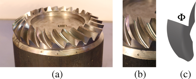
The goal is to approximate the space between two teeth of a gear Φ, recall Fig. 1, by an envelope of a general tool Ψ such that there is a bi-tangential contact between Φ and Ψ on both sides of the tooth space (double-flank machining). The unknowns in an optimization-based algorithm are both the machining tool Ψ and a ruled surface R (the motion of the tool’s axis). The ruled surface is represented as a (3 × 1)-tensor product B-spline patch
where s is the parameter in the direction of rulings and t is the time parameter of the two boundary cubic B-spline curves p(t) and q(t), for more details see [11].
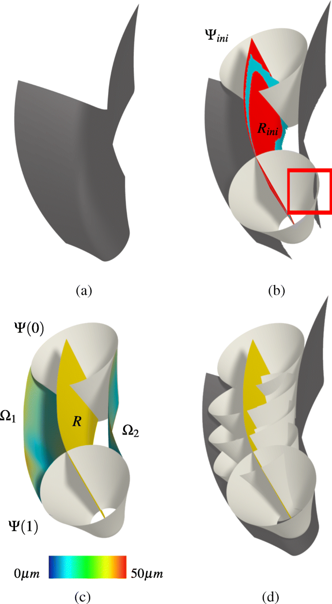
Given the valley Φ between two teeth of a gear, first the bottom part of the valley is trimmed off (as this part cannot be flank-machined anyway). This trimming operation defines two side surfaces Φ1 and Φ2. As the machining tool is aimed to have tangential contact with both Φ1 and Φ2, the bisector surface B is computed. The bisector, however, is a general surface, and therefore spline fitting method is used to compute its ruled surface approximation, see Fig. 2(b).
Design of the custom-shaped tool. (a) A cavity bewteen two teeth represented as a spline surface. (b) The self-bisector B (blue) is fitted by a ruled surface Rini (red) and an initial shape, Ψini, of the tool is computed. The initial tool and its initial position may penetrate the reference surface (framed in red). (c) The tool Ψ and its trajectory R both undergo global optimization to minimize the error of the left (Ω1) and right (Ω2) envelopes from Φ. The envelopes are color-coded by the distance error dist(Φi −Ωi), i = 1,2, that meets fine machining tolerance of 50 μm. (d) The final double-flank motion of the custom-shaped tool Ψ through the gear valley
The initial ruled surface defines the initial shape of the machining tool Ψ and its envelopes define the initial approximation of the two surfaces Φ1 and Φ2. The two (right and left) envelopes Ω1 and Ω2 are required to approximate Φ1 and Φ2, respectively, as close as possible, and within the given machining accuracy ε = 50 μm, see Fig. 2(c).
To compute the best envelopes Ω1 and Ω2, it is formulated as an optimization problem. The unknowns are the two curves p(t) and q(t) (boundaries of the rule surface R) and a scalar function d(s) that determines the sphere radius in the ruling direction s. To compute the self-bisector B of Φ, the motion of the tool is conceptualized as a two parameter family of spheres (one in time, second in the ruling direction) that should ideally touch Φ on two sides, see Fig. 2(b). B is then a locus of all such centers of spheres. The right and left sides (defined by trimming off the bottom part of the valley) surfaces Φ1 and Φ2 are used, see Fig. 2(b), to compute B, and then
where \(\mathbf {z} \in \mathbb {R}^{3}\) is the desired center of the sphere and dist is the point-surface minimal distance. The iso-surface F(z) = 0 that defines the bisector B is computed using a variant of the marching cubes algorithm, see [11] for more details.
3.2 Tool and motion optimization
In the proposed optimization-based framework, both the tool Ψ and its motion, represented by a ruled surface R, are optimized. The optimization has two main objectives: (i) to approximate the surface within a fine machining error, i.e., remove as much material as possible and (ii) to guarantee that the envelope of the tool lies inside the valley Φ, i.e., there is no overcut.
As discussed in Section 3.1, an initial ruled surface Rini is computed from the self-bisector B. This gives also, for each value of s, s ∈ [0,1], a set of scalar values that correspond to the distance dist(R(t,s),Φ) and by averaging these values for various t one obtains an initial radial functiond⋆(s). This gives an initial pair of envelopes \({\Omega }^{ini}_{1}\) and \({\Omega }^{ini}_{2}\). However, these envelopes, in general, intersect Φ which corresponds to overcutting, see Fig. 2(b).
To eliminate this phenomenon, the tool Ψini and its motion Rini both undergo global optimization. The goal is to optimize them such that \({\Omega }^{ini}_{1}\) and \({\Omega }^{ini}_{2}\) become as close as possible to Φ (remove as much material as possible) and they both lie inside the valley (no overcut). To achieve this goal, we proceed as follows. The ruled surface R is uniformly sampled both in t and s parametric directions to obtain rij := R(ti,sj), \(i=1,\dots , m\), \(j=1,\dots , n\). In our discrete approach, for each s-parameter value (fixed j), one obtains a set of discrete values dij which are the distances from Φ for a fixed point of the axis as it moves in time. To obtain a motion of Ψ that is penetration-free with Φ (no overcut), we define
where \(\underline {d}_{j}\) are the penetration-free radii. In this discrete setup, the penetration-free radius depends on the sampling density. m = 100 was set in all the experiments; this value turned out to be sufficiently large to return stable values for the valley shown in Fig. 1.
These radii are the lower bounds of the point-surface distance for each j, i.e., distances that define (discrete) radial function that corresponds to a penetration-free tool, see Fig. 2(d). Consequently, the penetration-free error is defined as
where \(d^{\star }_{j} \) are the samples of the initial radial function d⋆. Denote by d a vector of unknown distances \(\mathbf {d}:=(d_{1},\dots ,d_{n})\) and optimize both, the ruled surface R and d.
Finally, the objective that at every time instant t the tool is required to be as close as possible to Φ, but also penetration-free, is formulated. This leads to a minimization problem
subject to the axis-rigidity constraints
where dist(,) is a point-surface distance and L is the length of l. The unknowns in the minimization are the control points of the two B-spline curves p(t) and q(t), and the vector of sphere radii d. m = 100 and n = 30 was set in the numerical simulations. More details on the whole tool-optimization procedure can be found in [11].
4 Case study
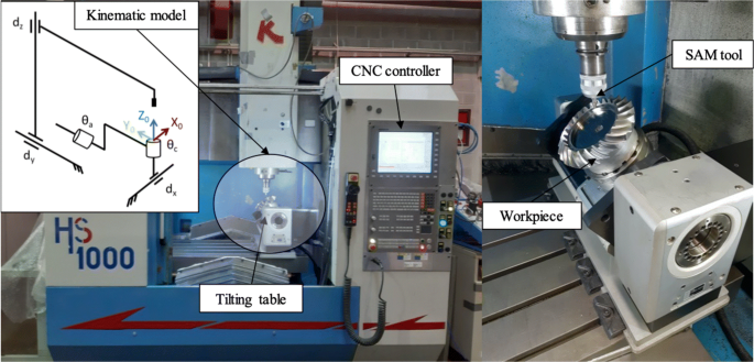
The results of the path-planning algorithm described in [11] were converted into a CL-file, and consequently converted into a G-code, and tested in a conventional machining center, Kondia HS1000, see Fig. 3. The semifinishing operations were carried out with both a ball end tool and a custom-shaped tool. The custom-shaped tool was capable of bi-tangential machining, which resulted in a simultaneous semifinishing of both walls of the tooth space. One of the objectives was to reduce machining times in the semifinishing stage as the custom-shaped tool admits wide strips of high accuracy and therefore only a single path is needed, in contrast to ball end milling which requires many milling paths.
Spiral bevel gear was selected as a case study as it is one of the most widespread components in the industrial sector. It is also the element par excellence used to transfer power from one element to another, by transmitting circular motion in terms of the gear wheel contact. One of the most important applications of gears is the transmission of movement from the shaft of a power source, such as an internal combustion engine or an electric motor, to another, end-effector, shaft. In either case, a high accuracy is highly demanded as the machining errors influence significantly the performance.
The gear wheels can be manufactured from a wide variety of materials to obtain the right mechanical properties. From the point of view of mechanical design, strength and durability, i.e., wear resistance, are the most important attributes. In general, the gear designer should consider the ability to manufacture the gear, from the formation of the gear teeth up to the final assembly of the gear in a machine. Other considerations include weight, corrosion resistance, noise, and cost. F-1550 steel (18CrMo4) was selected as the testing material for manufacturing of the spiral bevel gear, since it reaches a fairly good agreement with all the characteristics that steel needs to possess. Mechanical and physical properties and chemical composition of the used materials are shown in Table 1.
This particular spiral bevel gear was chosen, because its contact surface is larger compared to those of straight-toothed bevel gears, and this fact poses a great challenge when computing both the tool geometry and the machining path. The specific characteristics of the wheel and the theoretical mating pinion for a 5/3 gear ratio are shown in Table 2.
The tests were carried out on a conventional machining center, Kondia HS1000. This machine is a 5-axis milling machine, with 3 linear and 2 are rotary axes. The linear axes are 2 in the head (X, Z) and one in the table (Y), while both rotary axes are in the indexing table (A, C). The spindle speed capacity is 24,000 rpm.
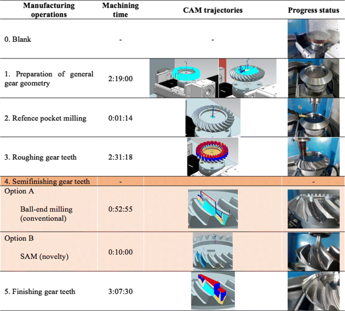
Initially a 210-mm-diameter and 120-mm-thick steel billet was used as a starting point. A series of previous operations were carried out to achieve a geometry close to the final. These operations are shown in Fig. 4 together with machining times needed for each particular machining stage.
4.1 Custom-shaped tool for SAM
Regarding the SAM tool, a custom-shaped tool was used to perform the semifinishing operation of the tooth space. Its coat was a monolayer electroplated CBN grinding with a grain size of 300 μm, see Fig. 5. A tool of this type was chosen due to its excellent tool wear characteristics, because the abrasive grains are resharpened as they break up during the machining process and also because the SAM process is well adapted to the calculation and manufacturing of a custom-shaped tool. When manufacturing the tool core, the thickness of the binding material and the abrasive grains were taken into account in order to obtain a tool with the exact geometry calculated in the modeling stage. The radius of the tool varies from 4.8 to 13.2 mm, see Fig. 6, and the thickness of the abrasive coat is 0.5 mm. Note that the tool has negative Gaussian curvature (i.e., it is not a conical tool), see [11] for more detailed analysis on the tool design.
Concerning cutting conditions, these were adapted towards the SAM technology in this sort of machining centers, in particular they were adjusted to the spindle capacities, with a spindle speed of 24,000 rpm, the limit of the machine, and a feed rate of 250 mm/min. It is important to note the effect of cutting speed on machining, especially in the context of super abrasive machining. The optimal SAM conditions of the speed of rotation should be around 60,000–90,000 revolutions [31]. However, to achieve these speeds, high performance heads are required which conventional machines do not have.
5 Results and validation
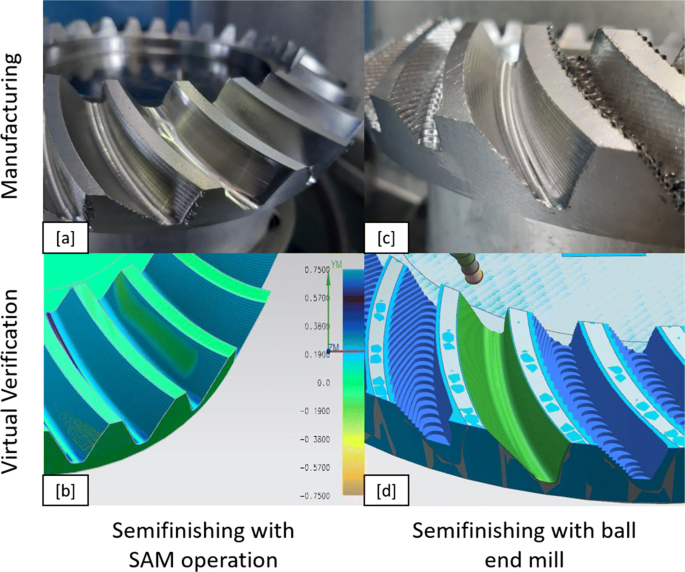
To physically validate the results of the modeling algorithm, the machining path of the custom-shaped tool in the manufacturing of a spiral bevel gear was applied. More specifically, the custom-shaped tool was used in the semifinishing operation, which is the place where Super Abrasive Machining technology has its potential niche of work. In Fig. 7, the valley between spiral bevel gear teeth is shown during roughing and semifinishing operations with milling and SAM operations. Observe a clearly visible difference in the quality of surface smoothness in Fig. 7(a) and (c).
A qualitative comparison between double-flank machining using a custom-shaped tool and ball end milling, during the semifinishing stage, is presented. Moreover, a virtual comparison against single-flank milling using a barrel tool is also made. In particular, it is shown that surface roughness and manufacturing time are significantly reduced when using double-flank machining with custom-shaped tool.
5.1 Surface roughness
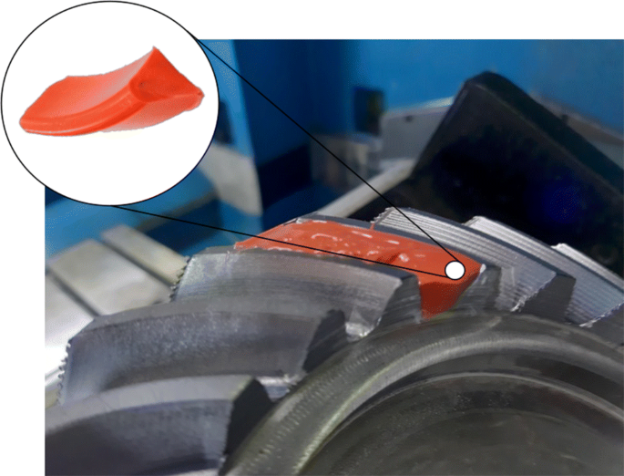
Surface roughness is one of the key parameters that influence a smooth movement between gears, their face-face contact, and consequently the life of the whole gear. Typically, the surface roughness is measured using a confocal microscope, however, due to the difficult accessibility of the faces of the gear, resin was applied in order to measure a negative of the tooth space.
The process for obtaining the negative of the face proceeds as follows: first, the area to be measured is degreased with the DN1 degreaser cleaner provided by PLASTIFORM’s own company (PLASTIFORM, Madrid, Spain). Once this is done, a closed area must be formed such that the fluid (liquid resin) covers both sides of the cavity, and then the fluid is applied to the measuring area using a dispensing gun. Finally, cca 6 min is needed for the solution to dry out, and then one can remove the negative of the cavity, see Fig. 8.
It was selected a fluid type resin, so that it could flow through the entire gear cavity and thus adapt well to the surface of the faces. Specifically, the F65 product was used, which allows a semi-flexible geometry to be obtained, suitable for measurement by both contact measuring systems and optical measurement systems. The precision obtained with this resin is ± 1 μm.
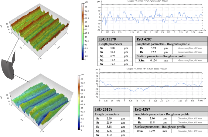
A Leica DCM 3D confocal microscope was used to analyze the surface roughness of the resin. Both sides of the cavity were analyzed, as the amount of excess of material was slightly different on each side after roughing. The adjustment of the roughness measurement in this case was a cutting length of 0.8 mm and an evaluation length of 4 mm, according to ISO 4288 [32]. Figure 9 shows the topography and related data of both sides of the cavity.
Topography on both sides of the tooth cavity shows a perfectly recognizable grinding pattern, in which there are remarked peaks and valleys along the scanned surface caused by the random distribution of the abrasive grains. It is noticeable that slightly better results in term of roughness were obtained on the right face, as the roughing operation leaves that face smoother and stepless between passes, just the opposite of the left face, as it can be seen in Fig. 7(d). However, this fact is not a limitation of the proposed double-flank approach, but it is due to the fact that the roughing stage left the right face smoother.
The results are in accordance with “indicative surface roughness comparison” that many companies handle [33]. The roughness values obtained were acceptable for a semifinishing operation because they are close to those obtained with similar strategies considering them as finishing operations.
5.2 Machining time
Another aspect that was considered in this work was the analysis of machining time during semifinishing operations on gear teeth. To this end, machining time of ball end milling operation and double-flank SAM strategy with a custom-shaped tool was measured, and barrel flank milling virtual machining time was calculated. The conventional semifinishing operation using a ball end mill with 4 mm diameter was used with a stepover of 0.33 mm of depth of cut in 3 lateral steps in each face and a feed of 2800 mm/min. On the left face, 20 axial passes were repeated 3 times axially (60 passes total) while on the right face 20 passes were sufficient. In contrast, semifinishing using a custom-shaped tool was accomplished in a single sweep with the following parameters: a feed of 500 mm/min and a spindle speed of 16000 rpm. In the case of single-flank milling using a barrel-shaped tool with 12 mm of barrel diameter, in total 20 passes were done to cover the whole surface with a feed of 848 mm/min.
With the above-mentioned values of cutting parameters for the three manufacturing semifinishing operations, the following machining time results were obtained: (i) conventional ball end milling: 2 min and 7 s, (ii) double-flank SAM semifinishing with the custom-shaped tool: 24 s, and (iii) barrel flank milling: 1 min and 8 s. Double-flank SAM dominated in terms of machining time. When comparing with the other two, in the case of ball end milling, the semifinishing machining time was reduced by 81.1%, saving in total 43 min per gear. In the case of barrel flank milling, SAM double-flank machining was 2.83 times faster than barrel flank milling. See Fig. 4 for the summary of the machining times of each particular stage.
5.3 Dimensional deviation
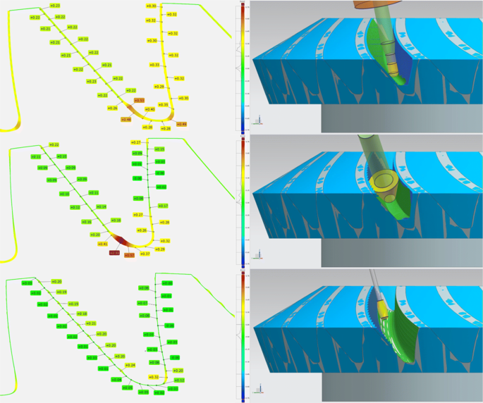
Dimensional deviation of the three tested semi-finishing strategies: ball end mill operation, double-flank SAM with a custom-shaped tool, and barrel flank milling were qualitatively compared. Figure 10 shows simulation results of the three semifinishing operations using a commercial software.
Dimensional deviation of the three virtually simulated semi-finishing strategies: Ball end mill operation (top), double-flank SAM with a custom-shaped tool (middle), and barrel flank milling (bottom). The error distribution along the tooth space (left column) and the simulated paths (right column) are shown
In the case of the root surface of the tooth, the results obtained by all methods were very similar, reaching a tooth surface excess of material of up to 0.8 mm. The results obtained on the tooth face surface show clear differences. In the case of ball finishing operation, a uniform finish was obtained along the entire surface with a stock around 0.23 mm. In the case of the SAM, there are two clearly differentiated zones. In the first zone, the right face, the values obtained in the semi-finishing are practically close to the final geometry of the piece. On the left side, an undercut of 0.1 mm was obtained along the tooth face. Comparing the above-mentioned results with barrel flank milling, it can be seen that the problem on the root surface is almost solved, except for the fillet radius, where is a stock of more than 0.3 mm. However, in the rest of the surface there is an undulation profile that goes from 0.03 mm in the bottom to 0.21 mm in the peak.
5.4 Discussion and limitations
The proposed approach significantly reduces the semifinishing time by using a properly designed custom-shaped tool. The tool has to be manufactured in advance, however, the custom-shaped tool costs are low, in particular: cylindrical steel bar F115 (85€ ) to create 4 SAM tools, i.e., 21.25€ per the steel core of the tool, and 45€ to add the abrasive grains. In total, the cost of the custom-shaped tool is 66.25€. In contrast, the on-market tool for ball end milling, VF4SVBR0200, costs 120€.
The surface roughness values range Sa = 2.59–3.87 mm using the SAM approach which is a slightly more than the numbers that can be obtained by means of conventional milling [33]. Nevertheless, these values are acceptable in the case of a workpiece which later undergoes finishing operations.
Another slight limitation is that the very bottom of the cavity is not accessible with the tool whose shape is designed to double-flank the two faces of the cavity. The bottom of the cavity has to be machined using ball end milling approach.
Comparing SAM double-flank machining with flank milling with barrel tools, both approaches offer similar accuracy, but double-flank machining is faster (factor of 2.83) due to the fact that only a single sweep of the tool is needed.
The presented results are promising, however, the double-flank methodology has been tested on one specific type of a spiral bevel gear, with parameters shown in Table 2. For gears with flat (planar) teeth, the double-flank approach is not challenging as the ideal motion boils down to a plane-plane bisector computation. The other extreme of small and even more curved reference geometry such as, e.g., pinions has not been experimented with, but can be a promising venue for future research.
6 Conclusion and future work
We have presented a new variant of 5-axis flank machining, called double-flank. In this machining methodology, not only the machining path, but also the shape of the tool itself are the unknowns in an optimization-based framework. The numerical simulations received in [11] have been validated by physical manufacturing of a steel spiral bevel gear. A custom-shaped SAM tool was designed and created for this purpose and applied in the semifinishing stage. The physical results confirmed the results obtained in the simulation stage, namely that the machining error gets reduced, the surface roughness is within a standard range, and most remarkably, the machining time of the semifinishing stage is reduced by order of magnitude when compared to ball end milling. When compared to flank milling with a barrel tool, the machining time is reduced by factor 2.83. These are very promising results towards future development of double-flank machining as a standard manufacturing technology.
As a future research we aim to further develop this methodology and focus on other geometries, e.g., blades and screw rotors, that seem to be well-suited for double-flank milling methodology using custom-shaped tools. Another research thread can go towards milling as the concept of double-flank methodology is not limited only to abrasive tools, but could also be used for cutting tools with flutes.
References
Krumme W (1967) Klingelnberg–Spiralkegdräder (Klingelnberg Spiral Bevel Gears) (in German). Springer, New York
Zhang Z, Song Y, Xu C, Guo D (2012) A novel model for undeformed nanometer chips of soft-brittle hgcdte films induced by ultrafine diamond grits. Scr Mater 67(2):197–200
Fuentes-Aznar A, Ruiz-Orzaez R., Gonzalez-Perez I. (2017) Numerical approach for determination of rough-cutting machine-tool settings for fixed-setting face-milled spiral bevel gears. Mech Mach Theory 112:22–42
Stadtfeld HJ (2014) Gleason Bevel Gear Technology: The Science of Gear Engineering and Modern Manufacturing Methods for Angular Transmissions Gleason Works
Watson HJ (2013) Modern gear production. Elsevier, New York
Deng X-Z, Li G-G, Wei B-Y, Deng J (2014) Face-milling spiral bevel gear tooth surfaces by application of 5-axis CNC machine tool. Int J Adv Manuf Technol 71(5-8):1049–1057
Álvarez Á, Calleja A, Ortega N, De Lacalle L (2018) Five-axis milling of large spiral bevel gears: toolpath definition, finishing, and shape errors. Metals 8(5):353
Suh SH, Jih WS, Hong HD, Chung DH (2001) Sculptured surface machining of spiral bevel gears with CNC milling. Int J Mach Tools Manuf 41(6):833–850
Gibson I, Rosen DW, Stucker B et al (2014) Additive manufacturing technologies, vol 17. Springer, New York
Bo P, Bartoň M (2019) On initialization of milling paths for 5-axis flank CNC machining of free-form surfaces with general milling tools. Comput Aided Geom Des 71:30–42
Bo P, González H, Calleja A, De Lacalle LNL, Bartoň M (2020) 5-axis double-flank CNC machining of spiral bevel gears via custom-shaped milling tools—part I Modeling and simulation. Precis Eng 62:204–212
Machchhar J, Plakhotnik D, Elber G (2017) Precise algebraic-based swept volumes for arbitrary free-form shaped tools towards multi-axis CNC machining verification. Comput-Aided Des
Bo P, Bartoň M, Plakhotnik D, Pottmann H (2016) Towards efficient 5-axis flank CNC machining of free-form surfaces via fitting envelopes of surfaces of revolution. Comput Aided Des 79:1–11
Li C, Bedi S, Mann S (2008) Flank millable surface design with conical and barrel tools. Comput-Aided Des Appl 5:461–470
Zhang Z, Huang S, Wang S, Wang B, Bai Q, Bi Z, Kang R, Guo D (2017) A novel approach of high-performance grinding using developed diamond wheels. Int J Adv Manuf Technol 91 (9):3315–3326
Zhang Z, Cui J, Wang B, Wang Z, Kang R, Guo D (2017) A novel approach of mechanical chemical grinding. J Alloys Compd 726:514–524
Zhang Z, Huo F, Zhang X, Guo D (2012) Fabrication and size prediction of crystalline nanoparticles of silicon induced by nanogrinding with ultrafine diamond grits. Scr Mater 67(7-8):657–660
Zhang Z, Guo D, Wang B, Kang R, Zhang B (2015) A novel approach of high speed scratching on silicon wafers at nanoscale depths of cut. Sci Rep 5(1):1–9
Zhang Z, Bo W, Kang R, Zhang B, Guo D (2015) Changes in surface layer of silicon wafers from diamond scratching. Cirp Annals 64(1):349–352
Litvin FL, Fuentes A (2004) Gear geometry and applied theory. Cambridge University Press, Cambridge
Müller H, Thomas J (2007) Face-off: face hobbing vs. face milling. Gear Solutions 5(54):49–60
Klocke F, Brumm M, Staudt J (2014) Quality and surface of gears manufactured by free form milling with standard tools. In: Proceedings of the international gear conference, Lyon, France, pp 26–28
Álvarez Á, Calleja A, Ortega N, De Lacalle L (2018) Five-axis milling of large spiral bevel gears: toolpath definition, finishing, and shape errors. Metals 8(5):353
Zhuang W, Hua L, Han X, Zheng F (2017) Design and hot forging manufacturing of non-circular spur bevel gear. Int J Mech Sci 133:129–146
Álvarez Á, Calleja A, Arizmendi M, González H, De Lacalle LL (2018) Spiral bevel gears face roughness prediction produced by CNC end milling centers. Materials 11(8):1301
Yang X-Y, Tang J-Y (2014) Research on manufacturing method of CNC plunge milling for spur face-gear. J Mater Process Technol 214(12):3013–3019
Klocke F, Brumm M, Staudt J (2014) Quality and surface of gears manufactured by free form milling with standard tools. In: Proceedings of the international gear conference, Lyon, France, pp 26–28
Wilk W, Tota J (2008) Modern technology of the turbine blades removal machining Proc. of the* 8th Int. Conf. “Advanced manufacturing Operations”, Scientific reports, pp 347–355
González HB, Calleja AO, Pereira OMN, Ortega NR, López de Lacalle LNM, Barton M (2018) Super abrasive machining of integral rotary components using grinding flank tools
Steel composition. https://virgamet.com/18hgm-18crmo4-1-7243-18cd4-708m20-15crmo4-case-hardening-steelhttps://virgamet.com/18hgm-18crmo4-1- https://virgamet.com/18hgm-18crmo4-1-7243-18cd4-708m20-15crmo4-case-hardening-steel7243-18cd4-708m20-15crmo4-case-hardening-steel
Aspinwall DK, Soo SL, Curtis DT, Mantle AL (2007) Profiled superabrasive grinding wheels for the machining of a nickel based superalloy. CIRP annals 56(1):335–338
DIN EN ISO 4288 (1996) Geometrical product specifications (gps)—surface texture: Profile method: Rules and procedures for the assessment of surface texture
Surface finish ranges and tolerances. https://www.cnccookbook.com/surface-finish-chart-symbols-measure-calculators/
Funding
Open Access funding provided thanks to the CRUE-CSIC agreement with Springer Nature. The first author has been supported by Universidad del País Vasco (predoctoral grant PIF 19/161). The second author has been partially supported by the National Natural Science Foundation of China (Grant No. 61672187 and No. 62072139). The fifths author has been partially supported by Spanish Ministry of Science, Innovation and Universities: Ramón y Cajal with reference RYC-2017-22649 and PID2019-104488RB-I00. The remaining authors were supported by the European Union’s Horizon 2020 research and innovation programme under agreement No. 862025 and by the Elkartek funding program, grant no. KK-2020/00102, and also by PDC2021-121792-100 and PID2019-109340RB-100 projects.
Author information
Authors and Affiliations
Corresponding author
Ethics declarations
Ethics approval
The authors confirm that there are no ethical issues related to this paper.
Consent for publication
If accepted, the authors give their consent to the journal to publish and further distribute the article according to the journal policies.
Conflict of interest
The authors declare no competing interests.
Additional information
Data availability
The data (the shape of the tool + its motion), as a part of European Union’s Horizon 2020 project, will be available on the project homepage.
Code availability
The source may undergo other IP issues (e.g., patenting) and will therefore not be publicly available.
Consent to participate
All the authors are aware of being co-authors and gave their consents.
Publisher’s note
Springer Nature remains neutral with regard to jurisdictional claims in published maps and institutional affiliations.
Rights and permissions
Open Access This article is licensed under a Creative Commons Attribution 4.0 International License, which permits use, sharing, adaptation, distribution and reproduction in any medium or format, as long as you give appropriate credit to the original author(s) and the source, provide a link to the Creative Commons licence, and indicate if changes were made. The images or other third party material in this article are included in the article's Creative Commons licence, unless indicated otherwise in a credit line to the material. If material is not included in the article's Creative Commons licence and your intended use is not permitted by statutory regulation or exceeds the permitted use, you will need to obtain permission directly from the copyright holder. To view a copy of this licence, visit http://creativecommons.org/licenses/by/4.0/.
About this article
Cite this article
Escudero, G.G., Bo, P., González-Barrio, H. et al. 5-axis double-flank CNC machining of spiral bevel gears via custom-shaped tools—Part II: physical validations and experiments. Int J Adv Manuf Technol 119, 1647–1658 (2022). https://doi.org/10.1007/s00170-021-08166-0
Received:
Accepted:
Published:
Issue Date:
DOI: https://doi.org/10.1007/s00170-021-08166-0


