
Abstract
With product life-cycles getting shorter and limited availability of natural resources, the paradigm shift towards the circular economy is being impulsed. In this domain, the successful adoption of remanufacturing is key. However, its associated process efficiency is to date limited given high flexibility requirements for product disassembly. With the emergence of Industry 4.0, natural human-robot interaction is expected to provide numerous benefits in terms of (re)manufacturing efficiency and cost. In this regard, vision-based and wearable-based approaches are the most extended when it comes to establishing a gesture-based interaction interface. In this work, an experimental comparison of two different movement-estimation systems—(i) position data collected from Microsoft Kinect RGB-D cameras and (ii) acceleration data collected from inertial measurement units (IMUs)—is addressed. The results point to our IMU-based proposal, OperaBLE, having recognition accuracy rates up to 8.5 times higher than these of Microsoft Kinect, which proved to be dependent on the movement’s execution plane, subject’s posture, and focal distance.
1 Introduction
During the last decades, environmental degradation and a significant increase in worldwide consumption levels have led to the ever-more scarce availability of natural resources. This is aggravated by the high pollution levels associated to both the manufacturing of new products and the lack of legislation for their disposal once their end-of-life is reached [1, 2]. Having become a growing concern for academia, industry and policymakers, a production model shift towards the circular economy (CE) is being strongly impulsed [3].
In this regard, secondary-market processes, most of which are built up onto the disassembly concept [4], are gaining momentum as a means to extending products’ useful life. Their implementation is, therefore, raising high expectations towards limiting worldwide landfill, with remanufacturing being clearly differentiated from repair, reconditioning or recycling initiatives due to higher associated quality and value-recovery rates [5].
Disassembly is key for the success of remanufacturing [6, 7]. Although it has been traditionally performed manually due to challenging flexibility requirements, autonomous disassembly operations performed by robots are highly desirable to reduce associated costs and increase efficiency. In this regard, many difficulties arise when determining the optimal disassembly sequence and obstacle-avoiding path for robots’ end-effectors [8]. Human intervention in remanufacturing is, therefore, a significant value-adding factor which reinforces the social dimension of sustainability [9].
The proliferation of Industry 4.0—built upon key-enabling technologies such as Internet of Things (IoT), augmented reality, and cloud computing [10]—has shed light on innovative human-robot interaction (HRI) communication interfaces like speech and gesture recognition. In order to achieve the most natural interface through an improved user experience, mainly two gesture-recognition approaches have been extensively studied: vision systems (commonly based on mounted camera sensors and image processing techniques to estimate body pose), and wearable approaches (body-embedded sensors monitoring accelerations). While each of them has different strengths and weaknesses in terms of accuracy, processing time, power consumption, and cost, an experimental comparison has not been yet validated in the literature to the best of our knowledge.
To fill this gap, this work addresses the experimental performance evaluation of both gesture-recognition approaches in a remanufacturing use case. Based on our wearable-based movement recognition algorithm that was recently presented [11]—the so-called Low-Frequency Movement Characterization Algorithm (LoMoCA)—a set of improvements have been carried out in order to process data from two systems in real-time: (i) the Microsoft Kinect v2 RGB-D device (hereinafter Kinect)—one of the most extended computer-vision commercial devices [12]—and (ii) our developed OperaBLE wristband, which embeds low-frequency inertial measurement units (IMUs) with a low-power microcontroller unit (MCU), and a Bluetooth low energy (BLE) communication interface [13]. By defining a set of gestures oriented to change the end-effector’s position (left, right, backward, forward shifts) as well as action-oriented gestures (clean, tool-specific, flip, right tool, left tool, and screw), different accuracy tests are performed and discussed. The contribution of this paper is, therefore, twofold: (i) Kinect communication and processing capabilities’ integration with LoMoCA algorithm for real-time robot’s remote control, and (ii) experimental comparison under different scenarios and user setups.
The remainder of this paper is structured as follows. Section 2 provides a background on remanufacturing in Industry 4.0 and state-of-the-art of HRI interfaces. Section 3 addresses the development methodology used, the software/hardware tools and the experimental setups. Section ?? includes our results and offers a brief discussion, and Section 5 highlights the main conclusions and future research directions.
2 State-of-the-art
2.1 Remanufacturing in industry 4.0
During the last decades great efforts have been made to impulse a paradigm shift towards the CE – regenerative by design [3]. In this sense, remanufacturing is finding its way through with a view to restoring products to “like-new” condition while minimizing worldwide demand of natural resources, carbon emissions and landfill, that is, closing material and information loops [14].
Remanufacturing is regarded as a key strategy towards the Triple Bottom Line dimensions of sustainability, namely (i) environmental, (ii) economic, and (iii) societal [9, 15]:
-
(i)
Remanufacturing is aimed at reducing carbon footprint and consumption of raw materials and energy—up to 85% less energy is required for the remanufacturing of a product compared to that of its manufacturing [16].
-
(ii)
Its economic benefits lie in the lower price of remanufactured products—as low as 60% compared with those that are manufactured [17].
-
(iii)
The fast growth of the remanufacturing industry has a positive impact on social welfare by leading to the creation of new job opportunities not necessarily tailored for experienced labor [18].
The barriers to remanufacturing are mostly of technical and economic nature. Unknown customer willingness to return used products causes great uncertainties regarding return rates and timings. Therefore, forecasting the required availability of raw materials or parts turns into a challenging task [19]. On top of that small batch sizes and the quality condition of returned cores call for a high level of flexibility so as to react appropriately to various product reconditioning requirements [20]. In addition, the willingness of original equipment manufacturers to remanufacture used products is typically hampered by their lower profitability in sales [5]. In this respect, governmental directives and legislation are regarded as necessary incentives supporting remanufacturing activities [2].
The success of remanufacturing is substantially determined by the disassembly process, which is referred to as an essential step in literature [6]. Despite this being traditionally performed manually, there is growing interest in robot-assisted approaches achieving a higher degree of efficiency at a lower cost [4, 21]. Disassembly sequence planning, aimed at reaching the optimal disassembly sequence, is gaining weight towards robotic disassembly [8]
With the advent of advanced digitization technologies within the fourth industrial revolution—the so-called Industry 4.0 [10]—the concept of autonomous robotics is becoming ever more feasible thanks to essential pillars like IoT, augmented reality, big data or cloud computing, among others [22, 23]. This is seen as a new fundamental paradigm shift of industrial production, which offers innumerable possibilities for the sustainable development of the remanufacturing industry [24]. While assuming the fulfillment of economic and environmental dimensions, the spotlight is increasingly being put on social sustainability and its implications [25, 26]. As a result, human-centered approaches are highly desirable in order to exploit the full potential of remote robot-assisted remanufacturing—especially when disassembly needs to be performed in hazardous environments [27].
2.2 Gesture recognition for HRI
The challenging requirements of (re)manufacturing in terms of flexibility can be clearly benefited from the adoption of cyber-physical systems (CPS), that is, the interconnection of physical-world operations with computing and communication infrastructures [28].
When it comes to establishing the interplay between humans and robots, far from relying on a direct manipulation, CPS bring a wide range of mediating user interfaces that pursue a more natural interaction according to various user-interface requirements [29]. To date, gesture recognition, speech recognition and multimodal approaches are of particular interest [30]. Gesture recognition is regarded as particularly intuitive and effective, which is typically addressed using mounted cameras—vision-based approaches—or embedded body sensors—wearable approaches.
Vision-based approaches rely on image processing and object recognition. According to the nature of camera sensors being utilized, these can be classified into three categories: (i) color-based (RGB), (ii) depth-based (D), and (iii) based on both color and depth (RGB-D).
In the literature, multidisciplinary vision-based approaches as well as HRI-oriented ones are found. Metha et al. [31] used a multi-camera motion capture system based on RGB sensors to achieve 3D pose data based on 2D data inputs. Furthermore, Kiruba et al. [32] achieved accuracy rates higher than 84% in body-pose computation by using a single RGB camera sensor. In this case, however, real-time capabilities were not guaranteed. Dong et al. [33] reduced required processing times achieving real-time operation in a HRI domain using a single RGB camera, in this case, at the expense of increasing hardware complexity and energy consumption.
Mueller et al. [34] achieved nearly real-time pose estimation and shape reconstruction of two interacting hands using infrared (IR) sensors. Based on depth sensors embedded in the commercial solution Leap Motion, Devine et al. [35] targeted the one-hand control of robotic arms to lift standard objects while Erdougan et al. [36] addressed the estimation of human intention in industrial environments.
Despite the individual use of RGB and depth (D) sensors achieving satisfactory results, several studies focus on their combined use (RGB-D systems) for improved gesture recognition. In this regard, Microsoft Kinect [12] is one of the most extended solutions as a trade-off between accuracy and affordability. Being able to detect body skeleton, this commercial device includes IR and RGB sensors to achieve an accurate pose estimation and movement capture. In the HRI domain, Mazhar et al. [37] and Arivazhagan et al. [38] achieved robust hand gesture detection using the 3D skeleton extraction feature of a Kinect device.
In general terms, vision-based approaches have received special attention in the literature due to highly accurate results, some of them even achieving a real-time operation. As a common drawback shared by all the studied solutions, computational efforts and, hence, hardware requirements tend to be particularly high. In addition, despite RGB-D approaches having overcome some of the typical computer-vision issues, some technical limitations still arise when high contrast or absence of shiny surfaces cannot be guaranteed [39, 40].
With the advent of lightweight IoT technologies and wireless body area networks [41], wearable-based approaches are increasingly being adopted as a cost-effective alternative to computer-vision systems. Motion capture devices are typically based on IMUs which have a low demand of hardware resources and energy consumption. Compared to camera sensors, IMUs provide freedom of user location and do not require a specific user orientation. As a result, different studies in the literature have explored their applicability and performance towards gesture recognition in the HRI domain.
Some studies fully rely on IMUs considering either accelerometer data (three degrees of freedom) or accelerometer and gyroscope data (six degrees of freedom). Mendes et al. [42] used three-axis accelerometers for gesture recognition and subsequent behavior classification. Similarly, but in a manufacturing context, Neto et al. [43] fed an artificial neural network with accelerometer data. Despite achieving accurate gesture classification (up to 98%) in HRI assembly-oriented scenarios, real-time requirements were not fulfilled. Chen et al. [44], conversely, provided a multimodal approach, where both depth camera data and inertial sensor data were used to study fusion characterization approaches for human action recognition. In this regard, our algorithm LoMoCA was presented [13], but a comparison with other approaches was not carried out. Therefore, as stated above, one aim of the present work is to compare the results obtained through our accelerometer-based system, providing real 3D movement data, with data provided by the Microsoft Kinect device, widely used in computer vision studies.
3 Materials and methods
This section comprehensively describes the system developed for the comparison of Kinect motion recognition and our accelerometer-based approach. In order to ensure a fair comparison, some necessary adjustments, detailed below, were performed to guarantee that the system does not influence the results and provides an unbiased movement recognition method for both approaches.
Our recognition system, presented in [11] where further detail can be found, is composed of three main parts:
-
Two wristbands, OperaBLE for sending movement data and ControlaBLE to manage the operation speed of the robot, based on LightBlue Bean hardware, which embeds an ATmega 328p MCU and CC254x Bluetooth System on Chip (SoC), connected to LSM303 accelerometer/gyroscope.
-
One processing device, called Edge Node.
-
One remote control device, called Remote Controller. Both the Edge Node and the Remote Controller consist of a Raspberry Pi 2 model B single-board computer (quad-core ARM Cortex-A7 CPU).
Figure 1 shows OperaBLE and Kinect devices with their axis system. Although in this orientation both devices share the same axis system, when OperaBLE is placed in its natural position on the wrist, a rotation of the axes around the X-axis is produced. Thus, processing is necessary, as explained in Section 3.3, in order to match the axes.

Kinect (left) and OperaBLE (right) axis system
3.1 Gesture recognition algorithm
The component around which the experiments were built is our LoMoCA algorithm. It was developed to recognize movements using a small number of samples [11]. The algorithm will not be addressed in depth in this paper. Nonetheless, a brief description is essential to understand the experiments and the subsequent results. The main aim of LoMoCA is to provide a mechanism to recognize movements with a low sampling rate. This is particularly desirable when wearables are used to save energy for extending the battery life.
The flow of data begins with the BLE link between the wristbands and the Edge Node. The data collection stage uses two bands, one is responsible for sending commands to vary the speed of execution of the movement in the robot, and the other is used to perform the movement and to send acceleration and angular velocity data to the Edge Node. This node, thanks to its asynchronous execution, is able to manage several devices at the same time without entering into a deadlocked state, which provides a protection mechanism against failure.
Our algorithm analyzes the movement performed by the operator and the processing board sends the corresponding command to the remote-control board attached to the robot, which triggers a specific operation on the robot. The controller board links each command to a given task on the robot. As a result, the performance of the robot is not dependent on the skills of the operator, which means that the task will always be performed to comply with the required quality standards. The communication between these boards is done via Message Queuing Telemetry Transport (MQTT). It is a lightweight communication protocol for IoT devices, usually over TCP/IP, based on a publish-subscribe network protocol. An MQTT broker manages topics where messages are published to resend this information to the subscribed clients. In this particular case, the broker is on the local side and it is the Edge Node which performs this task.
With regard to LoMoCA, it comprises seven main states that can be observed in Fig. 2. Some points are key to understand the results and the discussion generated. The seven states are the following:
-
(i)
Listener: waits until a new movement arrives from OperaBLE or a new pattern is being selected for comparison with the movement carried out.
-
(ii)
Movement normalization: detects the relevant acceleration axes and compares them with the normalized axes of patterns stored. This phase discards movements with different normalized axes.
-
(iii)
Discard pattern: discards the previously selected pattern as it does not correspond to the movement executed.
-
(iv)
Dynamic limit determination and DTW: the comparison processing is based on dynamic time warping (DTW) to measure the similarity of two temporal sequences (in this case movements) which can be performed at different speeds. The dynamic limit depends on the number of samples of movement and patterns being compared and it is used to set a specific limit for each case.
Fig. 2 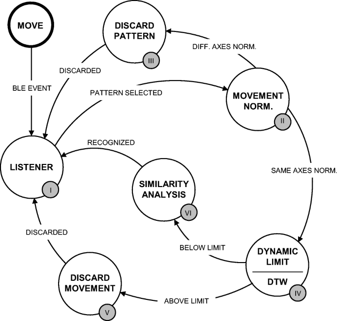
Edge Node: LoMoCA state machine
-
(v)
Discard movement: the movement does not match any pattern and it is not recognized.
-
(vi)
Similarity analysis: in case there are several candidate patterns matching the movement, it selects the most similar one.

The movements included in the experiments are split into two groups, displacement and operations.
-
The displacement movements provide robot positioning along the workspace: forward, backward, left, right. Although LoMoCA is able to recognize any type of movement, these ones were selected in order to simplify the comparison task. Moreover, our gesture recognition system and LoMoCA were tested in advance using the same movements, achieving real-time gesture recognition with a latency lower than 65 ms, a recognition accuracy above 95% in all of them, and a great user acceptance. Complex movements would imply an added processing by Kinect (e.g., track several joints to detect rotation) and the comparison could be affected by any error adapting the data. By using these simple movements, the wrist position data collected from Kinect are converted directly into accelerations and sent to the Edge Node for analysis.
-
In addition, some common operations in disassembly processes have been added to test the performance of OperaBLE. The operations comprise clean, screw, flip, right tool, left tool, tool-specific. These are further detailed in Section 3.4 where their functionality and the involved axes are specified.
3.2 System configuration and data adaptation
Kinect and OperaBLE data were collected simultaneously to process the same movement in both cases. A representation of the system developed to test both approaches is shown in Fig. 3. The left side of the figure shows the local operation of the system, where Kinect and OperaBLE data are acquired and sent to the Edge Node, via BLE and MQTT, respectively. The node processes both movements using LoMoCA and sends the corresponding command to the remote control nodes attached to the robots (on the right side). The control devices are subscribed to the MQTT topics and they are notified when a new command is ready for them.

Experimental setup (left) and remotely-controlled robot (right)
For reliable comparison of movement collection and recognition using LoMoCA, it is essential to process the Kinect data so that they are perfectly adapted to the format used by OperaBLE without interfering with the real values read. The vision-based approach retrieves position data using an RGB camera and IR sensors to calculate the depth, whereas accelerometers provide real acceleration data in all three dimensions. Therefore, wrist position data provided by Kinect has to be adapted to obtain acceleration data in order to compare both approaches.
-
–
Position to distance: as the Kinect provides positional data measuring its distance to the body detected, the first step is to obtain the distance between position samples by subtracting the current position from the previous one.
-
–
Velocity calculation: knowing the distance and the time difference between both samples, we can obtain the velocity of the wrist joint during the execution of the movement between current and previous position.
-
–
Acceleration determination: finally, the difference of two consecutive velocities is determined and divided by the time elapsed, obtaining the acceleration. Since only one velocity is obtained for every two positions, and only one acceleration for every two velocities, it was necessary to start collecting data one sample earlier and stop one sample later in order to match the movement of the Kinect with the OperaBLE one.
3.3 System data flow for simultaneous recognition
In addition, a proper management of communications between the elements involved in the system is crucial to provide reliable data. It was necessary to conceive a mechanism to inform the Kinect when the movement captured by OperaBLE started and finished. A sequence diagram has been depicted in Fig. 4 to show the flow of information in the system. The Kinect is continuously acquiring data to maintain a buffer of one sample. When the movement begins, OperaBLE sends the initial batch of data through BLE and the Edge Node publishes a start message as control command in the Kinect topic. The Kinect stores the position data until an end of movement is received. Then, position data is processed and adapted to obtain acceleration data, as commented previously. Meanwhile, the movement sent from OperaBLE is processed in the Edge Node. After the processing, Kinect sends the collected data using the same encoding as OperaBLE. Once the movement has been recognized, it is sent to the Remote Controller in both cases.

Information flows in the system: OperaBLE and Kinect movement data processing
Some additional aspects were considered to adapt the Kinect data properly:
-
Sampling frequency: given the low sampling frequency algorithm developed, a high sampling frequency could adversely affect the performance of the Kinect. Thus, the data acquired per second was adjusted to be close to the one used in OperaBLE.
-
Time-window setting: to ensure that Kinect data correspond to the complete movement of OperaBLE, the wristband sends a control message at the beginning and at the end of the movement, so that both devices are synchronized in time. Latency measurements were conducted to adjust the data interval and ensure that the same movement in both devices was analyzed.
-
Axes correspondence: the reference system and positive axes direction were adapted according to the OperaBLE ones. The procedure to obtain the acceleration sign is slightly different in Z-axis (Kinect) due to the lack of negative positions in this axis. In this case, the direction of movement determines the sign of the axis. The other axes do have negative values depending on whether they are located on one side of the Kinect or the other. In Fig. 1 can be seen that the axis system in both cases is the same. However, OperaBLE is in a different orientation in operation and the correspondence is defined as follows: −X≡ X, Z ≡ Y, −Y ≡ Z.
-
Data encoding: data in Kinect are encoded as in OperaBLE. From the Edge Node’s point of view, Kinect behaves like a wristband, sending movement data to be processed by LoMoCA.
3.4 Experimental setup
The experiments were split into two parts. First, a comparison between Kinect and OperaBLE performance was carried out under different conditions that could affect the devices. Second, the performance of OperaBLE was tested by conducting operations related to disassembly processes.
With regard to the comparison, Table 1 shows the four scenarios that were tested during the experiments using both Kinect and OperaBLE devices. Since the experiments were designed to measure the Kinect’s accuracy with respect to the OperaBLE’s, the parameters defined were only expected to vary Kinect’s characterization performance.
The setups defined are based on the focal length (straight-line distance to Kinect’s lens to the testing subject), the height of the lenses (with respect to the ground plane), the subject’s body pose (either sitting or standing), and the room’s light level, measured with the ambient light sensor LTR-329ALS-01 (range from 0.01 to 64k lux). Regarding the workspace, it is a clear room so as not to hinder the Kinect’s recognition task. Setup I, as can be noticed, was defined to optimize Kinect’s performance: optimal focal length and height (determined through experimentation), standing position, and suitable light conditions. Setup II to Setup IV varied independently each of the previous conditions (higher focal length, sitting position, and poor light conditions). A total of 160 movements, 40 times each movement, were in each setup. In all cases, the height of the lenses was set to 60 cm, since it proved to be optimal.
At first sight, it was expected that Setup II to Setup IV would perform worse than Setup I. Nevertheless, a different impact of the scenario conditions on each of the defined movements might serve to extract valuable information about Kinect’s performance.
Table 2 shows the path followed by the displacement movements: forward, backward, right, left. Only one pattern per movement was considered, since they are short movements and the number of samples and relevant axes used are few.
The remaining movements were tested using OperaBLE exclusively due to the reduced recognition rates of the Kinect with these complex movements. Table 3 shows the movements that correspond to the operations performed by the robot. Two experiments were conducted involving these movements. First, OperaBLE performance executing isolated actions, where at least 80 movements were performed both sitting and standing. Then, a sequence of movements conforming a disassembly process of an electronic device, for which 40 process repetitions were completed.
The operations selected are commonly carried out in remanufacturing processes of electronic devices, where cleaning the surface, flipping the device and screwing/unscrewing were selected to be separate movements (not included in tool-specific) due to the frequency of its use in this type of processes. Moreover, tool-specific (TS) was introduced in order to be able to perform different actions depending on the specific tool incorporated in the robot. Since a method is required to exchange the tool during the process, right tool and left tool actions were included.
4 Results and discussion
The proposed scenarios were aimed at testing common situations that may occur in a remanufacturing use case. The worker sitting down to do his/her work, not keeping the same distance from the vision system or inadequate lighting are daily situations that could affect the performance of the system. In case of accelerometer-based systems, there are also drawbacks as the impossibility of moving during the execution of the action or the excessive sensitivity that may lead to errors when colliding with elements during movement. In addition, the proposed system was to be tested as a means to evaluating its performance during the execution of movements related to remanufacturing, assembly and disassembly operations.
4.1 OperaBLE and Kinect comparison
The first scenario corresponds to the ideal conditions with the aim of obtaining optimal data. The lighting level was correct, the distance was 1.5 m, which proved to achieve the optimal recognition, and the subject’s posture was standing. A comparison of raw acceleration data captured by Kinect and OperaBLE can be observed in Fig. 5. The upper charts correspond to the data of the five movements captured by Kinect, while the lower part shows data obtained by OperaBLE in the same cases. The difference in the number of samples is caused by the adaptive data capture of Kinect, but in this case it is not relevant for the recognition because the difference is just a few samples and LoMoCA will assign a higher dynamic limit as compensation.

Comparison of raw acceleration data of successfully recognized movements in Setup I
At a first glance, there is a large difference between Z-axis values in Kinect and OperaBLE. It is due to the measurement of the gravity by the accelerometers. However, this fact does not affect the recognition because relevant axes are normalized and this difference is compensated. It is noticeable as well that OperaBLE data have a smoother shape in general. However, the shapes of X- and Z-axes in Kinect are pretty similar to the ones in OperaBLE. The problem lies in the Y -axis, which corresponds to the depth on the Kinect, and shows an erratic and changing behavior. This makes sense because the depth is the most difficult axis to be appreciated with an external device. The X-Z plane is covered correctly by the camera and IR sensor but the Y -axis has to be computed from the data captured by the IR sensor.
The operation movements are affected by the gravity in several axes during its execution. For this reason, it was not included in the following tests, since the Kinect does not sense the gravity and, therefore, the data provided for this movement will not be comparable. Despite the variability of the data in some cases, LoMoCA was able to recognize all movements.
A comparison of movement recognition accuracy data, computed as the number of successful characterizations divided by the total number of movements performed, was collected for each scenario as it is shown in Fig. 6. Under these ideal conditions, the recognition rate was between 48.65 and 55.88% except for left movement, which was 29.27%. This is caused by the inability to correctly track the wrist at some point during the execution of the movement, resulting in unexpected data that cause the movement not to be recognized.

Comparison of Kinect accuracy with respect to OperaBLE
The conditions in real environments are changing constantly. For this reason, the same experiment was carried out in a variety of scenarios. In Setup II the subject was sitting at the optimal distance. The results showed that left and right are equally detected, almost 40% of the times, but forward and backward recognition falls sharply with less than 20%. The problem here is originated by the alignment of the wrist with the Kinect, which prevents a clean view, leading to erroneous acceleration values that do not allow a correct recognition.
The Setup III is relevant to see the behavior of the system when augmenting the distance between the subject and the Kinect from 150 to 200 cm. Surprisingly, this scenario revealed the lowest accuracy results of the vision system. The accuracies of almost all movements were below 20%. The reason is that depth measurements under these conditions worsen, causing too many errors of excessive magnitude to recognize most of the movements.
Finally, Setup IV aimed to test the level of accuracy achieved by Kinect in poor lighting conditions. Due to the use of IR sensors, the results obtained were significantly better than for Setups II and III. Therefore, the Kinect is not affected to a large extent by the level of light. However, the recognition of forward movement had a low performance. This might be due to the limits imposed by Kinect to begin the recognition of new elements, contrarily to backward, which is being recognized while it moves away.
Some interesting movements are shown in Fig. 7 for the sake of appreciating errors that prevent Kinect from recognizing some movements correctly. These are two false-negative movements, where left is a clear example of how a wrong sample can cause a failure in the movement recognition. When working with a low sampling rate, it is essential that each sample is correct. High precision is not absolutely necessary, although the shape of the obtained curves should not be affected to a great extent. In this case, the X-axis is the one that is normalized, i.e., the relevant axis in this movement. As can be observed, the shape is very similar to the one obtained in OperaBLE. However, in the seventh sample, there was a one-off error that completely changed the shape of the curve, making the movement impossible to recognize. This may be due to the difficulty of detecting the wrist at every sample and a misinterpretation of the hidden points by the Kinect.

Kinect false negatives when recognizing left and forward movements in Setup I
A different reason caused the false negative in the forward movement. Here, we can see an error related to the axes that are not supposed to be relevant (X-axis and Z-axis), which were normalized due to a sample flaw in the third point in both cases. As the normalized axes do not match the pattern, the movement is not recognized as forward.
4.2 OperaBLE’s performance in disassembly operations: a remanufacturing case study
This section presents the results obtained by our solution in the performance test for each movement that corresponds to a disassembly operation. Figure 8 depicts the recognition accuracy ratio, the misrecognition of other movements, and the recognition failure. The first column of each operation shows the results obtained in standing position, while the second shows those for the seated position.

Recognition ratio of operations
As can be seen, there are no major differences between the two positions. All movements have a recognition rate above 90%, except right tool. This point will be examined in detail by means of Fig. 9, where the number of patterns saved for each movement is an important aspect: four for tool-specific, three for clean, screw and left tool, two in the case of flip, and only one for right tool. The possibility to add as many patterns as required is a great advantage of the system as it allows a better recognition of the movement, even more accentuated if the movement performed involves different relevant axes.

Acceleration and angular velocity differential factors in right tool operation (NR stands for not recognized)
However, including numerous patterns for the same movement also entails risks. This is the case of left tool. It is a relatively short movement and right tool is highly similar to it. As mentioned before, right tool has only one pattern for comparison, while for left tool 3 patterns were included. This fact provides almost perfect recognition of left tool, but it is also the cause of almost one out of two wrong recognitions (right tool being misrecognized as left tool), which only occurs in this movement.
Figure 9 shows the differential factors (DFs) of acceleration and angular velocity obtained for right tool. In this case, the dynamic limit is set at 600 for all cases, which means that a DF below the limit is a valid axis to match the pattern. Around 170 right tool operations were carried out and nine were considered to be left tool as shown by the red star markers. Furthermore, five out of nine movements should not have been recognized, as can be seen in NR markers in the graph for the y-axis of the gyroscope.
This issue is caused by the excessive number of patterns saved for left tool, which practically achieves perfection in this case, but at the expense of worsening another movement with similar characteristics. Therefore, it is necessary to include only the necessary patterns, so as not to interfere in the rest of the movements, causing an incorrect classification.
The electronic disassembly as case study was considered appropriate, since it is a common process where remanufacturing plays a significant role. In this case, the sequence of operations carried out to open, desoldering and clean an electronic device was the following: flip, unscrew, right tool, desoldering, left tool, and clean. This particular case study has been defined, but the operations included can be used in any other process related to the remanufacturing of electronic components.
A summary of the main results obtained can be found in Table 4. The range of the number of samples was from 8 in the shorter to 17 in the longer movements, implying a difference in the movement duration greater than one second.
The last column shows that 30 complete sequences were recognized, although if we remove the misrecognized ones a sequence recognition of 38/40 is obtained (there were only 3 failures—Flip, TS, and LT—and two of them were in the same sequence). As mentioned previously, the excess of patterns saved for left tool and the similarity of the movement with right tool caused that, although right tool was recognized, the system opted for left tool in the final classification. This reduced the recognition ratio from 95% to 75%, which shows that the proper determination of patterns is a decisive factor to achieve a high rate of successful recognitions.
5 Conclusions and future work
As the remanufacturing industry continues to grow, high expectations exist for robot-assisted disassembly to increase efficiency and reduce operational costs. Given the demanding requirements of disassembly operations in terms of flexibility, the human factor is key for the success of remanufacturing industries. In this domain, different human-robot interfaces exist at practice, of which gesture recognition has received special attention due to its intuitive ease of use.
This work has addressed an experimental comparison of two HRI systems: (i) a wearable-based approach (OperaBLE wristband based on three-axis acceleration data provided by IMUs) and (ii) a computer-vision approach (Kinect commercial device using an RGB camera and IR sensors). Data gathered by both systems (3D acceleration data in the case of OperaBLE, and 3D processed position data in the case of Kinect) are used as input to our low-frequency movement characterization algorithm (LoMoCA), which runs in an edge IoT node located nearby. This node, in turn, sends commands to the corresponding robot through MQTT-enabled Remote Controllers.
Having adapted both input data flows so as to be processed in real-time by LoMoCA, a performance evaluation has been conducted using OperaBLE wristbands and Kinect RGB-D cameras simultaneously. A set of conclusions are provided in the following lines:
-
(i)
The use of IMUs for movement characterization is, in general terms, compatible with lightweight MCUs using low-frequency sampling rates. Vision-based approaches, typically, require more powerful hardware resources to obtain 3D information from two-dimensional data.
-
(ii)
Wearable devices need to be powered by an external battery module, which requires a more optimized data gathering algorithm and low-power communication protocol. Vision systems, conversely, can be easily plugged in. Nevertheless, in terms of absolute consumption, OperaBLE is up to 950 times less power consuming.
-
(iii)
Despite context settings influencing the characterization accuracy for both systems—OperaBLE and Kinect—industrial scenarios are likely to have a greater impact on Kinect’s performance due to varying lighting conditions and body pose. Regarding OperaBLE, a mobile subject will impact more significantly on acceleration being used for characterization.
-
(iv)
Based on the experimental results obtained, Kinect presents a higher dependency on the plane where movements are performed. Thus, accuracies differ significantly depending on context conditions (e.g., ambient luminosity or focal length) for movements being performed in the antero-posterior axis (changes in depth).
As future work, we plan to increase the complexity and number of movements included in the system in order to detect and improve possible failures in the classification of look-alike movements, thus approaching real remanufacturing use cases. Furthermore, data fusion from different devices could be an interesting point of improvement to address a wider variety of scenarios.
References
Ramírez FJ, Castellani M, Xu W (2020) Autonomous remanufacturing. The International Journal of Advanced Manufacturing Technology. https://doi.org/10.1007/s00170-020-05559-5
Zlamparet GI, Ijomah W, Miao Y, Awasthi AK, Zeng X, Li J (2017) Remanufacturing strategies: a solution for WEEE problem. J Clean Prod 149:126–136
Geissdoerfer M, Savaget P, Bocken NM, Hultink EJ (2017) The circular economy–a new sustainability paradigm? J Clean Prod 143:757–768
Ramírez FJ, Aledo JA, Gamez JA, Pham DT (2020) Economic modelling of robotic disassembly in end-of-life product recovery for remanufacturing. Comput Indust Eng 142:106339
Matsumoto M, Yang S, Martinsen K, Kainuma Y (2016) Trends and research challenges in remanufacturing. Int J Precision Eng Manufact-Green Technol 3(1):129–142
Liu J, Zhou Z, Pham DT, Xu W, Ji C, Liu Q (2018) Robotic disassembly sequence planning using enhanced discrete bees algorithm in remanufacturing. Int J Prod Res 56(9):3134–3151
Liu C, Zhu Q, Wei F, Rao W, Liu J, Hu J, Cai W (2019) A review on remanufacturing assembly management and technology. Int J Adv Manufact Technol 105(11):4797–4808
Zhou Z, Liu J, Pham DT, Xu W, Ramirez FJ, Ji C, Liu Q (2019) Disassembly sequence planning: recent developments and future trends. Proc Instit Mechan Eng Part B: J Eng Manufact 233 (5):1450–1471
Singhal D, Tripathy S, Jena SK (2020) Remanufacturing for the circular economy: study and evaluation of critical factors. Resour Conserv Recycl 156:104681
Lasi H, Fettke P, Kemper HG, Feld T, Hoffmann M (2014) Industry 4.0. Business Inform Syst Eng 6(4):239–242
Roda-Sanchez L, Olivares T, Garrido-Hidalgo C, de la Vara JL, Fernández-Caballero A (2020) Human-robot interaction in Industry 4.0 based on an Internet of Things real-time gesture control system. Integrat Comput-Aided Eng Pre-Press(Pre-Press) 1–17
Kinect M. (2021) https://developer.microsoft.com/windows/kinect/. Accessed: 22-1-2021
Roda-Sanchez L, Garrido-Hidalgo C, Hortelano D, Olivares T, Ruiz MC (2018) OperaBLE: an IoT-based wearable to improve efficiency and smart worker care services in Industry 4.0. J Sensors 2018
Bernard S (2011) Remanufacturing. J Environ Econ Manag 62(3):337–351
Matsumoto M, Ijomah W (2013) Remanufacturing. In: Handbook of sustainable engineering. Springer Netherlands, pp 389–408
Hazen BT, Mollenkopf DA, Wang Y (2017) Remanufacturing for the circular economy: an examination of consumer switching behavior. Bus Strateg Environ 26(4):451–464
Rathore P, Kota S, Chakrabarti A (2011) Sustainability through remanufacturing in India: a case study on mobile handsets. J Clean Prod 19(15):1709–1722
Raz G, Ovchinnikov A, Blass V (2017) Economic, environmental, and social impact of remanufacturing in a competitive setting. IEEE Trans Eng Manag 64(4):476–490
Östlin J, Sundin E, Björkman M (2009) Product life-cycle implications for remanufacturing strategies. J Clean Prod 17(11):999–1009
Yang S, MR AR, Kaminski J, Pepin H (2018) Opportunities for Industry 4.0 to support remanufacturing. Appl Sci 8(7):1177
Lee CM, Woo WS, Roh YH (2017) Remanufacturing: trends and issues. Int J Precision Eng Manufact-Green Technol 4(1):113–125
Górriz JM, Ramírez J, Ortíz A, Martínez-Murcia FJ, Segovia F, Suckling J, Leming M, Zhang YD, Álvarez Sánchez JR, Bologna G, Bonomini P, Casado FE, Charte D, Charte F, Contreras R, Cuesta-Infante A, Duro RJ, Fernández-Caballero A, Fernández-Jover E, Gómez-Vilda P, Graña M., Herrera F, Iglesias R, Lekova A, de Lope J, López-Rubio E, Martínez-Tomás R, Molina-Cabello MA, Montemayor AS, Novais P, Palacios-Alonso D, Pantrigo JJ, Payne BR, De la Paz lópez F, Pinninghoff MA, Rincón M, Santos J, Thurnhofer-Hemsi K, Tsanas A, Varela R, Ferrández JM (2020) Artificial intelligence within the interplay between natural and artificial computation: advances in data science, trends and applications. Neurocomputing 410:237–270. https://doi.org/10.1016/j.neucom.2020.05.078
Kerin M, Pham DT (2020) Smart remanufacturing: a review and research framework. Journal of Manufacturing Technology Management
Garrido-Hidalgo C, Ramirez FJ, Olivares T, Roda-Sanchez L (2020) The adoption of Internet of Things in a circular supply chain framework for the recovery of WEEE: the case of lithium-ion electric vehicle battery packs. Waste Manag 103:32–44
Stock T, Seliger G (2016) Opportunities of sustainable manufacturing in Industry 4.0. Procedia Cirp 40:536–541
Garrido-Hidalgo C, Hortelano D, Roda-Sanchez L, Olivares T, Ruiz MC, Lopez V (2018) IoT heterogeneous mesh network deployment for human-in-the-loop challenges towards a social and sustainable Industry 4.0. IEEE Access 6:28417–28437
Sheridan TB (2016) Human-robot interaction: status and challenges. Hum Factors 58(4):525–532
Jazdi N (2014) Cyber physical systems in the context of Industry 4.0. In: 2014 IEEE International conference on automation, quality and testing, robotics. IEEE, pp 1–4
Gorecky D, Schmitt M, Loskyll M, Zühlke D (2014) Human-machine interaction in the Industry 4.0 era. In: 2014 12th IEEE international conference on industrial informatics. IEEE, pp 289–294
Berg J, Lu S (2020) Review of interfaces for industrial human-robot interaction. Current Robot Rep 1(2):27–34
Mehta D, Rhodin H, Casas D, Fua P, Sotnychenko O, Xu W, Theobalt C (2017) Monocular 3d human pose estimation in the wild using improved CNN supervision. In: 2017 International conference on 3d vision. IEEE, pp 506–516
Kiruba K, Shiloah ED, Sunil RRC (2019) Hexagonal volume local binary pattern (h-VLBP) with deep stacked autoencoder for human action recognition. Cogn Syst Res 58:71–93
Dong J, Xia Z, Yan W, Zhao Q (2019) Dynamic gesture recognition by directional pulse coupled neural networks for human-robot interaction in real time. J Vis Commun Image Represent 63:102583
Mueller F, Davis M, Bernard F, Sotnychenko O, Verschoor M, Otaduy MA, Casas D, Theobalt C (2019) Real-time pose and shape reconstruction of two interacting hands with a single depth camera. ACM Trans Graph 38(4):1–13
Devine S, Rafferty K, Ferguson S (2016) Real time robotic arm control using hand gestures with multiple end effectors. In: 2016 UKACC 11Th international conference on control. IEEE, pp 1–5
Erdoğan K., Durdu A, Yilmaz N (2016) Intention recognition using leap motion controller and artificial neural networks. In: 2016 International conference on control, decision and information technologies. IEEE, pp 689–693
Mazhar O, Navarro B, Ramdani S, Passama R, Cherubini A (2019) A real-time human-robot interaction framework with robust background invariant hand gesture detection. Robot Comput Integr Manuf 60:34–48
Arivazhagan S, Shebiah RN, Harini R, Swetha S (2019) Human action recognition from RGB-d data using complete local binary pattern. Cogn Syst Res 58:94–104
Tsarouchi P, Makris S, Chryssolouris G (2016) Human-robot interaction review and challenges on task planning and programming. Int J Comput Integr Manuf 29(8):916–931
Albawab T, Halim I, Ahmad N, Umar R, Mohamed M, Abullais F, Basari A, Bakar M, Saptari A (2018) Upper limb joints and motions sampling system using Kinect camera. J Adv Manufact Technol 12(2):147–158
Vera D, Costa N, Roda-Sanchez L, Olivares T, Fernández-Caballero A, Pereira A (2019) Body area networks in healthcare: a brief state of the art. Appl Sci 9(16):3248
Mendes N, Ferrer J, Vitorino J, Safeea M, Neto P (2017) Human behavior and hand gesture classification for smart human-robot interaction. Procedia Manufact 11:91–98
Neto P, Simão M, Mendes N, Safeea M (2019) Gesture-based human-robot interaction for human assistance in manufacturing. Int J Adv Manufact Technol 101(1):119–135
Chen C, Jafari R, Kehtarnavaz N (2015) UTD-MHAD: A multimodal dataset for human action recognition utilizing a depth camera and a wearable inertial sensor. In: 2015 IEEE International conference on image processing. IEEE, pp 168–172
Funding
Open Access funding provided thanks to the CRUE-CSIC agreement with Springer Nature. This work was partially supported by the Spanish Ministerio de Ciencia e Innovación (FEDER, EU funds) under RTI2018-098156-B-C52 project. This work was also partially supported by VALU3S, a European co-funded innovation project that has been granted by the ECSEL Joint Undertaking (JU) [grant number 876852]. The funding of the project comes from the Horizon 2020 research programme and participating countries. National funding is provided by Germany, including the Free States of Saxony and Thuringia, Austria, Belgium, Finland, France, Italy, the Netherlands, Slovakia, Spain, Sweden, and Turkey. This work was also partially supported by Grupos I+D funding under 2021-GRIN-31042. The publication is part of the project PCI2020-112001, funded by MCIN/AEI/10.13039/501100011033 and by the European Union “NextGenerationEU”/PRTR. Luis Roda-Sanchez is pursuing his Industrial PhD under DIN2018-010177 fellowship from Spanish Ministerio de Ciencia e Innovación. Celia Garrido-Hidalgo holds 2019-PREDUCLM-10703 fellowship from FEDER, UE at Universidad de Castilla-La Mancha.
Author information
Authors and Affiliations
Corresponding author
Ethics declarations
Ethics approval
The authors confirm that the submitted work is original and has not been published elsewhere.
Conflict of interest
The authors declare no competing interests.
Additional information
Data transparency
Will be made available upon request.
Code availability
Will be made available upon request.
Publisher’s note
Springer Nature remains neutral with regard to jurisdictional claims in published maps and institutional affiliations.
Rights and permissions
Open Access This article is licensed under a Creative Commons Attribution 4.0 International License, which permits use, sharing, adaptation, distribution and reproduction in any medium or format, as long as you give appropriate credit to the original author(s) and the source, provide a link to the Creative Commons licence, and indicate if changes were made. The images or other third party material in this article are included in the article's Creative Commons licence, unless indicated otherwise in a credit line to the material. If material is not included in the article's Creative Commons licence and your intended use is not permitted by statutory regulation or exceeds the permitted use, you will need to obtain permission directly from the copyright holder. To view a copy of this licence, visit http://creativecommons.org/licenses/by/4.0/.
About this article

Cite this article
Roda-Sanchez, L., Garrido-Hidalgo, C., García, A.S. et al. Comparison of RGB-D and IMU-based gesture recognition for human-robot interaction in remanufacturing. Int J Adv Manuf Technol 124, 3099–3111 (2023). https://doi.org/10.1007/s00170-021-08125-9
Received:
Accepted:
Published:
Issue Date:
DOI: https://doi.org/10.1007/s00170-021-08125-9