
Abstract
Persian architecture is characterised by shapes and patterns, which can be analysed through mathematical models. Beside 2D patterns, many of the traditional geometric ornaments are realised on 3D surfaces such as domes or vaults. Literature mainly addresses the 3D problem by means of a 2D scheme, which is an important and synthetic representation but is not exhaustive and lacks of clarity. This paper proposes a framework based on the integration of 2D drawings, as in the traditional approach, and a photogrammetric 3D model based on a sample of standard resolution images (tourist pictures). The framework is tested on a muqarnas, a characteristic Persian ornament, in order to study and analyse its modular design and hierarchy of elements. As a case study, the entrance iwan of the Shah Mosque in Isfahan, Iran, is considered. The result is a link between the 3D patterns and the geometry of architectural elements, which completes and overcomes their schematic 2D representation.
Introduction
The occurrence of geometric design language in traditional Persian and modern Iranian buildings reveals the very close relationship between geometry, mathematics, and Persian architecture. The concurrent evolution of these three disciplines is a demonstration of the direct impact of the progress in mathematics and geometry on the development and formation of architectural elements, ornaments, and decorations (Ebrahimi and Aliabadi 2015; Ebrahimi et al. 2014). In particular, in many Persian traditional buildings, geometry is used as a generator of architecture, in both structural elements and decorative forms and patterns (Maleki and Woodbury 2008), such as mosaics and their tiles, rasmi domes, muqarnas, yazdi-bandi, columns, etc.
For example, domes are composed of surfaces, or surfaces and ribs, that distribute loads in plane or along the ribs, using geometric elements with functional aims; at the same time, the geometric decorations of domes have a spiritual and meditative meaning, and—to quote Reza Sarhangi—‘represent the sky, heaven and what lies beyond the “seven skies”’ (Sarhangi 1999: 87). Sarhangi underlines the emotional response evoked by harmonization of decorative elements and, at the same time, the intent of artists and architects of expressing their feelings and beliefs by means of geometrical harmonization. The origin of this harmonization is the conscious use of geometric elements, arranged together by means of repetition, pattern, scale, symmetry, self-similarity, colour combination, etc.
The magnificence of Persian architecture is supported by the apparent irreproducibility of its shapes. The human eye cannot easily identified the elementary shapes or the pattern schemes of decorations: the difficulties in correctly perceiving them is supported by the complexity of patterns that, on the other hand, are mainly created from basic geometric elements. An observer can perceive the perfect design intent of the craftsmen work, but he cannot understand at a first glance the geometric rules they applied. The apparent inaccessibility of such geometric language stimulates scholars and practitioners to analyse the construction rules behind them and to reproduce their geometric models.
This paper is structured as follows. "Background" presents the research background in the analysis and reconstruction of mosaic and architectural elements, focusing on the actual state of the art of methods and techniques concerning the muqarnas. "Proposed framework" describes the framework and the tools integration. "Case study and results" deals with the mathematical analysis and reconstruction of a case study, by means of the application of the proposed framework. Finally, "Conclusions" discusses some strengths and limitations of the framework, and makes some concluding remarks.
Background
2D and 3D Pattern Design
Motifs and patterns in Persian ornaments are composed and carefully coordinated in order to create 2D or 3D decorative systems. Each element plays a well-defined role, and its form, size, colour, position, and spatial orientation are the result of a precise design intent. One of the methods used in the production of Persian patterns is modular design. Modular design is the construction of a large variety of different structures from a small set of basic elements (modules). The modules are arranged to form a tessellation; they can be directly involved in the final layout (direct tessellation) or they can be only a sub-part in a major layout (invisible substrate).
A particular type of modular design is the two-level design in which geometric patterns of two different scales are combined; a small-scale pattern either fills or outlines the compartments in a large-scale pattern as in Bonner (2003). According to Cromwell (2013a), some general principles have been identified in two-level patterns: the large-scale pattern is simple and easily recognisable; the relationship between the large- and small-scale patterns is determined by some key points in the large-scale pattern; small-scale stars are centred at the key points of the large-scale pattern; generally, congruent regions of the compartments or pathways are completed in a consistent manner or have the same filling. Cromwell (2013a) proposes a classification of modular systems for two-levels patterns that can be used to create families of geometric patterns found in Persian ornament, especially in mosaics. In the first modular system, a set of polygonal tiles is arranged to form a tessellation. They have a quite simple (regular or irregular) shape with at least one axis of symmetry, and uniform colour. The tile boundaries directly generate the decorative patterns. The second set of modular systems summarised by Cromwell consists of modules decorated with a motif, generally by composing tiles with different shapes and colours. Each module (such as a tile in the case of mosaics) shows an inner geometric decoration laid on a background region. In mosaics, according to Sarhangi (2010) and other authors, a “modularity” approach is properly a method that uses the cutting and pasting of two different coloured tiles to come up with a set of two-colour modules. Some cut-tile patterns suggest a modular approach, which is based on colour contrast and repetition by trial and error methods (Sarhangi et al. 2005) and not only on mathematical rules. The tiles are still arranged to form tessellation, but their boundaries are not shown in the finished pattern. In these decorated modular systems, only the inner geometric decoration contributes to the final pattern. Other examples of Persian modular patterns are based on a self-similarity principle or multiscale ornament (Cromwell 2013a). In self-similarity, the patterns employ the same modular system to construct both a large- and small-scale patterns. Local configurations or motifs will appear at both scales, although they may be organised in different ways at the two levels. In multiscale ornaments, they contain a hierarchy of patterns at different scales.
More generally, the previous definition of modularity given for the mosaic tiles can be generalised in a similar manner to the arrangement of elements or cells in other Persian architectural ornaments.
In several Persian architecture and decorations, the presence of star patterns, regular or not, is recurrent (Sarhangi 2010; Cromwell 2013a: 6; Maleki and Woodbury 2008: 378). A regular star pattern can be created by putting n equally-spaced points on a circle and drawing, for 0 ≤ i < n, straight lines that connecting each point γ(i) to the dth next point γ(i + d) on that circle. The resulting regular star is denoted by {n/d} where n is the number of points in a star and d the jump (or step size) (Fig. 1a). The ratio n/d is the star module or star motif that controls the angles in both the tiles and the motifs. A regular star can be used to create decorative patterns either by generating a pattern itself, or by serving as a base for other, more complex patterns. This notation is derived from the mathematical notation for star polygons, in which d is an integer, but note that d < n/2 and that {n, 1} is a convex polygon with n sides (n-gon). However, in star patterns found in Persian art and architecture, d can take on any real value in [1, n/2). Craig Kaplan generalises this construction (Kaplan 2000: 106) and, when d is not an integer, point P is computed as the intersection of line segments \(\overline{\gamma (i)\gamma (i + d)}\) and \(\overline {\gamma (i + \left[ d \right] - d)\gamma (i + [d])}\). An example of this generalization is given in Fig. 1b.

a Examples of star patterns with n = 8 points on the circle and the jump d is an integer that ranges from 1 to 3; b an example of a star with n = 8 and non-integral d
A further use of a star pattern is in the creation of domes (Maleki and Woodbury 2008: 378), where it presents 3 < d < n/2. These authors analyse and reconstruct traditional rasmi domes by identifying a selection of intersection points on a star pattern and projecting them onto a dome section taken over the chords of the dome diagram. In this way, they first obtain the dome developed into a plane net and then reconstruct it by folding the star pattern along its connecting lines. In order to fold a star pattern, they need to remove the middle section of each connecting line (Maleki and Woodbury 2008: 380–382). This leaves a non-convex central polygon that is free of lines.
Accordingly, Cromwell (2013b) underlines the fact that for large d, the regular star shows a complex cell structure in its interior, most of which is discarded in decorative applications. Typically, only the outer boundary (a 2n-sided non-convex polygon) or the outer layer of cells is kept.
All of what has just been said relative to mosaics and tessellation can be equally applied to stucco, another typical Persian ornamental technique for the decoration of dome interiors. Sarhangi (1999) states that stucco is associated with the art of tessellation, ceramics, and mirror works. An example of these combinations of stucco and tiling is the entrance portal (iwan) of the Shah Mosque, Esfahan, Iran, built by Shah Abbas the Great between 1611 and 1629. The interior semi-dome of this iwan is characterised by the presence of several three-dimensional shapes, which Sarhangi compares to “wings of a star having the centre as the centre of the dome” (Sarhangi 1999: 89). Each stucco decorative element (triangles, diamonds, stars, etc.) has some corners towards the centre, creating a point of attraction for all the other points on the dome and, moreover, for the observer. The 3D “wings of a star” are one of the most characteristic features of Persian architecture, and of Islamic art as well (Petersen 1996: 206). These stalactite-like structures are called muqarnas (Dold-Samplonius and Harmsen 2015): three-dimensional architectural decorations composed of niche-like elements arranged in tiers, often covered with glazed tiles, coloured glasses, stucco, and mirrors.
According to the fifteenth-century mathematician Ghiyath al-Din Jamshid Mas’ud al-Kashi (Dold-Samplonius 1992; Van den Hoeven and Van der Veen 2010), every niche has vertical facets and a roof (Fig. 2). Each facet intersects the adjacent one at either a right angle, or half a right angle, or their sum, or another combination of these three. The two facets can be thought of as standing on a plane parallel to the horizon. Above them is built either a flat surface not parallel to the horizon, or two surfaces, either flat or curved, that constitute their roof. Both facets together with their roof are called a cell (Fig. 2a). Adjacent cells whose bases are on the same surface parallel to the horizon comprise a tier (row of cells, Fig. 2c). Between the roofs of two adjacent cells a curved surface, called ‘intermediate element’, can be located in the form of either a triangle or two triangles (Fig. 2b).

Elements of a muqarnas: a a cell; b an intermediate element; c a part of a tier consisting of four cells and three intermediate elements
Al-Kashi noted that muqarnas designs were generated from a unit square which he specifically referred to as “module” (Özdural 2000). In particular, the measure of the base of the largest facet is called the module of the muqarnas (Van den Hoeven and Van der Veen 2010: 2).
Muqarnas and similar architectural elements (e.g., yazdi-bandi and rasmi-bandi) serve to trap the light and diffuse it with gradations (Burckhardt 2009). Light changes its original direction, makes materials brightness, and enhances architectural decorations (Habib et al. 2013). The two-dimensional plan projection of a muqarnas dome consists of a small variety of simple geometrical elements (Dold-Samplonius and Harmsen 2015; Harmsen 2006), which al-Kashi identified as squares, rhombuses, half-squares, half-rhombuses, almonds (deltoids), “jugs” (i.e., quarters of an octagon), “small bipeds” and “large bipeds”, where “biped” means the complement of an almond to a rhombus (Dold-Samplonius 1992) (Fig. 3).

Two-dimensional plan projections of muqarnas geometrical elements, after (Harmsen 2006: 14)
Moreover, a muqarnas provides a gradual transition between two levels, two sizes, and/or two shapes, and a more balanced transition between structure and surface, construction and aesthetics (Spina and Carper 2009). The dome or vault geometry presents a finite number of units that are intrinsically linked to a cohesive logic of the whole, with the most simple and figural features emerging from it. Ultimately, the dome or vault remains bound to a rather simple primitive perimeter.
Analysis and Reconstruction of 3d Geometry in Persian Ornaments: a Survey of the Literature and Research Gaps and Aims
Survey of the Literature
Focusing on 3D Persian architectural elements (and, more specifically, on muqarnas), an analysis of the literature highlights some tendencies in research that can be classified on the basis of different aims, applied techniques and tools, and methodological approaches in 3D patterns analysis.
The main goals and results detected are 2D drawings or 3D models (or, simply, point clouds), used: for both geometrical reconstruction and analysis of existing buildings or, more generally, only for graphical visualization; to reproduce the building process and/or to build a physical model of the domes/vaults with their characteristic elements; to reproduce the whole geometry of domes/vaults with all their ornamental elements or to reproduce only single modular elements; to generate new complex patterns, generally by combining existing modules or cells; to define criteria for muqarnas classification.
The main techniques and tools employed to these aims are: mathematical computation (e.g., by means of algorithms for calculation or theoretical reconstruction); conventional and digital surveying; CAD modelling (e.g., direct parametric modelling or reverse modelling based on digital surveying); and a combination of these.
Moreover, in the papers we surveyed, the methodological approaches applied in 3D patterns analysis differ in the method of investigation: they mainly be classified as graphical (based on drawings and technical schemes), analytical (based on mathematics), and empirical (based on measurements of actual shapes and geometries). However, due to the elevated geometric content of the analysis, the most of the selected papers apply an analytical approach beside the others, so a combination of methods is often proposed.
In this section, the research papers we surveyed are listed and analysed in function of the proposed classification and the aim of the present paper.
The following group papers are mainly based on graphical methods, in order to solve complex problem by means of drawings and geometrical constructions, but they often integrate analytical approaches in elements calculation.
The purpose of Yaghan (2000) is to propose new three-dimensional translations of the two-dimensional plan of a muqarnas found incised on a plaster slab, discovered in Takht-i Sulayman, Iran, and studied and analysed by Ulrich Harb. Harb proposed a three-dimensional interpretation, but this does not match the general historical context suggested by the contemporary examples of muqarnas forms, nor does it match the logic of the composition suggested by the two-dimensional plan. New three-dimensional decodings of the plan are therefore proposed, using as a starting point the 2D pattern plans, and then generating new muqarnas structures by changing the values of the basic attributes of the traditional muqarnas units (height, horizontal joint, vertical joints, curve shape). This method is proposed for later studies concerning the decoding of similar historical patterns.
One of the main characteristics of a muqarnas is the possibility to represent its 3D form as a two-dimensional outline. Silvia Harmsen (2006) investigates whether this two-dimensional projection contains all structure information of the 3D muqarnas vault. An approach based on graph theory makes it possible to include the structure information of the 3D muqarnas in the 2D outline. This is done by constructing a directed subgraph from the muqarnas design. Harmsen proposes to represent every curved side of the cells by an arrow pointing to the apex of the associated element.
In (Ebrahimi et al. 2014) a survey of different methods of yazdi-bandi drawing is proposed. All these methods aim to reconstruct 2D patterns on the basis of common steps: drawing concentric circles; placing stars on these circles; connecting the stars together. In particular, (Rasouli and Bastanfard 2010) offers a method for drawing yazdi-bandi in 2D schema based on primary rules of geometry: drawing basic shapes, drawing five-pointed stars, arranging stars, connected stars, drawing rasmi-bandi, drawing shamseh (sun disc). This method is validated by implementing a computer application for yazdi-bandi reconstruction.
A design and calculation method of muqarnas is proposed in Dadkhah et al. (2012). The theme of physical reconstruction of models introduces the theme of prefabrication of elements, made possible by their modularity, as previously analysed. A first requirement of the method is to read and understand their traditional visual language by means of drawings representing muqarnas works in plan projection. In the two-dimensional representations of the complex three-dimensional muqarnas form, elements do not overlap. The authors underline some difficulties, not in distinguishing different shapes from each other in plan projections, but in understanding which element belongs to which tier. This is not part of the information included in plan projections and it is the part of their design which needs to be decoded. To the aim of prefabrication, the whole complex has to be decomposed to specific forms with limited variety and quantity. A sequential approach, based on a sequence of geometrical steps (similar to that in Rasouli and Bastanfard 2010), leads to the deduction of components and parameters of prefabrication in both the design and the construction of muqarnas, defining the basis of their modularization. Some of these parameters correspond to predetermined elements of the projection and some are dependent on the geometric system of the whole. This enables the creation of a variety of projections out of specific and almost invariable elements, and there is a predetermined three-dimensional element per each two-dimensional element in the main two-dimensional projection.
The importance of two-dimensional pattern plan is remarked in Yaghan (2010): the complexity of muqarnas varies from one muqarnas form to another depending on the 2D pattern plan that it is created upon. A computer can be used to produce the actual form for purpose of visualizing and improving design quality. However, the author underlines the effective tediousness of the muqarnas computer drafting. The use of algorithm and programs written by the authors has the goal to create traditional and also new evolutionary forms for muqarnas.
Marcello Spina and Daniel Carper (2009) present a project of muqarnas reconstruction based on archetypes: the first step is to uncover the geometric order of muqarnas and identify its primitive tiles (least common denominator); next, these primitive tiles are classified in terms of construction logic, performance, and assembly. Many archetypal vaults are identified, and the shapes of single modules (niches, pendant stalactites, figural features, etc.) are analysed, digital modelled, reproduced by molding process and newly arranged.
The following papers are mainly based on analytical methods, focusing on the calculation of elements and the implementation of algorithms for the muqarnas mathematical reconstruction. Their authors generally use 2D drawings as starting points for their calculation.
Al-Kashi’s calculations on the muqarnas are proposed in Dold-Samplonius (1992), where 2D drawings are used as a support for computing the surface area of rows of ornamental regular concavities forming parts of roots of representative domed buildings in the Islamic world. She gives the geometric basis of the computation which is based on decomposition in standard geometric forms together with the evaluation of the area of a plane projection multiplied with an appropriate factor to account for the curvature of the vaults. The results are graphically proposed as 2D views on projection plane or, in the case of single cells or small groups of cells, they are proposed as three-dimensional (axonometric) views. In the computation of geometric form, the author uses the measure-unit of the muqarnas, the so-called ‘module’, equated to 1, facilitating calculations on the muqarnas. At the end of the computation the results are converted back into standard measures.
Yvonne Dold-Samplonius and Silvia Harmsen (2015) present the results of their three-year project “Computer Reconstruction of Muqarnas”, where they analyse muqarnas and build up a database for these constructions. At the end of the project, the computer provide a three-dimensional vault of the requested time, region, and style based on a 2D plan, by means of algorithms. The project aims to collect the existent geometries, so that in case the vault has partly collapsed in time, the computer reconstruction can support archaeologists in restoring the vault.
Moreover, a method for 3D parametric modelling of rasmi domes is proposed in Maleki and Woodbury (2008). Persian architects applied a 2D star pattern on the 3D surface of the chosen shape of the dome: a traditional rasmi dome requires the selection of intersection points on a star pattern and their projection onto a dome section taken over the chords of the rasmi dome diagram. This means that the dome is constrained by the 2D drawing and the 3D geometry. On the basis of this idea, the authors propose a goal-seeking algorithm to solve the constraints within a propagation-based parametric modelling system, using a commercial 3D CAD program. Class members are developable from a planar layout of triangles, which is, in turn, generated by a simple drawing rule. This yields a parametric structure of four parameters: the number of points n and the jump d of the star generating the dome; the radius R of the 2D circle containing the star; and the final radius r of the circle covered by the 3D dome in its plan projection. The first three parameters determine the initial planar diagram, and the last determines the configuration. The algorithm follows the listed steps: draw the 2D diagram; find the section of the dome on the connecting lines; project the points on the sections; connect the points. The output is the 3D model of the dome, based on the theoretical geometric scheme of the dome (and not based on its real geometry).
In the next group, the papers are mainly based on direct measurements for reconstructing the actual geometries of the elements. The most of them apply photogrammetric techniques. The empirical approach is appropriately combined with the other approaches according to the specific aim of each study.
Yakar et al. (2009) compare conventional surveying and digital Close Range Photogrammetry (CRP) for measuring and drawing muqarnas. As a case study, the muqarnas of a portal of Sahibata Medressah in Konya, Turkey, is proposed. The paper focuses on differences between the two techniques: on one side, the conventional surveying is based on traditional tools (e.g., meter, plumb and air level), while the second one is based on CRP. Apart from the obvious advantages of the CRP in terms of accuracy, efficiency, file storage, and file sharing possibility, the main pros are the measuring and evaluation possibility offered by the digital model, aiming to draw or model the architectural elements.
The study of the Zisa muqarnas (near Palermo, in Sicily, Italy) is proposed in Garofalo (2010). This study was preceded by a topographic survey by means of digital techniques, which was fundamental to learning about these seemingly complex structures, actually made up of simple elements. To draw the topographic survey, the author conducted an extensive study of the geometry of the muqarnas. Moreover, she underlines the improvement in our understanding of muqarnas morphology thanks to the support of a 3D virtual model, which she herself developed.
In Hassani and Rafiee (2013), the authors aim to collect documentation about Persian cultural heritage by means of a low cost image-based technique. CRP was selected to carry out the project, since it still remains the most complete, economical, portable, flexible, and widely used approach in architectural applications. The authors use an amateur digital camera for taking images for 3D model reconstruction. Moreover, image-based techniques can record textural information of the surface. As stated by the authors, the aims of this documentation are, prior to any conservational measure, detailed documentation and recording of these precious resources; since this way, not only preservation requirements of the object will be identified, but also the existing condition will be recorded for future generations. The need for rapid and appropriate documentation is further supported by the numerousness of Iran’s monuments and the high possibility of occurring natural disasters. Among the others, a further example of CRP focused on Persian geometric pattern is presented in Rahnemoonfar et al. (2003).
Research Gap
The analysis of the literature about 3D Persian architectural elements highlights the fact that patterns, even relative to 3D elements, are mainly analysed and reconstructed by means of 2D schemes. Literature focuses on 2D patterns: this approach is functional and convenient when applied to 2D patterns, because it replicates the actual shapes of the ornamental elements to study. However, although many of the traditional geometric ornaments (e.g., mosaics, stucco, etc.) are realised on 3D surfaces such as domes, in many other cases the surfaces are not planar or elementary, but are formed of a complex 3D net of shapes intersecting themselves in many manners.
Some of the studies reviewed here address the 3D problem by means of 2D schemes: a 2D scheme is an important and synthetic representation (such as the bottom view of a dome or a vault) but is not exhaustive, because it lacks of spatial information. In muqarnas plan projections, the different shapes of elements are distinguishable, but it is not possible to understand which element belongs to which tier. This information is not included in plan projections and needs to be decoded. Some authors make an attempt to include three-dimensional information in 2D drawings.
In other studies, 3D models have been developed by means of direct modelling or by digital surveying: the 3D model itself may work as a document, in a better way than a 2D scheme, which is still a useful support for 3D reconstruction and schematizing. On the other hand, a 3D model is generally time-expensive, complex to obtain, more difficult to validate on actual geometry. Moreover, if using digital surveying, the model is accurate and highly affordable, but generally has a high cost due to the need for expensive hardware tools, travel, trained personnel involved in surveying or in post-processing, and software tools.
The proposed state of the art underlines many opportunities of integration of technological tools and traditional techniques: may the original drawings developed by ancient architects support new approaches in Persian architecture reconstruction? Is it possible to integrate these drawings with other sources of information, such as images or 3D models, related to the same elements to analyse?
Many of the cited authors claim that the support of a 3D virtual model improves our understanding of the morphology of 3D patterns and their elements. However, due to distance or in the case of objects destroyed by natural causes, degradation, or deliberate damage, a surveying activity cannot be performed. Is it then possible to develop a 3D model taking into account the actual geometry of a building or an architectural element without a direct, specific surveying activity? Can already existing images and pictures represent a source of information for a successful digital reconstruction?
As an example, many photographic images made by amateurs and tourists are available on the web: is it possible to use these images of low (maybe grainy) quality for a photogrammetric reconstruction, even if not specifically developed for this technique? Can free or open source software tools successfully support this process? If this approach leads to a 3D model, will this model be accurate and workable enough to support the analysis of the 3D patterns or ornaments?
In summary, in order to overcome the highlighted limits and difficulties, is it possible to analyse complex 3D patterns, and supporting their reconstruction, by integrating the main strong points of the studies we reviewed with new approaches and innovative tools?
Research Aims
The aim of this paper is to analyse and reconstruct complex 3D patterns with the support of a framework based on the integration of 2D drawings, as in the traditional approach, and a photogrammetric 3D model developed by a sample of standard resolution images, such as tourist pictures. The output model (e.g., a point cloud) will be a virtual, textured model, showing the exact shapes and positions not only of the architectural elements, but also of all the decorative motifs on each of them. For a more accurate geometric analysis and reconstruction, this output model will be further used as a support for the ensuing CAD elaboration: by direct modelling, the final 3D model will contain elements shapes, their proportions, their relative positions, and all the planes and surfaces on which they lie.
The proposed framework aims to create a support for researchers and scholars in the architectural fields in the analysis of the ornamental 3D patterns and of the geometric rules applied by ancient architects and craftsmen.
Proposed Framework
The framework described in this section defines a procedural approach to decode a 3D pattern (from the 3D actual geometry to its analysis) and, simultaneously, to clarify the rules beneath the 3D pattern design (from the 2D drawing to the 3D geometry). According to the steps in Fig. 4, the framework employs photogrammetric technique reconstruction and CAD-based modelling, and integrates some of the strength points of the methods described in the state of the art papers.

Proposed framework for 3D pattern analysis and reconstruction
The input data can be photographs by tourists and amateurs, or collected on the Internet, without specific requirements for image quality, or frames taken from high definition videos. The images must portray the object geometry from different points of view, in order to collect spatial information. A 3D textured model is developed by photogrammetry within a free or open-source software program. In a CAD environment, the systematic graphical analysis of a 2D drawing of the plan projection of the 3D elements leads to the identification of the main geometric elements and their modular pattern in the plane XY. The 3D textured model is used as a datum point in order to univocally define the position of each element in the third dimension (Z). The 3D shapes of elements are defined by the geometric construction rules developed by ancient architects: the 3D elements are directly modelled in the CAD environment. By CAD commands, the 3D elements in each modular section can be finally repeated accordingly to the identified pattern in order to model the whole structure.
The steps of the framework are shown in Fig. 4 and outlined in what follows.
Image Selection
The images are not specifically developed for photogrammetry techniques, but have to be selected on the basis of appropriate requirements. The first requirement is about image resolution: in photogrammetry, a higher image resolution will guarantee accuracy in geometry reconstruction. Some authors, as Linder (2009); Satchet (2011), suggest a minimum image resolution of 300 dpi for photogrammetry applications, and the use of at least 5 Mpx cameras. However, to the aim of the proposed framework, the image resolution is not an important input and it can vary from very low to high. In the case of low-resolution images (e.g., lower than 100 dpi), they have to be appropriately mixed with higher resolution ones, in order to avoid a lot of noise in the reconstructed model, beyond a rough reconstruction of the shapes and edges of the elements. Mixing images with different resolution can result in a useful 3D model, with good spatial information about elements and, at the same time, good shape reconstruction of geometric elements (in particular, edges and vertices). Moreover, for a photogrammetric reconstruction, images of the object from different points of view geometry must be collected. As a general principle, every part of the object to be reconstructed should be visible on at least three photos (Linder 2009; Wang 2011). If the elements are not directly visible in at least two to three photos, a gap of information will result. That means that they will be in any case reconstructed by the software, but they will be not as accurate as the others. A rather exhaustive review of images can be obtained by means of online search engines or image archives. Images generally show more than just the object required for the reconstruction, so a pre-process operation is required, consisting of isolating the portion of image that portrays the object, with the aim of reducing the computational time in the reconstructing phase. Adjusting image contrast is a further optional operation that does not affect the 3D model quality but may improve the quality of the reconstructed texture developed by the photogrammetry software. Finally, if the reconstruction is used for commercial aims, a subsequent implicit phase is the acquisition of images copyrights.
3D Model Reconstruction
To date, several free or open source photogrammetry software are available (see, for example, https://en.wikipedia.org/wiki/Comparison_of_photogrammetry_software). The main aim of this step is to create a geometric 3D structure of the elements and not their exact model. This 3D structure mainly works as an “assembly jig” for positioning the planar elements achievable from the 2D projection drawing and for the subsequent reconstruction of the foreshortened elements. The output of this step is a 3D model, containing two kinds of information: geometrical and morphological information about elements in the cloud of points model, and their decorative patterns and motifs in the textured model. The software used should permit the 3D model to be exported in a file format compatible with a CAD modeller (e.g., in .stl file format).
Analysis of Patterns and Modularity, and the Identification of a 2D Module for the Elements Repetition
This can be achieved from an already existing 2D drawing or directly reconstructed from the 3D model, and its reproduction in the CAD environment.
If already existing, the 2D plan projection can be imported in the CAD environment as a blueprint and, by sketch commands, can be easily reproduced on a plane. The analysis of the pattern is a fundamental phase in order to avoid useless work and take advantage of its modularity. In the case of muqarnas, according to many authors (Van den Hoeven and Van der Veen 2010; Dadkhah et al. 2012), the 2D elements can be classified according to a hierarchy (see Fig. 2): primary flat elements, niche-like cells, intermediate (or connecting) elements. Only a single module need be directly drawn, as it can be easily repeated by means of CAD commands, such as mirror, circular pattern, copy, etc. In this way, the profile of all the elements of the pattern is drawn and it can be integrated in the 3D model (step 4).
If the 2D plan projection of the architectural elements is not available, the exact shapes and proportions of the 2D elements can be extracted from a bottom view projection of the 3D model of the dome. If based on a single 2D photographic image, this operation will be further complicated by perspective distortion. Conversely, a projection view of the 3D model can be used for determining exact shapes and dimensions of its elements: however, in this case, a higher resolution of input images should be provided.
As an output of this third step, in both cases, the CAD surface model of the 2D plan geometry is achieved.
Integration of the 2D Elements With the 3D Model
The basic idea of this step is the conventional reconstruction of the geometry of muqarnas and similar elements (Dadkhah et al. 2012; Maleki and Woodbury 2008), in which a 2D plan projection view (or ground plan) is integrated with the section profile of a dome or a vault. In a similar way, but in a CAD environment, the 2D sketch of the pattern and the 3D model should be horizontally aligned (in a plane XY) with common reference points, such as the planar elements. Due to pattern modularity, each 2D primary flat elements of the identified module is offset in the Z direction to its final positions, i.e., the corresponding plane of the 3D virtual model. This 3D model works as a “jig”, useful for positioning the 2D elements during their assembly. This operation has a hierarchical order: the first elements to be positioned are the primary (flat) elements. Once these are fixed in their positions, some curves corresponding to the “third dimension” of the intermediate elements can be directly drawn on the 3D model. These elements, generally undetectable in 2D pictures (Van den Hoeven and Van der Veen 2010), can be modelled on the base of the primary flat elements vertices and on the curves as surface elements. Once all the elements of a module are modelled, it can be repeated as necessary in order to obtain the full geometry of the dome/vault. The output of this fourth step is a 3D surface model in a CAD format.
The frameworks aims to create a correlation between the 2D muqarnas design, or ground plan, and the 3D muqarnas structure.
Case Study and Results
The proposed framework is applied to the analysis and reconstruction of the muqarnas of the entrance portal (iwan) of the Shah Mosque (also known as the Imam Mosque) in Isfahan (Iran), built by Shah Abbas the Great between 1611 and 1629. This is a work of stucco that has been combined with the art of tiling (Sarhangi 1999; Dadkhah et al. 2012).
The plan of the iwan is rectangular and is covered by a semi-dome. According to other similar architecture (Sarhangi 1999), the transition from the semi-dome above (external structure) to the building below (interior design) is achieved by the use of 3D shapes that form a sort of star pattern, whose centre is the semi-dome centre. These 3D shapes are formed by a large number of regular stars with four, five and seven points, and some regular eight-pointed stars and irregular concave polygons, laid on planes parallel to the ground. Each star is connected to the others by means of 3D elements, creating small pointed niches, called cells, and other intermediate elements. A row of adjacent cells, having their base on the same level, parallel to the horizon, is called tier.
It would seem that the architects intended for all the stars laid on the same tier to have the same shape and the same dimensions, but—in fact—we can note differences between them. As an example, the most of the five-pointed stars are regular and they can be geometrically denominated as {5/1,6} following (Kaplan 2000: 106). However, some of them result irregular in order to fill the gaps among their adjacent tiles that form the muqarnas, so we could correctly refer to them as ‘irregular five-pointed stars that approximate the regular {5/1,6}’. Anyway, to avoid redundancy, we will use only the geometrical notation. In what follows, the application of the proposed framework is investigated and its results are presented.
-
(1)
The first step of the framework is image selection. In the case of the Shah Mosque iwan, 27 images were selected for photogrammetric reconstruction. Most of the images are selected from amateur websites and tourist reportages. Their resolution are from 72 and 350 dpi (Fig. 5). The images show the muqarnas and its elements from different points of view (Fig. 6).
Fig. 5 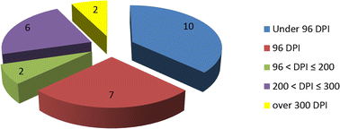
Resolutions of the selected images
Fig. 6 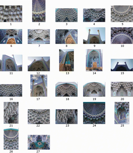
Selected images for the 3D photogrammetry reconstruction
Some of the images have to be appropriately pre-processed, by cutting out elements not pertaining to the reconstruction, as in Fig. 7.
Fig. 7 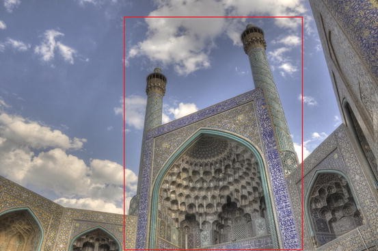
Example of image pre-processing: the red rectangle delimits the elements to be reconstructed, while all the external ones will be cut out. Original photo: Babak Farrokhi, reproduced by permission https://commons.wikimedia.org/wiki/File:Shah_mosque_isfahan.jpg (colour figure online)
-
(2)
In this work, a free application from Autodesk, called 123D Catch, was selected for its flexibility and efficiency. This software, based on photogrammetry, works by uploading all the images in a cloud-based environment and then returning a 3D point cloud textured model. The textured model allows a detailed analysis of its elements, by zooming, rotating, measuring elements distance, etc. Moreover, as in other photogrammetry software, it links the final model with each image used for its reconstruction (Figs. 8, 9), but only the elements shown in more than two to three images are created.
Fig. 8 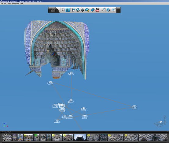
Iwan of the Shah Mosque, Isfanah: textured model of the muqarnas
Fig. 9 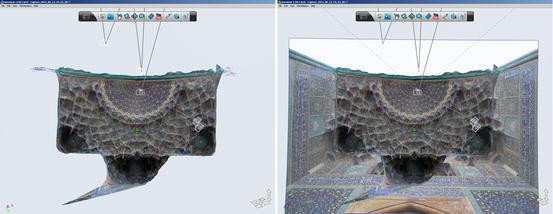
Bottom views of the textured model of the muqarnas: image contextualization
123D Catch was mainly developed for developing Rapid Prototyping models, so the output is in.obj file format. However, using another free application by Autodesk, called MeshMixer, the file can be rapidly exported in the most common neutral file format (e.g., .stl file format). In Figs. 10 and 11, two photogrammetric models are compared. They differ in the requirements for the selection of photographic images: the model in Fig. 10 is achieved only from low-resolution images (lower than 100 dpi) and a reduced number of views for each element, while the model in Fig. 11 fully respected the listed requirements. The figures show the .stl model of the muqarnas: only the second model is suitable for the subsequent reconstruction phase.
Fig. 10 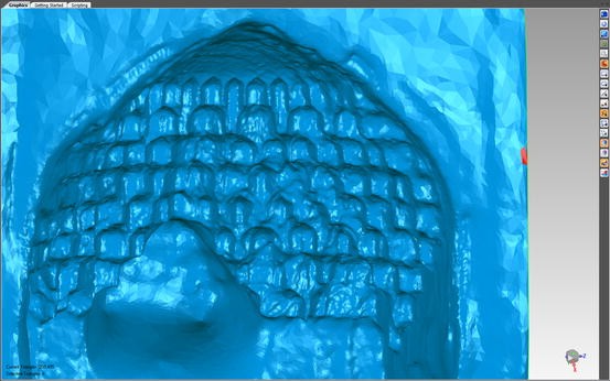
Model achieved only from low-resolution images (lower than 100 dpi)
Fig. 11 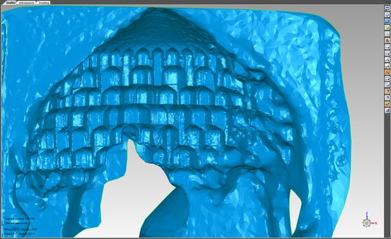
Model achieved by integrating low- and medium-resolution images (up to 350 dpi)
-
(3)
Starting from the 2D plan projection of the muqarnas of the Shah Mosque iwan, the third step is the analysis of its modularity, along radial and orbital directions. Elements and modules in the design of a muqarnas are interlocked on a two-dimensional plane without any overlaps.
The 2D plan projection used in the following analysis is drawn according to other references (Van den Hoeven and Van der Veen 2010: 9; Spina and Carper 2009: 9), but is completely revised by means of a bottom view of the 3D model.
At a first glance, the entire semi-dome can be seen as half of an irregular eight-winged star (Fig. 12), where the most external stalactite-likes elements, ending with four-pointed regular stars (in the intersection points between the red circular arcs and the red radial axes drawn in red in Fig. 13), act as the vertices of each wing. Each side sector sweeps a 22.5° angle (1/4 of a right angle), while the central sector sweeps a 67.5° angle (3/4 of a right angle). The centre of the semi-dome corresponds to the eight-winged star centre.
Fig. 12 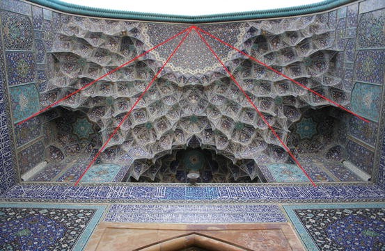
Irregular star-shaped geometry of the muqarnas. Original photo: Patrick Ringgenberg, reproduced by permission
Fig. 13 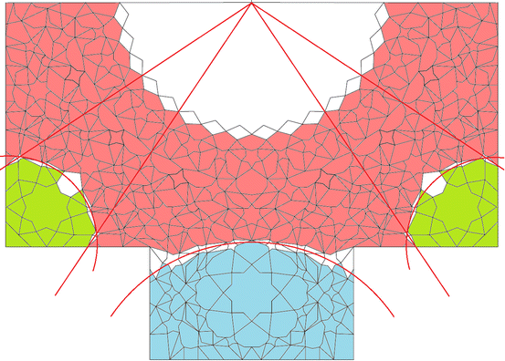
Different sub-structures in the whole muqarnas structure: in light red the primary muqarnas, in light blue the central secondary muqarnas, and in green the two symmetrical lateral secondary muqarnas (colour figure online)
Moreover, this half eight-winged star highlights four different sub-structures in the whole muqarnas structure of the iwan. In Fig. 13, the main region shown in light red corresponds to the primary muqarnas, while other three minor sub-structures (secondary muqarnas) are defined by the wings of the star itself (depicted as red circular arcs in Fig. 13). Outside of the rectangular plan of the iwan, a recessed central niche contains a secondary muqarnas (in light blue in Fig. 13); the plan of this recessed niche is rectangular. In the lower left corner of the iwan plan, and symmetrically in the right one, two further small secondary muqarnas ornaments are built (in green in Fig. 13). They are positioned in the niches between each pair of the wings of the main star-shaped semi-dome.
The elements belonging both to the primary muqarnas and the secondary ones are shown in white in Fig. 13: they correspond to the red circular arcs and subdivide the muqarnas into the described sub-structures.


However, a more systematic geometric analysis of the 3D pattern is desirable and, following (Dadkhah et al. 2012: 134–135), the following sub-steps are proposed.
-
(1)
The identification of radial axes helps identify the basic module: radial axes start from the centre of the semi-dome and pass through the centre of each primary planar element (generally stars) aligned on these axes. We see that four axes subdivide the area in four equally spaced angular sectors (45°), three complete sectors, and two semi-sectors at each external side. The central sector presents a different pattern than the two that flank it, which are identical (Fig. 14a). Each sector can be symmetrically subdivided by a second set of radial axes, originating eight equally spaced angular semi-sectors (22.5°) (Fig. 14b). Again, with a third set of radial axes, a final number of sixteen quarter-sectors (11.25°) is achieved (Fig. 14c). A quarter-sector can be considered the smallest angular module for the 3D pattern reconstruction, as described in the next points. The sixteen subdivisions correspond to the number of the sides of the central semi-rosette.
Fig. 14 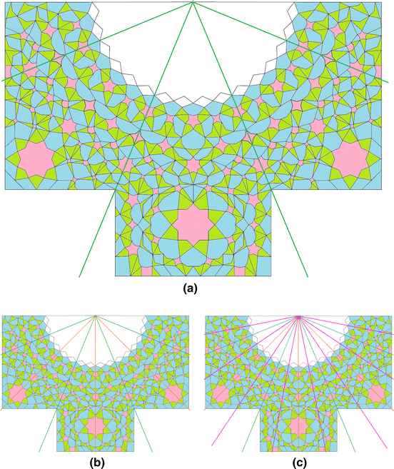
Angular sectors subdivision of the muqarnas
It is interesting to note that each angular module is mirrored from the adjacent ones in the first tier, but presents some differences as the distance from the semi-dome centre increases. This requires further analysis, as in the next step.
-
(2)
Along each radial axis, it is possible to identify some orbital axes (semi-circular axes) corresponding to different tiers. While it is not possible to identify the tiers in the 2D projection, with the help of the 3D virtual model, by rotating and zooming on primary elements, it is possible to identify the levels they lie on (Fig. 15), forming an overall number of eight tiers, corresponding to an equal number of planes (Fig. 16). All these planes are equally spaced, as reconstructed in the 3D model: the height of each niche is a constant parameter for the muqarnas.
Fig. 15 
Identification of the base plane of the upper tier
Fig. 16 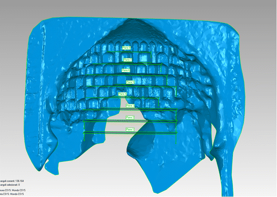
Base planes of all eight tiers
In the 2D plan projection, the centre of each flat geometric element (generally a regular star) lies on a semi-orbital axis. Each semicircle, shown in a black dashed-dotted line in Fig. 17, is laid on one of the previously identified planes. The flat elements are shown in light red; the cells in light blue, and the intermediate elements in green.
Fig. 17 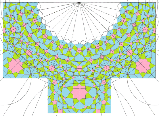
Construction of orbital axes of the mugarnas in the CAD environment, shown in black dashed-dotted lines
The first tier corresponds to the lower flat elements of the semi-dome, corresponding to the elements further from the centre. As a consequence, the eighth tier corresponds to the upper flat elements, nearest to the semi-dome rosette.
-
(3)
The identification of flat elements, called takht in Van den Hoeven and Van der Veen (2010: 134), in each tier aids the construction of cells and intermediate elements. The flat elements, also defined as primary elements or primary cells (Spina and Carper 2009), are generally located at the intersections of radial and orbital axes: these elements act as focal points in the plan projection. The surface of each flat element is modelled in the CAD environment: Figs. 18 and 19 show the correspondence between each tier and the flat primary elements in the primary and the secondary muqarnas. The complete muqarnas will be analysed in two steps, first describing the primary muqarnas and then the secondary ones.
Fig. 18 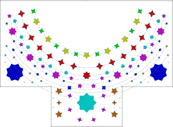
Flat primary elements and tiers: each colour corresponds to a different level. The circular arcs shown in dashed-dotted line highlight the pattern reconstruction of the primary muqarnas
Fig. 19 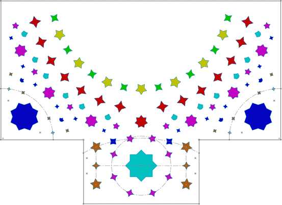
Flat primary elements and tiers: each colour corresponds to a different level. The circular arcs and the segments in dashed-dotted line highlight the pattern reconstruction of the secondary muqarnas ornaments
Because the first part of the analysis focuses on the primary muqarnas, only the flat elements laid on the circular arcs shown in Fig. 18 are considered.
On the first tier, the flat elements are {4/1.4} regular stars (in grey in Fig. 18). Each of these four stars correspond to the lower vertex of the “wings” of the semi-dome star and, therefore, they are not equally spaced in the plane. These {4/1.4} stars are symmetrical with respect to the main radial axis of both the two lateral sectors, but they are not present in the main central sector. Moreover, in the intersections between the semi-dome rectangular plan and the recessed central niche rectangular plan, two symmetrical points (shown as grey asterisks in Fig. 18) forms the base “step” (or step 0) of the arch bounding the semi-dome and the central niche itself. Each point is located along one of the main radial axes (in green in Fig. 14) and therefore it acts as a focal point in the plan projection of the other flat elements.
On the second tier, another set of eight {4/1.4} regular stars is proposed (in brown in Fig. 18). One of their two main diagonals has a radial direction. As in the previous case, they are symmetrical with respect to the main radial axis of both the two flanking sectors, but they are not present in the main central sector. However, in the arch bounding the semi-dome and the recessed central niche, two symmetrical {5/1.6} regular stars are laid on the same plane, constituting the first step of the boundary arch itself.
The third tier presents two rows of flat elements (in blue in Fig. 18) in the symmetrical lateral sectors: firstly, a leaf-shaped concave octagon is placed in the intersection of the third orbital axis and the radial axis corresponding to each wing of the semi-dome. Their total number is four elements. Again, on the fourth orbital axe, two {4/1.4} stars are symmetrically placed with respect to each leaf-shaped concave octagon. The total number of these {4/1.4} stars is twelve. On the same tier, in the arch bounding the semi-dome and the recessed central niche, two symmetrical {4/1.4} regular stars constitute another step in the boundary arch.
On the fourth tier, an almost regular pattern of alternate stars is highlighted (in violet in Fig. 18). Six {7/2} stars are placed in the intersection point of the fifth orbital axis with each of the principal radial axes, with a step of 22.5°, while eight {5/1.6} regular stars (but, in fact, some of them result irregular) are placed on the same orbital axe, but equally shifted to 11.25° with respect to the first ones. On the same tier, in the arch bounding the semi-dome and the recessed central niche, two symmetrical {5/1.6} regular stars constitute the last step in the boundary arch. The pattern of the {7/2} stars is regular except for the star on the vertical axis of symmetry of the semi-dome: this star has the same dimensions, but is laid on the sixth tier, it is radially placed nearest to the semi-dome centre and is, moreover, rotated 180°.
The fifth tier contains twelve leaf-shaped concave octagons (in light blue in Fig. 18), forming a double-spaced pattern, apart for the two central quarter-sectors (see the next tier).
The sixth tier contains fourteen {4/1.4} regular stars (in red in Fig. 18), forming an equally-spaced pattern, except for the two central quarter sectors where only the previously mentioned rotated {7/2} star (see fourth tier description) is allocated.
The seventh tier allocates eight {4/1.4} regular stars (in green in Fig. 18), forming the bases of the main stalactite-like elements. In contrast to the others, this pattern of flat elements is regular, so the {4/1.4} regular star is repeated in all the quarter-sectors.
The last tier allocates seven {5/1.6} regular stars (in yellow in Fig. 18), equally spaced on the eighth orbital axis, coincident with the previous one. For the niches below, the external vertices of these stars corresponds to the top point of the roofs of each niche. At the same time, the plane containing these stars corresponds to the virtual projection plane on which the bases of the upper row of niches lie.
As previously noted in point 1, a semi-rosette forms the central part of the semi-dome. The circular semi-rosette pattern is based on a half {32/6} star. The circumscribed semicircle is therefore divided in 16 parts, corresponding to the sides of the stars. Moreover, the sixteen subdivisions correspond to the number of the radial axes previously developed. Each sector sweeps an angle of 11.25°. In the rosette, the complex interior structure due to the star construction is discarded, so the non-convex central polygon is free of intersection lines.
The second part of the analysis of the iwan muqarnas focuses on the secondary muqarnas sub-structures and only the flat elements laid on the lines and the circular arcs shown in Fig. 19 are considered.
The main secondary muqarnas structure is built in a niche (Fig. 19) positioned in the back of the rectangular plan of the main semi-dome, and rearward from the front vertical wall. This niche is symmetrical positioned with respect to the vertical axis of symmetry of the main semi-dome. Its roof element is an {8/2} regular star, formed of two squares rotated 45°. The plane on which the {8/2} star lies corresponds to the base plane of the fifth tier of the main semi-dome. Globally, this muqarnas is arranged on four tiers, aligned to the first four tiers, as previously numbered, of the main semi-dome.
The first tier does not allocate flat elements, but contains the two symmetrical points (shown as grey asterisks in Fig. 19) previously described, in the intersections between the rectangular plan of the semi-dome and that of the recessed central niche. They form the base “step” (or step 0) of the bounding arch. Moreover, four symmetrically-located points (shown as further grey asterisks in Fig. 19) form the bases of four thin stalactite-like elements, representing the edges between the facets of cells and intermediate elements whose bases are on the same plane. These are shown in Fig. 20, where all the flat elements, cells, and intermediate elements of the whole muqarnas are shown in different colours on the basis of the tier they belong to. For example, all the elements having their bases on the first plane—and that constitute the first tier—are shown in grey.
Fig. 20 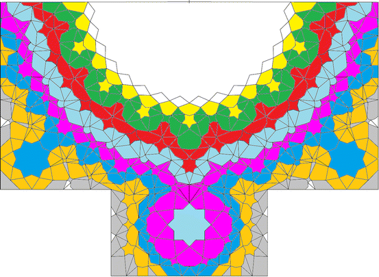
The element belonging to the same tier (i.e., whose bases are on the same plane that forms the tier) are represented with the same colour. The white elements in circular pattern correspond to the rosette; the few white elements along the perimeter are intermediate elements positioned below the first tier (colour figure online)
The second tier allocates four symmetrical {5/1.6} regular stars and two symmetrical {4/1.4} regular stars (in brown in Fig. 19), aligned on two lines running parallel to the vertical axis of the entire semi-dome. The upper {5/1.6} regular stars constitute the first step of the boundary arch cells.
The third tier allocates only the two symmetrical {4/1.4} regular stars (in blue in Fig. 19) that constitute the second step in the boundary arch.
The fourth tier is characterised by eight stars (in violet in Fig. 19) radially positioned around the {8/2} regular star of the roof: the upper two stars are the two symmetrical {5/1.6} regular stars that constitute the last step in the boundary arch; the other six are {4/1.4} regular stars.
The fifth tier contains only the {8/2} regular star: except for its front vertex, all the other vertices correspond to the top points of a row of seven large cells (see Figs. 17 and 20).
The other two secondary muqarnas structures are symmetrically positioned in the niches in the lower corner of the projection plan of the semi dome. Their roof element is an {8/2} regular star, shaped by two squares rotated 45°, with the same dimensions of the {8/2} star in the recessed niche. The plane on which these stars lie corresponds to the base plane of the third tier of the main semi-dome. Globally, these lateral secondary muqarnas are arranged on three tiers, aligned to the first three tiers, as previously numbered, of the main semi-dome.
The first and the second tier of each lateral secondary muqarnas consist of four {4/1.4} regular stars (shown in grey and brown in Fig. 19 and previously described in the primary muqarnas analysis): even if they lie on different tiers, in the plan projection they are placed in a circular pattern nonconcentric with each {8/2} regular star of the roof.
In the third tier, except for two vertices nearest to the whole semi-dome centre, all the other six vertices of each {8/2} star of the roof correspond to the top points of a row of six cells, whose bases are aligned to the second tier of the semi-dome of the main muqarnas (see Figs. 17, 20).
-
(4)
The fourth step is the integration of the 2D elements with the 3D model in the CAD environment. The 2D elements are first modelled as surfaces on a base plane and then must be offset to their real position on the muqarnas .stl model (Fig. 21). This surface model is therefore imported with the .stl file of the muqarnas in a common modelling environment. The alignment between the two models is based on the coincidence of the base planes, using common reference points, such as at least three planar elements. Each surface element (i.e., each 2D reconstructed flat element) is offset in the Z direction to its final position, corresponding to the base plane of each tier.
Fig. 21 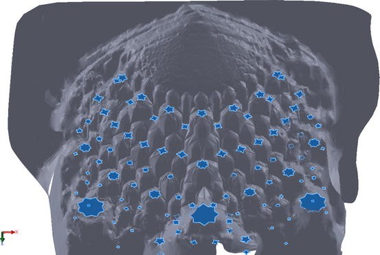
Offset of the 2D elements to their real position on the muqarnas 3D model
The identification of a radially symmetric modular structure of the muqarnas allows us to simplify the 3D reconstruction: only the elements belonging to the module will be placed and modelled, and then repeated by means of the circular pattern CAD command. The module repetition will be appropriately modified where the radial symmetry of the pattern is interrupted. After fixing the primary elements in their positions, the reconstruction proceeds hierarchically. The plan projection of the cells consists of an arrangement of rhombuses and irregular polygons, on the basis of the vertices of the primary elements, while the plan projections of the intermediate elements are mainly “almonds” and “bipeds”, according to al-Kashi’s definitions.
On the 3D model, the curves corresponding to the “third dimension” (Z direction) of cells and intermediate elements are geometrically constructed according to al-Kashi’s calculations (Dold-Samplonius 1992: 221–222; Van den Hoeven and Van der Veen 2010: 3). As previously remarked, all the cells and intermediate elements are constructed according to the same unit of measure (called the module) and the tiers are equally spaced. Similarly, in order for them to fit together, the curve on the side of each cell has to be the same.
Figure 22 describes the curve construction.
Fig. 22 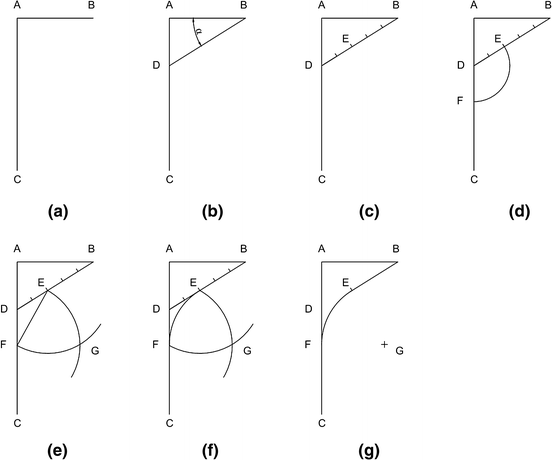
Geometric construction of the curve on cell side: a the curve is constructed within a rectangle whose height AC is twice its width AB; b the angle between the upper line AB and an oblique line BD is fixed; c the oblique line BD is divided into five equal parts; d a length of two-fifths of BD (corresponding to DE) is rotated down to the vertical line, intersecting it in F; e point G is defined as the intersection between a circle of radius EF whose centre is in E and a circle of radius EF whose centre is in F; f the arc tangent to BD (in E) and to AC (in F) has its centre in G and radius GE; g the curve consists of the segment CF, the tangent arc FE and the oblique segment EB
With the support of the 3D model, the curve is constructed in the CAD environment (Fig. 23a, b) according to the geometric construction previously described. In the most of cells of the 3D model, the angle measured between the upper line and the oblique line is 32°, very close to the theoretical value (30°) described by al-Kashi. Then, the complete surfaces constituting the cells can be modelled (Fig. 23c–f) both on the basis of the surface elements vertices and of the developed curves.
Fig. 23 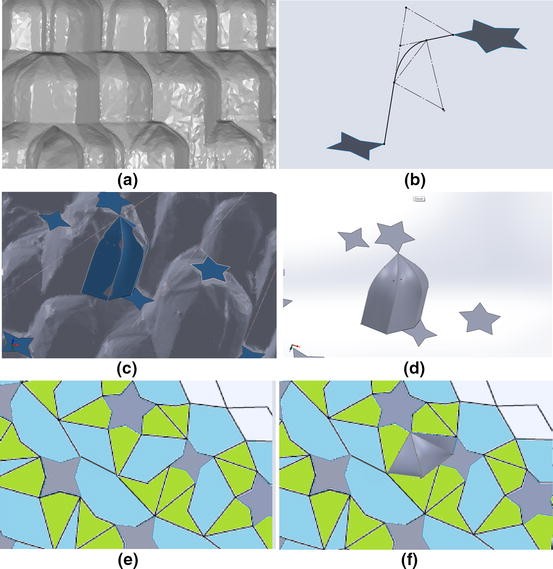
Modelling of a curve (a–b) and of a niche element (c–f)
Once all the elements of a module are modelled, it can be repeated as necessary in order to obtain the full geometry of the dome/vault. The output of this fourth step is a surface model, in a CAD format.


Conclusions
In conclusion it is interesting to remark the proposed integration of traditional design techniques with modern tools. The original drawings developed by ancient architects, or their corresponding re-elaboration, are capable of supporting new approaches to the reconstruction of Persian architecture. This attests to the high-level and significant technical and geometric contents of the building design by the ancient architects or craftsmen.
A further necessary remark is about the aim of the framework: due to its simplified approach, it cannot be compared to high-level and expensive specific tools (such as 3D scanner laser), which may offer greater accuracy in the results, but also require elevated resources (people, time, tools, etc.). However, due to its applicability and reproducibility, the proposed framework aims to create a user-friendly and smart support for researchers and scholars in the architectural fields in the analysis of the 3D ornamental patterns.
Some limitations on the proposed method mainly concern the availability of pertinent images and 2D drawings. Apart from the requirements for image quality, discussed earlier, the images have to portray all the elements from different points of view, and many buildings and ornaments have not been adequately photographed. The availability of 2D drawings, from literature or other sources, may represents another problems. However, in those cases, the proposed framework also works in the reverse direction: starting from a 3D photogrammetry model, it is possible to obtain the 2D drawing of the geometrical pattern. Starting from the plan projection of the main flat elements, all the elements boundaries can be easily detected and drawn.
As a final remark, the proposed framework may support an “a posteriori” reconstruction of architectural elements or building not subjected to specific survey, as in the case of objects destroyed by natural causes, degradation, or deliberate damage, representing a further source of documentation.
Photo credits
The author is happy to credit the following sources for the images in Fig. 6: 1, 2, 3) http://www.iranreview.org/content/Documents/Imam_Mosque.htm; 4) Author: Massimiliano Grassi, reproduced by permission https://www.flickr.com/photos/maxgrassi/14374991764/; 5) Author: Yoko Komine, reproduced by permission https://www.flickr.com/photos/oceanbaby/489534895/; 6) Author: Tilo Driessen, reproduced by permission https://www.flickr.com/photos/morelcreamsauce/535799346/; 7) Author: Nick Taylor https://www.flickr.com/photos/44124412397@N01/2456071153 licensing as in: https://creativecommons.org/licenses/by/2.0/; 8) Author: Gayle Dickson, reproduced by permission https://www.flickr.com/photos/thesloths/13664170605/in/photostream/; 9) https://commons.wikimedia.org/File:Moschee-isfahan.jpg Licensing as in: Creative Commons Attribution-Share Alike 2.5 Generic; 10) Author: Horizon https://www.flickr.com/photos/horizon/165217247/in/photostream/ licensing as in: https://creativecommons.org/licenses/by-nc-nd/2.0/; 11) Author: Sheeda Jasmine Watson, reproduced by permission https://www.flickr.com/photos/sheeda-jas/3183180818/; 12) Author: Alan Davey https://www.flickr.com/photos/adavey/4945869031/ licensing as in: https://creativecommons.org/licenses/by/2.0/; 13) Author: Alan Davey https://www.flickr.com/photos/adavey/4946593824/ licensing as in: https://creativecommons.org/licenses/by/2.0/; 14) Author: Madeleine Kynaston https://www.flickr.com/photos/madellinabird/14904065128 licensing as in: https://creativecommons.org/licenses/by-nc-sa/2.0/; 15, 16) Author: Grace McGeachin, reproduced by permission from: https://gracetheglobe.wordpress.com/2013/11/25/the-imam-mosque-of-isfahan-iran/; 17) Author: Babak Farrokhi, detail from: https://commons.wikimedia.org/wiki/File:hah_mosque_isfahan.jpg licensing as in: https://creativecommons.org/licenses/by/2.0/deed.en; 18) https://commons.wikimedia.org/wiki/File:Sally_Port_of_Sheikh_Lotf_Allah_Mosque.JPG licensing as in: GNU Free Documentation License; 19) Author: Patrick Ringgenberg https://en.wikipedia.org/wiki/Muqarnas#/media/File:Isfahan_Royal_Mosque_entrance.JPG licensing as in: http://creativecommons.org/licenses/by-sa/3.0/; 20, 21, 22, 23) Author: Patrick Ringgenberg, reproduced by permission; 24) Author: Shayan Ghiaseddin, reproduced by permission http://shayanlens.tumblr.com/post/70085820234/patterns-in-shah-mosque-iso-100-f63-1160s-55mm; 25, 26, 27) Author: Shayan Ghiaseddin, reproduced by permission https://shayanlens.wordpress.com/2015/11/30/reprocess-shah-mosque/
References
Bonner, Jay. 2003. Three traditions of self-similarity in fourteenth and fifteenth century Islamic geometric ornament. Pp. 1-12 in: Mathematical connections in art, music and science, Proceedings ISAMA/bridges (University of Granada, 2003), R. Sarhangi and N. Friedman, eds. http://archive.bridgesmathart.org/2003/bridges2003-1.pdf (accessed 23 October 2015).
Burckhardt, Titus. 2009. Art of Islam: Language and Meaning (L’art de l’islam: Langage et signification). Foreword by S. H. Nasr; introduction by J. L. Michon. English language edition (Commemorative Edition). Indiana: World Wisdom, Inc.
Cromwell, Peter R. 2013a. Modularity and Hierarchy in Persian Geometric Ornament. Preprint: 1-46. http://www.liv.ac.uk/≃spmr02/islamic/cromwell_persian.pdf (accessed 23 October 2015).
Cromwell, Peter R. 2013b. On irregular stars in Islamic geometric patterns. Preprint: 1-33. http://www.liv.ac.uk/≃spmr02/islamic/cromwell_irregular_stars.pdf (accessed 23 October 2015).
Dadkhah, Negin, Hadi Safaeipour, and Gholamhossein Memarian. 2012. Traditional Complex Modularity in Islamic and Persian Architecture: Interpretations in Muqarnas and Patkâné Crafts, Focusing on their Prefabricated Essence. In: Proceedings of 2012 ACSA FALL CONFERENCE—Offsite: Theory And Practice Of Architectural Production (Temple University, Philadelphia, PA, 27–29 September 2012).
Dold-Samplonius, Yvonne. 1992. Practical Arabic Mathematics: Measuring the Muqarnas by al-Kashi. Centaurus 35: 193–242.
Dold-Samplonius, Yvonne and Silvia Harmsen. 2015. Muqarnas: Construction and Reconstruction. In: Architecture and Mathematics from Antiquity to the Future, vol. I, pp. 709–719. Kim Williams and Michael J. Ostwald, eds. Cham: Springer.
Ebrahimi, Ahad Nejad, Morteza Aliabadi, and Soulmaz Aghaei. 2014. Dome’s Internal Decorative Elements in Persian Architecture, Case Study: Yazdi-Bandi. International Journal of Sustainable Tropical Design Research and Practice 6 (2): 113–127.
Ebrahimi, Ahad Nejad and Morteza Aliabadi. 2015. The Role of Mathematics and Geometry in Formation of Persian Architecture. Asian Culture and History 7 (1): 220–239.
Garofalo, Vincenza. 2010. A Methodology for Studying Muqarnas: The Extant Examples in Palermo. In: Muqarnas vol. XXVII: An Annual on the Visual Culture of the Islamic World, 357–406.
Habib, Farah, Fariba Alborzi, and Iraj Etessam. 2013. Light Processing in Iranian Houses; Manifestation of Meanings and Concepts. International Journal of Architecture and Urban Development 3 (3): 11–20.
Harmsen, Silvia. 2006. Algorithmic Computer Reconstructions of Stalactite Vaults—Muqarnas—in Islamic Architecture. Ph.D. Thesis, Heidelberg. http://archiv.ub.uni-heidelberg.de/volltextserver/7047/1/diss.pdf (accessed 23 October 2015).
Hassani, Fereshteh and Meysam Rafiee. 2013. An Experience in Cultural Heritage Documentation in Iran Using a Low-Cost Technique. In: ISPRS—International Archives of the Photogrammetry, Remote Sensing and Spatial Information Sciences, vol. XL-5/W2, pp. 313–318.
Kaplan, Craig S. 2000. Computer generated Islamic star patterns. Pp. 105–112 in: The 2000 Bridges Conference, R. Sarhangi, ed. Southwestern College, Kansas. http://archive.bridgesmathart.org/2000/bridges2000-105.pdf (accessed 23 October 2015).
Linder, Wilfried. 2009. Digital Photogrammetry: A Practical Course. Berlin/Heidelberg: Springer-Verlag.
Maleki, Maryam M. and Robert F. Woodbury. 2008. Reinterpreting Rasmi Domes with Geometric Constraints: A Case of Goal-seeking in Parametric Systems. International Journal of Architectural Computing 6 (4): 375–395.
Özdural, Alpay. 2000. Mathematics and Arts: Connections between Theory and Practice in the Medieval Islamic World. Historia Mathematica 27: 171–201.
Petersen, Andrew. 1996. Dictionary of Islamic Architecture. London and New York: Routledge.
Rahnemoonfar, Maryam, Mehrdad Hejazi, and Ali Azizi. 2003. Close Range Photogrammetry of Persian Architecture Patterns. In: Proceedings of the 6th International Conference of Civil Engineering, (University of Technology, Isfahan, Iran, May 2003).
Rasouli, Peyman and Azam Bastanfard. 2010. A new approach on 2D Yazdibandi in Islamic geometry. Pp. V2-344–V2-349 in: Proceedings of the 2nd International Conference on Software Technology and Engineering (ICSTE 2010, San Juan, PR, USA, 03–05 October 2010).
Sarhangi, Reza. 1999. The Sky Within: Mathematical Aesthetics of Persian Dome Interior. Nexus Network Journal 1: 87–97.
Sarhangi, Reza. 2010. Making Modules For Mosaic Designs. Symmetry: Culture and Science 21 (4): 381–392.
Sarhangi, Reza, Slavik Jablan, and Radmila Sazdanovic. 2005. Modularity in Medieval Persian Mosaics: Textual, Empirical, Analytical, and Theoretical Considerations. Visual Mathematics 25. https://eudml.org/doc/257052 (accessed 23 October 2015).
Satchet, Mourtadha Sarhan. 2011. Feasibility Study of Using Mobile Phone Camera in Digital Close Range Photogrammetry. Journal of Thi-Qar University 1 (7): 61–70.
Spina, Marcello and Daniel Carper. 2009. Tessellated Manifold. Advanced Digital Fabrication Studio. Washington University, St. Louis. http://www.frombo.com/Images/Marcelo/Tessellated%20Manifolds%20Book%20PDF_s.pdf (accessed 23 October 2015).
Van den Hoeven, Saskia and Maartje Van der Veen. 2010. Muqarnas Mathematics in Islamic Arts. Seminar Mathematics in Islamic Arts 2010, Utrecht University. http://www.jphogendijk.nl/projects/muqarnas2010.pdf (accessed 23 October 2015).
Wang, Yuan-Fang. 2011. A Comparison Study of Five 3D Modeling Systems Based on the SfM Principles, Visualsize Inc. http://www.visualsize.com/tutorial/VS_TR.pdf (accessed 23 October 2015).
Yaghan, Mohammad A. 2010. The evolution of architectural forms through computer visualisation: muqarnas example. In: The proceedings of the 2010 international conference on Electronic Visualisation and the Arts (EVA 2010, London), 113–120. British Computer Society Swinton, UK.
Yaghan, Mohammad A. 2000. Decoding the Two-Dimensional Pattern Found at Takht-i Sulayman into Three-Dimensional Muqarnas Form. Iran 38: 77–95. Published by: British Institute of Persian Studies.
Yakar, Murat, Haci Murat Yilmaz, Saadet Armagan Gulec, and Mustafa Korumaz. 2009. Advantage of Digital Close Range Photogrammetry in Drawing of Muqarnas in Architecture. Information Technology Journal 8: 202–207.
Author information
Authors and Affiliations
Corresponding author
About this article

Cite this article
Gherardini, F., Leali, F. A Framework for 3D Pattern Analysis and Reconstruction of Persian Architectural Elements. Nexus Netw J 18, 133–167 (2016). https://doi.org/10.1007/s00004-015-0287-z
Published:
Issue Date:
DOI: https://doi.org/10.1007/s00004-015-0287-z