
Abstract
Fundamental electrical laws and the associated methods of analysis, which have been discussed in the previous chapters, need tedious mathematical manipulation. These cumbersome mathematical analyses can be simplified by using advanced techniques known as network or circuit theorems. These include linearity property, superposition theorem, Thevenin’s theorem, Norton’s theorem and maximum power transfer theorem. Here, most of these theorems will be discussed with independent and dependent sources. In addition, PSpice simulation will also be used in some cases to verify the analytical results.
Access this chapter
Tax calculation will be finalised at checkout
Purchases are for personal use only
Author information
Authors and Affiliations
Corresponding author
Exercise Problems
Exercise Problems
-
4.1
An electrical circuit is shown in Fig. 4.77. Assume \(I_{p} = 1\,{\text{A}}.\) By using the linearity property find the actual value of \(I_{p}\).
Fig. 4.77 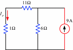
Circuit for Exercise Problem 4.1
-
4.2
Figure 4.78 shows an electrical circuit with the source voltage assigned to V s = 16 V. Calculate the actual value of \(I_{0}\).
Fig. 4.78 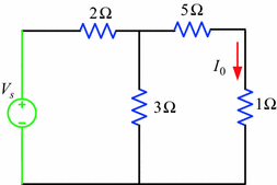
Circuit for Exercise Problem 4.2
-
4.3
Use linearity property to calculate the actual value of the voltage \(V_{0}\) of the circuit in Fig. 4.79. Assume \(V_{0} = 1\,{\text{V}}\).
Fig. 4.79 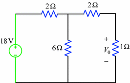
Circuit for Exercise Problem 4.3
-
4.4
Using superposition theorem determine the current in the \(4\,{\Omega}\) resistor of the circuit in Fig. 4.80. Compare the result by PSpice simulation.
Fig. 4.80 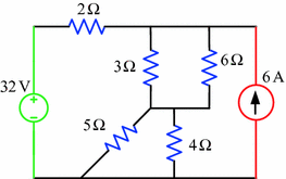
Circuit for Exercise Problem 4.4
-
4.5
Using superposition theorem calculate the current in the \(6\,{\Omega}\) resistor of the circuit in Fig. 4.81. Compare the result by PSpice simulation.
Fig. 4.81 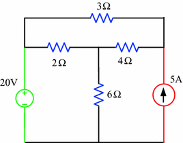
Circuit for Exercise Problem 4.5
-
4.6
Using superposition theorem find the current in the \(6\,{\Omega}\) resistor of the circuit in Fig. 4.82. Verify the result by PSpice simulation.
Fig. 4.82 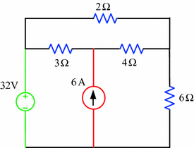
Circuit for Exercise Problem 4.6
-
4.7
Using superposition theorem calculate the current in the \(3\,{\Omega}\) resistor of the circuit in Fig. 4.83. Verify the result by PSpice simulation.
Fig. 4.83 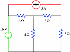
Circuit for Exercise Problem 4.7
-
4.8
Use superposition theorem to calculate the current in the \(4\,{\Omega}\) resistor of the circuit in Fig. 4.84. Verify the result by PSpice simulation.
Fig. 4.84 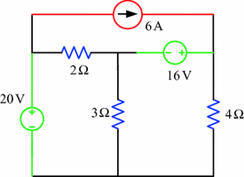
Circuit for Exercise Problem 4.8
-
4.9
Using superposition theorem calculate the current in the \(2\,{\Omega}\) resistor of the circuit in Fig. 4.85. Verify the result by PSpice simulation.
Fig. 4.85 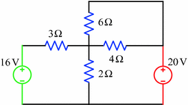
Circuit for Exercise Problem 4.9
-
4.10
Using superposition theorem determine the current in the \(4\,{\Omega}\) resistor of the circuit in Fig. 4.86. Verify the result by PSpice simulation.
Fig. 4.86 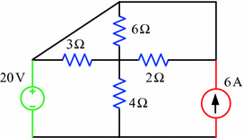
Circuit for Exercise Problem 4.10
-
4.11
Using superposition theorem find the current in the \(8\,{\Omega}\) resistor of the circuit in Fig. 4.87. Verify the result by PSpice simulation.
Fig. 4.87 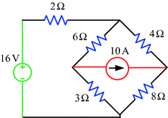
Circuit for Exercise Problem 4.11
-
4.12
Using superposition theorem find the current in the \(4\,{\Omega}\) resistor of the circuit in Fig. 4.88. Verify the result by PSpice simulation.
Fig. 4.88 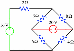
Circuit for Exercise Problem 4.12
-
4.13
Using superposition theorem determine the current in the \(6\,{\Omega}\) resistor of the circuit in Fig. 4.89. Verify the result by PSpice simulation.
Fig. 4.89 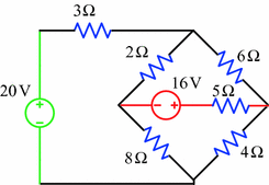
Circuit for Exercise Problem 4.13
-
4.14
Use superposition theorem to calculate the current in the \(3\,{\Omega}\) resistor of the circuit in Fig. 4.90. Verify the result by PSpice simulation.
Fig. 4.90 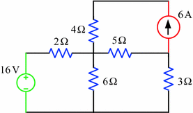
Circuit for Exercise Problem 4.14
-
4.15
Using superposition theorem determine the current in the \(5\,{\Omega}\) resistor of the circuit in Fig. 4.91. Verify the result by PSpice simulation.
Fig. 4.91 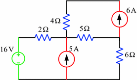
Circuit for Exercise Problem 4.15
-
4.16
Using superposition theorem find the current in the \(1\,{\Omega}\) resistor of the circuit in Fig. 4.92. Verify the result by PSpice simulation.
Fig. 4.92 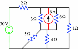
Circuit for Exercise Problem 4.16
-
4.17
Using superposition theorem calculate the current in the \(8\,{\Omega}\) resistor of the circuit in Fig. 4.93. Verify the result by PSpice simulation.
Fig. 4.93 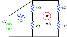
Circuit for Exercise Problem 4.17
-
4.18
Using superposition theorem determine the current in the \(5\,{\Omega}\) resistor of the circuit in Fig. 4.94. Verify the result by PSpice simulation.
Fig. 4.94 
Circuit for Exercise Problem 4.18
-
4.19
Use superposition theorem to determine the current in the \(3\,{\Omega}\) resistor of the circuit in Fig. 4.95. Verify the result by PSpice simulation.
Fig. 4.95 
Circuit for Exercise Problem 4.19
-
4.20
Using superposition theorem calculate the through the \(4\,{\Omega}\) resistor of the circuit in Fig. 4.96 and verify the result by PSpice simulation.
Fig. 4.96 
Circuit for Exercise Problem 4.20
-
4.21
Figure 4.97 shows an electrical circuit. Use superposition theorem to calculate the current in the \(6\,{\Omega}\) resistor and verify the result by PSpice simulation.
Fig. 4.97 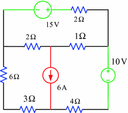
Circuit for Exercise Problem 4.21
-
4.22
Using superposition theorem determine the current in the \(5\,{\Omega}\) resistor of the circuit in Fig. 4.98. Verify the result by PSpice simulation.
Fig. 4.98 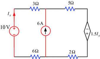
Circuit for Exercise Problem 4.22
-
4.23
Using superposition theorem calculate the voltage across the \(12\,{\Omega}\) resistor of the circuit in Fig. 4.99. Verify the result by PSpice simulation.
Fig. 4.99 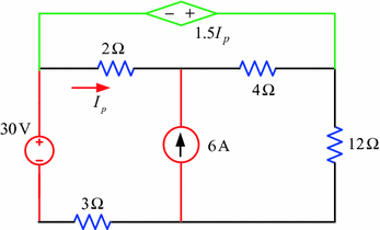
Circuit for Exercise Problem 4.23
-
4.24
Using superposition theorem find the voltage across the \(4\,{\Omega}\) resistor of the circuit in Fig. 4.100. Verify the result by PSpice simulation.
Fig. 4.100 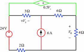
Circuit for Exercise Problem 4.24
-
4.25
Using superposition theorem calculate the voltage across the \(6\,{\Omega}\) resistor of the circuit in Fig. 4.101. Verify the result by PSpice simulation.
Fig. 4.101 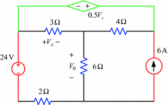
Circuit for Exercise Problem 4.25
-
4.26
Using superposition theorem find the voltage across the \(3\,{\Omega}\) resistor of the circuit in Fig. 4.102. Verify the result by PSpice simulation.
Fig. 4.102 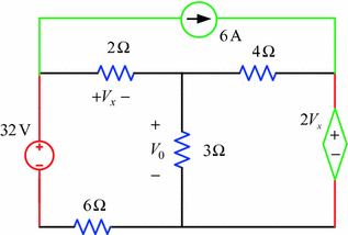
Circuit for Exercise Problem 4.26
-
4.27
Using Thevenin’s theorem find the current in the \(5\,{\Omega}\) resistor of the circuit in Fig. 4.103. Verify the result by PSpice simulation.
Fig. 4.103 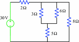
Circuit for Exercise Problem 4.27
-
4.28
Use Thevenin’s theorem to determine the current in the \(6\,{\Omega}\) resistor of the circuit in Fig. 4.104. Verify the result by PSpice simulation.
Fig. 4.104 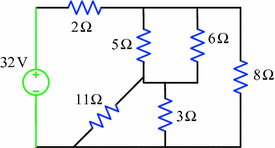
Circuit for Exercise Problem 4.28
-
4.29
Using Thevenin’s theorem find the current in the \(4\,{\Omega}\) resistor of the circuit in Fig. 4.105. Verify the result by PSpice simulation.
Fig. 4.105 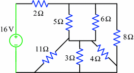
Circuit for Exercise Problem 4.29
-
4.30
Use Thevenin’s theorem to determine the current in the \(3\,{\Omega}\) resistor of the circuit in Fig. 4.106. Verify the result by PSpice simulation.
Fig. 4.106 
Circuit for Exercise Problem 4.30
-
4.31
Using Thevenin’s theorem calculate the current in the \(8\,{\Omega}\) resistor of the circuit in Fig. 4.107. Verify the result by PSpice simulation.
Fig. 4.107 
Circuit for Exercise Problem 4.31
-
4.32
Using Thevenin’s theorem determine the current in the \(10\,{\Omega}\) resistor of the circuit in Fig. 4.108. Verify the result by PSpice simulation.
Fig. 4.108 
Circuit for Exercise Problem 4.32
-
4.33
Use Thevenin’s theorem to find the current in the \(6\,{\Omega}\) resistor of the circuit in Fig. 4.109. Verify the result by PSpice simulation.
Fig. 4.109 
Circuit for Exercise Problem 4.33
-
4.34
Using Thevenin’s theorem calculate the current in the \(5\,{\Omega}\) resistor of the circuit in Fig. 4.110. Verify the result by PSpice simulation.
Fig. 4.110 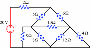
Circuit for Exercise Problem 4.34
-
4.35
Use Thevenin’s theorem to find the current in the \(10\,{\Omega}\) resistor of the circuit in Fig. 4.111. Verify the result by PSpice simulation.
Fig. 4.111 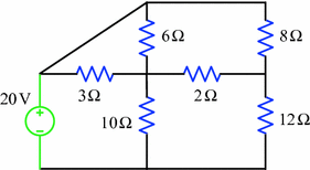
Circuit for Exercise Problem 4.35
-
4.36
Using Thevenin’s theorem determine the current in the \(12\,{\Omega}\) resistor of the circuit in Fig. 4.112. Verify the result by PSpice simulation.
Fig. 4.112 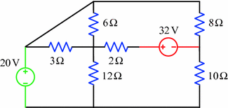
Circuit for Exercise Problem 4.36
-
4.37
Use Thevenin’s theorem to determine the current in the \(6\,{\Omega}\) resistor of the circuit in Fig. 4.113. Verify the result by PSpice simulation.
Fig. 4.113 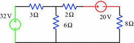
Circuit for Exercise Problem 4.37
-
4.38
Using Thevenin’s theorem calculate the voltage across the \(5\,{\Omega}\) resistor of the circuit in Fig. 4.114. Verify the result by PSpice simulation.
Fig. 4.114 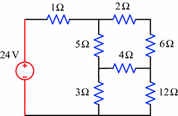
Circuit for Exercise Problem 4.38
-
4.39
Use Thevenin’s theorem to determine the current in the \(2\,{\Omega}\) resistor of the circuit in Fig. 4.115. Verify the result by PSpice simulation.
Fig. 4.115 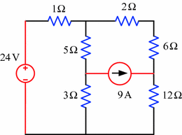
Circuit for Exercise Problem 4.39
-
4.40
Using Thevenin’s theorem calculate the power absorbed by the \(5\,{\Omega}\) resistor of the circuit in Fig. 4.116. Also, find the current by PSpice simulation.
Fig. 4.116 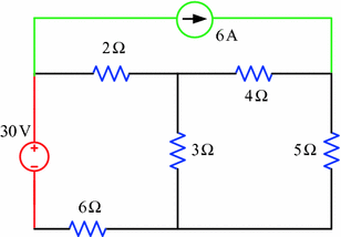
Circuit for Exercise Problem 4.40
-
4.41
Using Thevenin’s theorem determine the voltage across the \(3\,{\Omega}\) resistor of the circuit in Fig. 4.117. Verify the result by PSpice simulation.
Fig. 4.117 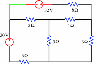
Circuit for Exercise Problem 4.41
-
4.42
Use Thevenin’s theorem to find the current in the \(11\,{\Omega}\) resistor of the circuit in Fig. 4.118. Verify the result by PSpice simulation.
Fig. 4.118 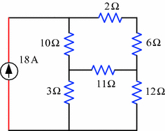
Circuit for Exercise Problem 4.42
-
4.43
Using Thevenin’s theorem determine the current in the \(8\,{\Omega}\) resistor of the circuit in Fig. 4.119. Verify the result by PSpice simulation.
Fig. 4.119 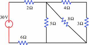
Circuit for Exercise Problem 4.43
-
4.44
Using Thevenin’s theorem find the current in the \(4\,{\Omega}\) resistor of the circuit in Fig. 4.120. Verify the result by PSpice simulation.
Fig. 4.120 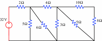
Circuit for Exercise Problem 4.44
-
4.45
Use Thevenin’s theorem to determine the current in the \(3\,{\Omega}\) resistor of the circuit in Fig. 4.121. Verify the result by PSpice simulation.
Fig. 4.121 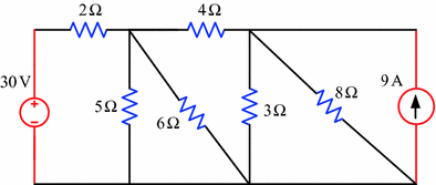
Circuit for Exercise Problem 4.45
-
4.46
Using Thevenin’s theorem calculate the power absorbed by the \(12\,{\Omega}\) resistor of the circuit in Fig. 4.122.
Fig. 4.122 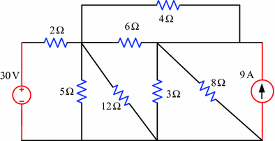
Circuit for Exercise Problem 4.46
-
4.47
Using Thevenin’s theorem calculate the current in the \(5\,{\Omega}\) resistor of the circuit in Fig. 4.123. Verify the result by PSpice simulation.
Fig. 4.123 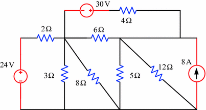
Circuit for Exercise Problem 4.47
-
4.48
Using Thevenin’s theorem find the current in the \(6\,{\Omega}\) resistor of the circuit in Fig. 4.124. Verify the result by PSpice simulation.
Fig. 4.124 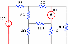
Circuit for Exercise Problem 4.48
-
4.49
Using Thevenin’s theorem find the current in \(2\,{\Omega}\) resistor of the circuit in Fig. 4.125.
Fig. 4.125 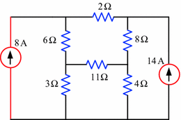
Circuit for Exercise Problem 4.49
-
4.50
Using Thevenin’s theorem determine the current in the \(12\,{\Omega}\) resistor of the circuit in Fig. 4.126. Verify the result by PSpice simulation.
Fig. 4.126 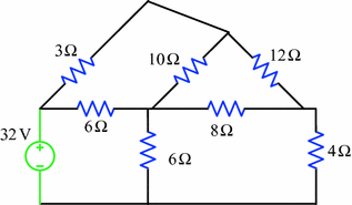
Circuit for Exercise Problem 4.50
-
4.51
Using Thevenin’s theorem calculate the current in the \(8\,{\Omega}\) resistor of the circuit in Fig. 4.127. Verify the result by PSpice simulation.
Fig. 4.127 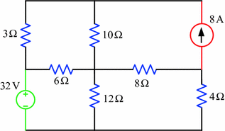
Circuit for Exercise Problem 4.51
-
4.52
Using Thevenin’s theorem find the current in the \(10\,{\Omega}\) resistor of the circuit in Fig. 4.128. Verify the result by PSpice simulation.
Fig. 4.128 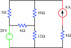
Circuit for Exercise Problem 4.52
-
4.53
Using Thevenin’s theorem determine the current in the \(12\,{\Omega}\) resistor of the circuit in Fig. 4.129. Verify the result by PSpice simulation.
Fig. 4.129 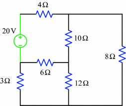
Circuit for Exercise Problem 4.53
-
4.54
Using Thevenin’s theorem calculate the current in the \(6\,{\Omega}\) resistor of the circuit in Fig. 4.130. Verify the result by PSpice simulation.
Fig. 4.130 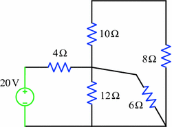
Circuit for Exercise Problem 4.54
-
4.55
Using Thevenin’s theorem find the current in the \(3\,{\Omega}\) resistor of the circuit in Fig. 4.131. Verify the result by PSpice simulation.
Fig. 4.131 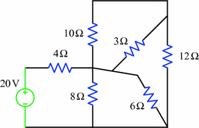
Circuit for Exercise Problem 4.55
-
4.56
Using Thevenin’s theorem determine the current in the \(8\,{\Omega}\) resistor of the circuit in Fig. 4.132. Verify the result by PSpice simulation.
Fig. 4.132 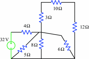
Circuit for Exercise Problem 4.56
-
4.57
Use Thevenin’s theorem to calculate the current in the \(6\,{\Omega}\) resistor of the circuit in Fig. 4.133. Verify the result by PSpice simulation.
Fig. 4.133 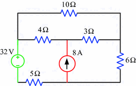
Circuit for Exercise Problem 4.57
-
4.58
Use Thevenin’s theorem to calculate the current in the \(10\,{\Omega}\) resistor of the circuit in Fig. 4.134. Verify the result by PSpice simulation.
Fig. 4.134 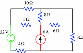
Circuit for Exercise Problem 4.58
-
4.59
Using Thevenin’s theorem determine the current in the \(10\,{\Omega}\) resistor of the circuit in Fig. 4.135. Verify the result by PSpice simulation.
Fig. 4.135 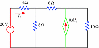
Circuit for Exercise Problem 4.59
-
4.60
Using Thevenin’s theorem calculate the current in the \(8\,{\Omega}\) resistor of the circuit in Fig. 4.136. Verify the result by PSpice simulation.
Fig. 4.136 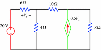
Circuit for Exercise Problem 4.60
-
4.61
Using Thevenin’s theorem calculate the current in the \(4\,{\Omega}\) resistor of the circuit in Fig. 4.137. Verify the result by PSpice simulation.
Fig. 4.137 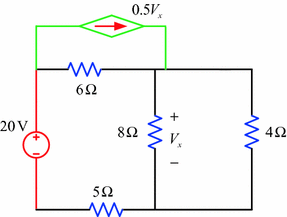
Circuit for Exercise Problem 4.61
-
4.62
Use Thevenin’s theorem to find the current in the \(5\,{\Omega}\) resistor of the circuit in Fig. 4.138. Verify the result by PSpice simulation.
Fig. 4.138 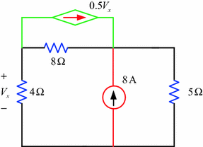
Circuit for Exercise Problem 4.62
-
4.63
Use Thevenin’s theorem to find the current in the \(4\,{\Omega}\) resistor of the circuit is shown in Fig. 4.139.
Fig. 4.139 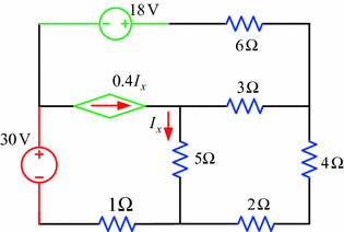
Circuit for Exercise Problem 4.63
-
4.64
Use Thevenin’s theorem to find the current in the \(6\,{\Omega}\) resistor of the circuit in Fig. 4.140.
Fig. 4.140 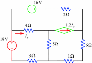
Circuit for Exercise Problem 4.64
-
4.65
Using Norton’s theorem calculate the current in the \(8\,{\Omega}\) resistor of the circuit in Fig. 4.141. Verify the result by PSpice simulation.
Fig. 4.141 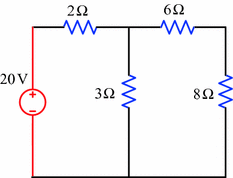
Circuit for Exercise Problem 4.65
-
4.66
Using Norton’s theorem find the current in the \(4\,{\Omega}\) resistor of the circuit in Fig. 4.142. Verify the result by PSpice simulation.
Fig. 4.142 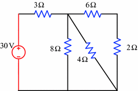
Circuit for Exercise Problem 4.66
-
4.67
Using Norton’s theorem calculate the current in the \(5\,{\Omega}\) resistor of the circuit in Fig. 4.143. Verify the result by PSpice simulation.
Fig. 4.143 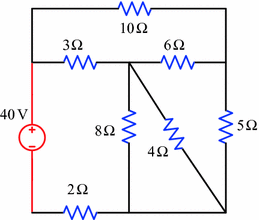
Circuit for Exercise Problem 4.67
-
4.68
Using Norton’s theorem determine the current in the \(8\,{\Omega}\) resistor of the circuit in Fig. 4.144. Verify the result by PSpice simulation.
Fig. 4.144 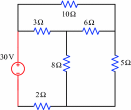
Circuit for Exercise Problem 4.68
-
4.69
Using Norton’s theorem find the current in the \(12\,{\Omega}\) resistor of the circuit in Fig. 4.145. Verify the result by PSpice simulation.
Fig. 4.145 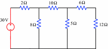
Circuit for Exercise Problem 4.69
-
4.70
Using Norton’s theorem calculate the current in the \(5\,{\Omega}\) resistor of the circuit in Fig. 4.146. Verify the result by PSpice simulation.
Fig. 4.146 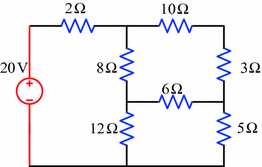
Circuit for Exercise Problem 4.70
-
4.71
Using Norton’s theorem determine the current in the \(3\,{\Omega}\) resistor of the circuit in Fig. 4.147. Verify the result by PSpice simulation.
Fig. 4.147 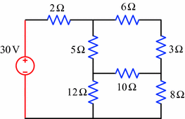
Circuit for Exercise Problem 4.71
-
4.72
Using Norton’s theorem calculate the current in the \(6\,{\Omega}\) resistor of the circuit in Fig. 4.148. Verify the result by PSpice simulation.
Fig. 4.148 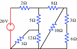
Circuit for Exercise Problem 4.72
-
4.73
Use Norton’s theorem to find the current in the \(4\,{\Omega}\) resistor of the circuit in Fig. 4.149. Verify the result by PSpice simulation.
Fig. 4.149 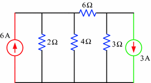
Circuit for Exercise Problem 4.73
-
4.74
An electrical circuit is shown in Fig. 4.150. Use Norton’s theorem to find the current in the \(6\,{\Omega}\) resistor and compare the result with PSpice simulation.
Fig. 4.150 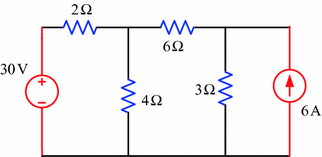
Circuit for Exercise Problem 4.74
-
4.75
Fig. 4.151 shows an electrical circuit. Calculate the current in the \(5\,{\Omega}\) resistor by using Norton’s theorem and verify the result by PSpice simulation.
Fig. 4.151 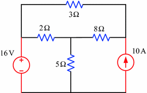
Circuit for Exercise Problem 4.75
-
4.76
An electrical circuit is shown in Fig. 4.152. Determine the current in the \(3\,{\Omega}\) resistor by using Norton’s theorem and verify the result by PSpice simulation.
Fig. 4.152 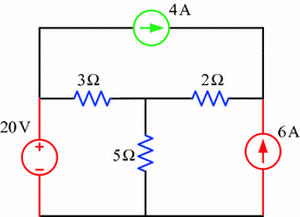
Circuit for Exercise Problem 4.76
-
4.77
Use Norton’s theorem to calculate the current in the \(3\,{\Omega}\) resistor of the circuit in Fig. 4.153. Verify the result by PSpice simulation.
Fig. 4.153 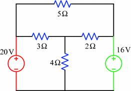
Circuit for Exercise Problem 4.77
-
4.78
An electrical circuit is shown in Fig. 4.154. Use Norton’s theorem to calculate the current in the \(5\,{\Omega}\) resistor. Verify the result by PSpice simulation.
Fig. 4.154 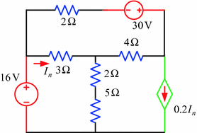
Circuit for Exercise Problem 4.78
-
4.79
Figure 4.155 shows an electrical circuit. Use Norton’s theorem to calculate the current in the \(3\,{\Omega}\) resistor. Verify the result by PSpice simulation.
Fig. 4.155 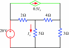
Circuit for Exercise Problem 4.79
-
4.80
Figure 4.156 shows an electrical circuit. Use Norton’s theorem to calculate the current in the \(3\,{\Omega}\) resistor. Verify the result by PSpice simulation.
Fig. 4.156 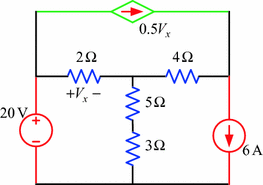
Circuit for Exercise Problem 4.80
-
4.81
Using maximum power transfer theorem calculate the load resistance R of the circuit in Fig. 4.157, and also find the maximum power.
Fig. 4.157 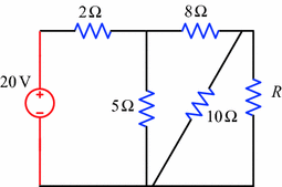
Circuit for Exercise Problem 4.81
-
4.82
Using maximum power transfer theorem determine the load resistance R of the circuit in Fig. 4.158, and also find the maximum power.
Fig. 4.158 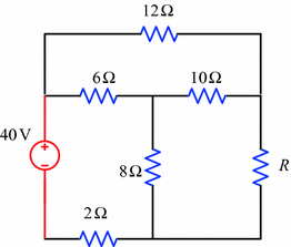
Circuit for Exercise Problem 4.82
-
4.83
Using maximum power transfer theorem calculate the load resistance R of the circuit in Fig. 4.159, and also find the maximum power.
Fig. 4.159 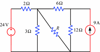
Circuit for Exercise Problem 4.83
-
4.84
Using maximum power transfer theorem calculate the load resistance R of the circuit in Fig. 4.160, and also find the maximum power.
Fig. 4.160 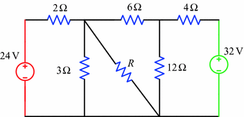
Circuit for Exercise Problem 4.84
-
4.85
Using maximum power transfer theorem calculate the load resistance R of the circuit in Fig. 4.161, and also find the maximum power.
Fig. 4.161 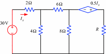
Circuit for Exercise Problem 4.85


Rights and permissions
Copyright information
© 2018 Springer Nature Singapore Pte Ltd.
About this chapter

Cite this chapter
Salam, M.A., Rahman, Q.M. (2018). Network Theorems. In: Fundamentals of Electrical Circuit Analysis. Springer, Singapore. https://doi.org/10.1007/978-981-10-8624-3_4
Download citation
DOI: https://doi.org/10.1007/978-981-10-8624-3_4
Published:
Publisher Name: Springer, Singapore
Print ISBN: 978-981-10-8623-6
Online ISBN: 978-981-10-8624-3
eBook Packages: EngineeringEngineering (R0)