
Abstract
In this research, we examine the necessary information for remotely vessel navigating and the display system for the mariner in a re-mote place. We also conduct experiments using small vessels. In remotely vessel navigating, it is important to send all information on the hull and vessel around to vessel operator at a remote location with the lowest possible delay. Since river traffic is being researched, it is targeted for remote ship navigating of small vessels in urban rivers. In this research, we examined the monitor for the ship operator for remotely vessel navigating of small vessels, and conducted the remotely vessel navigating experiments. Although it is the minimum necessary function for remotely vessel navigating, it’s possible to navigate. It is necessary to show a lot of information to the operator for safe navigation, such as distance to distant vessels, obstacles, weather, oceanic conditions etc. and consider to avoid data traffic.
You have full access to this open access chapter, Download conference paper PDF
1 Introduction
In this research, we examine the necessary information for remotely vessel navigating and the display system for the mariner in a remote place. We also conduct experiments using small vessels.
In remotely vessel navigating, it is important to send all information on the hull and vessel around to vessel operator at a remote location with the lowest possible delay. Rolls Royce [1] does research and verification on autonomous vessel and remotely vessel navigating in emergency, promoting the development of remote vessel navigating in MUNIN project [2]. The accident proportion of small vessels is high due to human error [3]. Since river traffic is being researched, it is targeted for remote ship navigating of small vessels in urban rivers.
2 Remote Navigating of Small Vessels
For remotely small vessel navigating (Fig. 1), vessel navigating function, communication function, and emergency response function are necessary. navigating and monitoring techniques are required for the marine vessel navigating function. To prevent accidents, monitoring is very important. In general, a marine vessel operator navigates while checking the surrounding environment such as height, distance of a pier, speed of another ship, weather and oceanographic information. In the case of remotely navigating, these information are also necessary. However, if the amount of data to be transmitted increases, the problems that communication delays and data losses happen. All of data must be synchronized. Therefore, it is necessary to research on information transportation and display method for the remote operator.

Small vessel (inside)
In this research, we set up an environmental display computer for processing information of monitoring, a controlling computer for autopilot on-board. Also, a display computer, a control computer and a communicating computer are installed on the remote navigate side. We conduct remotely vessel navigating experiment by controlling the control computer at a remote place.
3 Remotely Navigating System
For navigating, the autopilot system was used. This system has a generally purpose computer that can communicate with Transmission Control Protocol (TCP). From the control computer inside “RAICHO I”, information of vessel is transmitted to the control computer on the remotely navigating side, and the control commands are sent from the control computer on the remotely vessel navigating side. At the same time, the image is delivered from the environment display computer by User Datagram Protocol (UDP). A total of 5 people boarded “RAICHO I”, a person holding a small vessel license who can be a captain in the event of an emergency, one manager of the system and three guards. The pipeline of the information display is shown in Fig. 2. Experiments were conducted twice, changing information display method, remotely vessel operator.

Pipeline of the information display
4 Monitor for Remote Operator
Vessel navigating is different from driving a car. In the case of a car, the road, lane and direction are determined. Also, in places where the roads cross, traffic is controlled with signals. Although in a water area where small vessels sail, the direction of is determined, it is not as precise as a car. Also, when overtaking, it’s important to decide where can be sail to according to the size and speed of the vessel. In some cases, it meanders to avoid the pulling wave. The situation of surroundings must be watched constantly, so that the monitor is more important than using in car.
Navigating such a vessel from a remote place, the same information as actual navigating that includes navigate information and monitor information are required. Information of navigating is “vessel speed” indicating the speed of ship, “bow direction” indicating the direction that the vessel is facing, and “panoramic streaming video”, the monitor information which can overlook all directions, so that the captain can navigate a small vessel. Comparing to visual observation, the distance to objects (bridge, berthing boat) is hard to be transmitted from the image. Therefore, in addition to the necessary items for normal vessel navigating, a method for displaying distances to obstacles such as bridge piers and berths will be researched. Also, for low speed communication, the virtual environment map of the place where the vessel is located is displayed.
5 Distance Display to Object
Two cameras were used to calculate the distance from the vessel to the surroundings, fitting with fisheye lens (360° × 240°). It takes a lot of time to calculate the distance of all the pixels in the range that can be shot with camera (Fig. 3). Also, it is predicted that errors will increase due to the shake of vessel. Therefore, dividing the whole circumference by 16 and calculating the average distance within the rectangular region, the distance to the surroundings is calculated with low delay. It can be judged in a short time by indicating the calculation result whether distance is short in color (Fig. 4). While acquiring the image of the whole circumference, the calculated distance was overwrote. The distance between the two cameras is set to 95 cm so that the distance of 40 m ahead can be calculated.

Captured image from fisheye camera

Display average distance (Color figure online)
6 Low Speed Communication
Assuming a case where it is difficult to receive video due to deterioration of the communication environment, based on the position information sent from the vessel, a 3-dimensional space map based on point cloud data (Fig. 5) created in advance with a stereo camera is displayed on the marine vessel side screen. During low-speed communication, video distribution with a large amount of data is not performed, only autopilot command and vessel position information are transmitted. From the position information, the position in the virtual environment is obtained.

Point cloud data (river side)
7 Screen Evaluation Experiment for Distance Display
It is difficult to judge the distance to the obstacle from the image displaying on the screen, and whether both the steering angle and the output are appropriate, although the distance to the surrounding obstacles is displayed (Fig. 6). When navigating inside the vessel, it is easy to grasp the size and movement of the hull, but in remotely ship navigating it is difficult to grasp the surrounding environment even if the panoramic video was displayed, the evaluation of the operator is feeling uneasy as a result. In this experiment, it is not a situation where it is easy to remotely vessel navigate. It is a guide to steer and display that can grasp the movement of the hull which is necessary. Based on the results of these experiments, we reexamined the display of bearing lines, which aligns the shape of the cylindrical screen on the remote navigating side (220° in the horizontal direction) and the horizontal angle of view of the image (Fig. 7).

Screen evaluation experiment

The cylindrical screen
8 Screen Evaluation Experiment Displaying Vessel Navigating Support Information
We conducted a re-experiment in the same water area. From the previous result, the new display system (Fig. 8) was changed as follows.

New pipeline of the display system configuration
-
Draw a line indicating the bow direction and stern direction
-
Draw bearing line every 30° so that can easily specify the steering angle (Fig. 9)
Fig. 9. 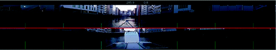
Display system
-
Vessel speed displayed on screen.

The distance was feeling easy to grasp because of the display on the large screen overall, and the vessel speed indication was a reference for vessel navigating. Especially the image of the stern was a good evaluation for judging the position of the hull when passing through a bridge or narrow water channel.
Based on the previous experimental results, we added information such as azimuth on the image so that it is easy to grasp the movement of the hull, so it was a stable remotely vessel navigating. It is necessary to research on vessel navigating support functions such as adjustment of shooting equipment, future indications to be considered, predicted moving position, indication of water depth, but we think that it’s a good result.
In the display of the surrounding conditions of the vessel, it is thought that visibility of the operator himself influenced the evaluation. In a narrow waterway sailing by a small vessel, it is necessary to secure the rearward visibility as well as the bow direction because the distance to other vessels such as the same navigation line and anti-navigation line is short. In accordance with the angle of 220° of the cylindrical screen watched by the operator, it can avoid the collision with obstacles by cutting out 220° centering on the bow and stern from the whole circumference image, reducing the movement of the head by displaying it all in two steps (Fig. 10). We believe that we can provide sufficient information to the operator. We considered that the shaking of the capture device influenced the operator, and this time the capture device was installed on the 3-axis stabilizer at remotely vessel navigating. At the time of hull shake, since the capture device moves in the horizontal direction, the center of the screen and the bow direction didn’t overlap, affecting the designation of the steering angle. It is necessary to take measures to make the bow appear in the captured image.

Panoramic images (bow/stern)
We researched on the 3-dimensional space map created beforehand based on position information of hull in case of narrow communication band instead of video. If there is no difference in the environment at the time of creating the 3-dimensional space map and the navigation, sailing is possible based on the map, but navigation information on other vessels can’t be acquired so that collision can’t be avoided. Therefore, we used Simple Lidar which can acquire distance information faster than the stereo distance calculation using the capture device, and verified whether the positional relation of surrounding obstacles can be displayed at a high speed (Fig. 11). Figure 12 shows the state of the experiment. Since it is possible to acquire the distance if it is in the range up to 30 m, it is useful when low speed navigation in a narrow channel.

Simple Lidar

The experiment
9 Conclusions
In this research, we examined the monitor for the ship operator for remote controlling of small vessels, and conducted the remote vessel controlling experiments. Although it is the minimum necessary function for remote vessel controlling, it’s possible to control. It is necessary to show the operator a lot of information for safe navigation, such as distance to other vessels, obstacles, weather, oceanic conditions, etc., and consider processing to reduce traffic. Especially, we have to pay attention to “the height” in the river. It is necessary to obtain the height information during navigation because the height of the water surface changes according to passage of time. However, we emotionally judge whether the vessel can pass through under the bridge as usual, because we can stereo graphically look at the bridge. The ship operator hesitates because he can not feel the depth and the height of the bridge even though he recognizes the bridge itself on the screen. We examine making use of 3D-panoraminc video and Head Mount Display as the solution. This is thought to be beneficial to operate vessels when they get to the shore. We also reexamine and enhance the security of remote vessel controlling system based on the result of the experiment.
References
Rolls-Royce. http://www.rolls-royce.com/. Accessed 9 Feb 2018
MUNIN Project. http://www.unmanned-ship.org/munin/. Accessed 9 Feb 2018
Japan Coast Guard: Current situation and countermeasures of marine accidents in Heisei 26. http://www.kaiho.mlit.go.jp/info/kouhou/h27/k20150318/k150318-2.pdf. Accessed 1 Feb 2018
Author information
Authors and Affiliations
Corresponding author
Editor information
Editors and Affiliations
Rights and permissions
Copyright information
© 2018 Springer International Publishing AG, part of Springer Nature
About this paper

Cite this paper
Kondo, M. et al. (2018). Monitor System for Remotely Small Vessel Navigating. In: Yamamoto, S., Mori, H. (eds) Human Interface and the Management of Information. Information in Applications and Services. HIMI 2018. Lecture Notes in Computer Science(), vol 10905. Springer, Cham. https://doi.org/10.1007/978-3-319-92046-7_35
Download citation
DOI: https://doi.org/10.1007/978-3-319-92046-7_35
Published:
Publisher Name: Springer, Cham
Print ISBN: 978-3-319-92045-0
Online ISBN: 978-3-319-92046-7
eBook Packages: Computer ScienceComputer Science (R0)