
Abstract
In the previous chapters, current interruption in switchgear with mechanically opening contacts has been considered, and important parameters of the current interruption process have been introduced. It has been explained that current waveform and amplitude as well as steepness and amplitude of the transient recovery voltage constitute the critical stresses to the switching arc and have a decisive impact on whether an interruption will succeed or fail. These stresses are very dependent on the network configuration where the switching device is employed. On the other hand, switching operations may expose other components in the network to higher stresses, such as overvoltages and overcurrents.
This is a preview of subscription content, log in via an institution.
Buying options
Tax calculation will be finalised at checkout
Purchases are for personal use only
Learn about institutional subscriptionsReferences
Blackburn JL (1993) Symmetrical components for power system engineering. Marcel Dekker Inc., New York
Grainger JJ, Stevenson WD (1994) Power system analysis. McGraw-Hill Inc., New York
IEC 62217-100 (2008) High voltage switchgear and controlgear, part 100: alternative current circuit breakers
IEC 62271-103 (2011) High voltage switchgear and controlgear, part 103: switches for rated voltages above 1 kV up to and including 52 kV
Jonsson E (2014) Load current interruption in air for medium voltage ratings. Doctoral thesis 2014:83, Norwegian University of Science and Technology (NTNU)
IEEE standard C37.083 (1999) IEEE guide for synthetic capacitive current switching tests
CIGRÉ WG 13.02 (1980) Interruption of small inductive currents. Electra 72:73–103
Author information
Authors and Affiliations
Corresponding author
Exercises
Exercises
Problem 1
The circuit of Fig. 3.54 shows a three-phase system with a three-phase-to-ground terminal short circuit.. The breaker has received a command signal for opening; the arc in phase R has extinguished, and this pole can be considered open. The two other circuit breaker poles of phases S and T continue to carry current through an electric arc.

First figure of problem 1
The network neutral point is connected to ground through the impedance L g , and the short circuit impedance is L. The capacitance between phases is C p , and the phase-to-ground capacitance is C g . The source voltage of phase R is given as: \(u_{pR} (t) = \sqrt 2 \cdot U_{p} \cdot \,\cos (\omega t)\).
-
1.1
The single-phase equivalent circuit seen from the first pole to clear (between R and R’) is shown in Fig. 3.55.
Fig. 3.55 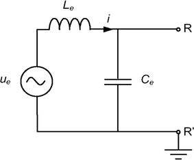
Second figure of problem 1
Show that the equivalent inductance and capacitance become:
$$L_{e} = \, L \cdot \frac{{L + 3 \cdot L_{g} }}{{L + 2 \cdot L_{g} }}$$$$C_{e} = \, 2 \cdot C_{p} + C_{g}$$ -
1.2
Please calculate the equivalent voltage u e (t) for the simplified case when L g ≫ L.
-
1.3
Assume that the breaker pole of phase R has interrupted at current zero at t = 0.
With basis in the single-phase equivalent circuit, derive an expression for the transient recovery voltage u b (t) over the first phase to clear, i.e. across RR’.
Determine the peak value of the recovery voltage in the first phase to clear when \(\omega^{2} L_{e} C_{e} \ll 1\)
In the circuit representation above, the resistances have not been considered. What will the effects on the recovery voltage as a function of time be of including the resistances?
-
1.4
Assume that the same fault happens in a directly grounded three-phase system (i.e. L g = 0). How large will the peak value of the recovery voltage of the first-phase-to-clear be in this case? Explain briefly.

Problem 2
-
2.1
Explain briefly how the current injection method can be used to calculate the recovery voltage across a breaker.
-
2.2
The principle of current injection can also be used in practical measurement for measuring the recovery voltage across a breaker installed in a power system. Describe briefly how this can be achieved in practice. What are the weaknesses and strengths of this method?
-
2.3
Figure 3.56 shows a circuit breaker that interrupts a large inductive current caused by a terminal fault. Use the principle of current injection to estimate the recovery voltage across the circuit breaker. The power frequency current flowing through the capacitor C is assumed to be negligible.
Fig. 3.56 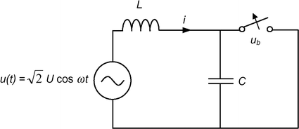
Figure of problem 2
-
2.4
During opening operation, the moving contact of the breaker has a constant speed of 5 m/s. In the first milliseconds after the electric arc is extinguished, the dielectric strength of the contact gap is assumed to be 20 kV/mm. At what time do the contact members have to separate to avoid dielectric re-ignition after the first zero crossing?
Use L = 30 mH, C = 5.3 µF, U = 177 kV and ω = 100π.

Problem 3
The circuit diagram in Fig. 3.57 can be used to analyse the interruption of a capacitive current. The capacitive load is given as C L and is much larger than the network’s capacitance to ground C n . The current interruption takes place at current zero crossing.

Figure of problem 3
-
3.1
Give some examples of where capacitive current interruption occurs in electric power systems. What are typical current magnitudes?
Sketch the waveforms of the current through the circuit breaker and the voltages at the left and right hand sides of the circuit breaker (u l and u r respectively) in the time period from a quarter of a power cycle before interruption and until a half cycle after interruption. Assume that the line impedance is negligible compared to the impedance of the capacitive load.
Find an expression for the recovery voltage across the breaker. At what time does the recovery voltage reach its maximum value? How large is this maximum value?
-
3.2
After the contact members have been separated the movable member has a constant speed of 5 m/s. In the first power cycles after interruption the dielectric strength of the contact gap is assumed to be 15 kV/mm. At what time the contact members have to separate to avoid a re-strike? Assume U = 300 kV.
Assume that the breaker re-strikes at the instant when the amplitude of the recovery voltage has its maximum value. Describe how this gradually can lead to over-voltages that are much larger than the source voltage.
-
3.3
The breaker interrupts at the first current zero crossing. Assume that the impedance due to the inductance L is not negligible compared to the load impedance. (C n remains much smaller than C L .)
Establish the network equations for the source side of the system and find an expression for the voltage on the left hand side of the breaker u l after the interruption. Find also an expression for the voltage at the right hand side of the breaker u r , and for the recovery voltage across the breaker.
Use L = 1 H, C L = 2 μF, C n = 0.01 μF, U = 300 kV and sketch the recovery voltage in the first half power cycle after the interruption. Assume that the breaker does not re-strike and that resistive losses result in the transient part being damped out within the first quarter of the power cycle after the interruption.
The dielectric stresses on the breaker are now changed compared to what is the case when the assumptions in 3.1 are valid. What two differences are important with respect to the probability of getting a re-strike? How will the interruption process proceed if the contact separates 1 ms before the current zero crossing and the contact speed and dielectric strength in the gap are as described in 3.2?
Problem 4
What is meant by transient and stationary recovery voltages in the context of current interruption? What normally determines the recovery voltage?
Which two parameters/properties of the recovery voltage are the most decisive ones with regard to how difficult an interruption becomes?
The amplitude of the current that is interrupted also influences on how difficult the interruption becomes. Explain briefly why it is usually more difficult to interrupt a large current than a small one.
Problem 5
-
5.1
The circuit diagram shown in Fig. 3.58 will be used to examine recovery voltages. Assume that the arc voltage can be neglected and that the power frequency currents flowing through the capacitances C 1 and C 2 are negligible. Interruption takes place at the natural current zero crossing. The voltages at the left and right hand sides of the breaker are u l and u r , respectively.
Fig. 3.58 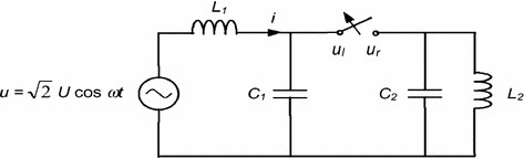
Figure of problem 5
Establish the network equations for the left hand side of the system (source side) and derive an expression for the voltage u l after the interruption.
-
5.2
Establish the circuit equations for the right hand side of the breaker (load side) and find an expression for the voltage u r after the interruption.
Assume that \(\omega^{2} L_{1} C_{1} \ll 1\) and that the resonance frequencies at both the source and load side are much higher than the power frequency of the system ω. Show that the recovery voltage just after the interruption can be expressed as:
$$u_{b} \left( t \right) = \sqrt 2 \,U\left( {1 - a_{1} \cos \omega_{1} t - a_{2} \cos \omega_{2} t} \right)$$where a 1 and a 2 are constants determined by the network inductances, and ω 1 and ω 2 are the resonance frequencies of the source and load sides of the network, respectively.

Problem 6
-
6.1
Figure 3.59 shows a simplified single phase circuit diagram for a 50 Hz grid with an almost entirely inductive load given as L = 63.7 mH. The RMS value of the voltage source is U = 12 kV. The short circuit inductance L sc = 1.6 mH, and the capacitance across the load is C l = 4 nF.
Fig. 3.59 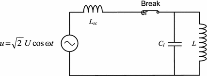
Figure of problem 6
What is the load current, and how large does the stationary short circuit current become in the case of a terminal fault?
-
6.2
The breaker opens to interrupt a load current. Derive an expression for the recovery voltage when assuming that the current is interrupted at its natural current zero crossing.
Assume here and for the rest of this exercise that arc voltage can be ignored, and that only negligible currents flow through the capacitances before interruption.
Sketch the waveform of the recovery voltage with the given circuit parameters when assuming that the transient part is damped by resistances in the circuit (not shown in the circuit diagram.)
-
6.3
Assume now that the current is not interrupted at its natural zero crossing, but that the current is chopped at i 0 = −10 A just before the zero crossing.
Find an expression of the recovery voltage, and show that it will have an extra term equal to
$$i_{0} \sqrt {\frac{L}{{C_{l} }}} \sin \frac{t}{{\sqrt {LC_{l} } }}$$Compare to the case without current-chopping in 6.1, when the small delay between the time of chopping and the time of the maximum circuit voltage is neglected.
-
6.4
As a third case, we will look into the interruption of a terminal fault the circuit above. To get a physically correct circuit diagram a capacitance of C n = 4 μF must be added between the source side and ground.
Derive an expression for the recovery voltage when assuming that interruption occurs at the natural current zero crossing.
Use the given values of the circuit parameters and draw the shape of the recovery voltage when the transients are damped by the resistances in the circuit.

Problem 7
The circuit diagram of Fig. 3.60 is the simplified version of a single phase circuit being used for type testing of medium voltage load break switches.

Figure of problem 7
The supply side consists of a 50 Hz voltage source, a short circuit inductance L sc and a capacitance C. The power frequency current flowing through the capacitance is negligible.
The load consists of a resistance R in parallel with an inductance L l .
According to the standard, the following conditions should be satisfied:
-
(i)
The supply side should constitute 15% of the total 50 Hz impedance of the circuit
-
(ii)
The load side impedance should have a power factor of \(\sqrt 2 /2\,\)
-
7.1
A single phase LBS with voltage rating of U n = 24 kV and current rating of I n = 630 A should be tested.
Determine the values of the components in the test circuit, and show that they become L sc = 18.2 mH, R = 47.9 Ω and L l = 152 mH.
-
7.2
Assume that the arc voltage is negligible compared to the system voltage, and that the current has been interrupted at its natural zero crossing.
Derive an expression for the voltage u l on the load side of the LBS after interruption.
Explain briefly why the voltage waveform becomes like this; what happens in the load side circuit?
-
7.3
Set C = 0.35 μF. Determine the frequency of the supply side contribution to the transient recovery voltage.
If the interruption fails by restrike/re-ignition after around 100–200 μs, which part of the circuit—supply side or load side—is most to blame? Explain briefly (An accurate mathematical analysis is not required; assessments based on semi-quantitative estimates suffice).
Problem 8
The circuit diagram of Fig. 3.61 shows a single-phase power circuit with a resistive load, R. The circuit is supplied by a 50 Hz AC voltage source with the peak voltage U. L is the inductance of the line and C is the capacitance to ground.

Figure of problem 8
-
8.1
L = 6.37 mH, R = 3.46 Ω, C = 4 μF and U = 12 kV. What is the stationary load current?
What is the short circuit current in the case of a terminal fault?
What is the ratio between the short circuit current and the load current of this circuit? How does this compare to a typical power circuit?
-
8.2
The breaker in the circuit diagram above is requested to open and interrupt a load current, and by chance the contacts separate exactly as the source voltage has its maximum. An arc ignites and burns until the first current zero crossing. Draw the waveforms of the source voltage and of the current flowing through the circuit in the time interval from contact separation and till the arc quenches. How long is the arcing time?
Hint: The phase shift angle ϕ is given by
$$\text{tan}\phi = \frac{{Im\{ Z_{load} \} }}{{Re\{ Z_{load} \} }}$$(3.101)where \(Im\left\{ {Z_{load} } \right\},\) and \(Re\{ Z_{load} \}\) are the imaginary and real components of the load impedance, respectively.
-
8.3
Set up the circuit equations and derive an expression for the recovery voltage, i.e., the voltage that builds up across the breaker contacts after the arc has extinguished.
Hints: The capacitance must now be included.
Shift the time axis by: \(\frac{2}{3}\pi\) , so that t = 0 corresponds to the time when the arc is extinguished, that is, let the source voltage be:
$$u = U\,\cos \left( {\omega t + \frac{2}{3}\pi } \right)$$(3.102)-
The transient solution is assumed to be of the form:
$$u_{t} = A \cdot \,\sin \frac{t}{{\sqrt {LC} }} + B \cdot \,\text{cos}\frac{t}{{\sqrt {LC} }}$$(3.103) -
After the current has been interrupted there will be no voltage across the resistive load on the right side of the breaker (u r = 0)
-
-
8.4
-
(a)
What are the frequencies of the transient and stationary parts of the recovery voltage?
-
(b)
What are the maximum amplitudes of the transient and stationary parts of the recovery voltage? Sufficient accuracy is obtained by only including the dominating terms.
Sketch the waveform of the recovery voltage for the first half power cycle assuming that the transient part is damped out within this time interval. Is this a difficult switching duty for the breaker? Explain briefly.
-
(a)
Problem 9
In the circuit shown in Fig. 3.62, a circuit breaker is used for switching of a capacitor bank. If the initial charge of the capacitor bank (C b ) is zero,

Figure of problem 9
-
9.1
Derive an expression for the inrush current flowing through the capacitor bank, when the circuit breaker is closed at t = 0.
-
9.2
Discuss the impact of power network frequency (ω) and short circuit current of the network on the amplitude and frequency of the inrush current.
-
9.3
In the circuit of Fig. 3.62, assume U = 72 kV:
-
Calculate the short circuit inductance (L sc ), if the short circuit current of this network is 40 kA.
-
Calculate the capacitance of the capacitor bank (C b ), if the rated current of the capacitor bank is 630 A.
-
Consider that a pre-strike occurs by closing operation at a distance of 4 mm in this circuit breaker. If the closing velocity is 1 m/s, calculate the total energy dissipated in the pre-arc. The arc voltage is constant (300 V).
-
Problem 10
In Fig. 3.63, a high voltage circuit breaker is used to interrupt a short circuit current caused by a terminal fault. The circuit breaker is connected to a busbar, which is connected to two other transmission lines with wave impedances of R 0 and wave propagation velocity of v. The lengths are L 1 and L 2.

Figure of problem 10
-
10.1
Please draw a simple equivalent circuit, which can be used for transient recovery voltage calculations for the circuit breaker. Note that, for this purpose, transmission lines are modelled by their wave impedances.
-
10.2
Derive the governing differential equation for the equivalent circuit with appropriate initial conditions.
-
10.3
Explain qualitatively how the transient recovery voltage looks like, considering the solution of the simple differential equation and wave propagation along the transmission lines.
-
10.4
Calculate the initial rate of rise of recovery voltage just after current zero, if U = 245 kV, Lsc =45 mH, R0 = 400 Ω and Cp= 100 nF.
Rights and permissions
Copyright information
© 2017 Springer International Publishing AG
About this chapter
Cite this chapter
Niayesh, K., Runde, M. (2017). Application of Switching Devices in Power Networks. In: Power Switching Components. Power Systems. Springer, Cham. https://doi.org/10.1007/978-3-319-51460-4_3
Download citation
DOI: https://doi.org/10.1007/978-3-319-51460-4_3
Published:
Publisher Name: Springer, Cham
Print ISBN: 978-3-319-51459-8
Online ISBN: 978-3-319-51460-4
eBook Packages: EnergyEnergy (R0)