
Abstract
Aerobic biological processes have a long history of use for treatment of wastewaters in cities and urban areas of the United States and abroad. Application of aerobic treatment in decentralized systems evolved in an attempt to produce a higher quality effluent than that typically produced by a septic tank or other anaerobic unit operation. Aerobic treatment of wastewater is capable of producing an advanced secondary effluent that can enable surface discharge and reuse options. Chapter 7 describes the principles and processes involved in aerobic biological treatment and the design and implementation of aerobic treatment units using bioreactors to achieve organic matter removal and nitrification. Biological treatment for enhanced nutrient removal is covered in Chap. 13.
Access this chapter
Tax calculation will be finalised at checkout
Purchases are for personal use only
References
References cited in Chap. 7 are listed along with other references that have content relevant to the topics covered in Chap. 7.
National Environmental Services Center (2005) Aerobic treatment units: an alternative to septic systems. Pipeline 16(3):8
Converse JC (2004) Effluent quality from ATUs and packed bed filters receiving domestic wastewater under field conditions. In: Proceedings of the Tenth National Symposium on Individual and Small Community Sewage Systems. American Society of Agricultural Engineers, St. Joseph, MI, pp 552–579
Crites RW, Tchobanoglous G (1998) Small and decentralized wastewater management systems. Chapter 7—Biological treatment and nutrient removal. McGraw-Hill, New York, 1084 pp
Grady CPL, Daigger GT, Love NG, Filipe CDM (2011) In: Biological wastewater treatment, 3rd edn. CRC, Boca Raton, 991 pp
Ivery G (1996) Aerobic treatment units (ATUs): Appropriate technology for on-site wastewater treatment and re-use. Desalination 106(1996):295–303
Jantrania AR, Gross MA (2006) Advanced onsite wastewater systems technologies. CRC Press, Boca Raton, FL, 288 pp
Kiss A, Hai FI, Nghiem LD (2011) Roadside rest area wastewater treatment system: performance evaluation and improvement. Desalin Water Treat 32:389–396
Tchobanoglous G, Stensel HD, Burton F, Tsuchihashi R (2014) In: Wastewater engineering: treatment and resource recovery, 5th edn. McGraw-Hill Education, Columbus, 2048 pp
Tyagi VK, Lo S-L (2013) Sludge: a waste or renewable source for energy and resources recovery? Renew Sust Energ Rev 25(2013):708–728
USEPA (2000a) Decentralized systems technology fact sheet: aerobic treatment. U.S. Environmental Protection Agency, EPA 832-F-00-031, 8 pp
USEPA (2000b) Wastewater technology fact sheet: oxidation ditches. U.S. Environmental Protection Agency, EPA 832-F-00-013, 6 pp
USEPA (2002) Onsite wastewater treatment systems manual. U.S. Environmental Protection Agency, EPA/625/R-00/008. http://www.epa.gov/ORD/NRMRL/Pubs/625R00008/625R00008.htm
Author information
Authors and Affiliations
Slides of Chapter 7 Decentralized Water Reclamation
Slides of Chapter 7 Decentralized Water Reclamation
7.1.1 Chapter 7: Treatment using Aerobic Bioreactors
Contents
-
7-1.
Introduction
-
7-2.
Treatment performance
-
7-3.
Principles and processes
-
7-4.
Design and implementation
-
7-5.
Summary
-
7-6.
Example problems
7.1.1.1 7-1. Introduction
-
■ Aerobic biological treatment of wastewaters
-
• Primary treated wastewaters normally contain dissolved and colloidal organic matter and fine particulates that are not removed during primary treatment
-
• Aerobic biological processes can provide further treatment of primary effluents such as septic tank effluent
-
• Aerobic biological processes can be used to achieve:
-
○ Advanced secondary treatment
-
* Removal of soluble and colloidal organic matter (BOD)
-
* Removal of colloidal and fine particulates (TSS)
-
* Nitrification of ammonia (NH4 +)
-
-
○ Nutrient removal
-
* Aerobic treatment can also be used for enhanced removal of nitrogen and phosphorus as described in Chap. 13
-
-
-
-
■ Treatment using aerobic bioreactors
-
• Aerobic treatment exploits microorganisms (biomass) that can use constituents in wastewater as a source of carbon and nutrients and also energy for growth
-
• Aerobic treatment requires a flow regime to contact biomass with wastewater while maintaining proper aeration status
-
○ This can be accomplished in bioreactors which can be classified based on biomass and reactor type (Fig. 7.1)
Fig. 7.1 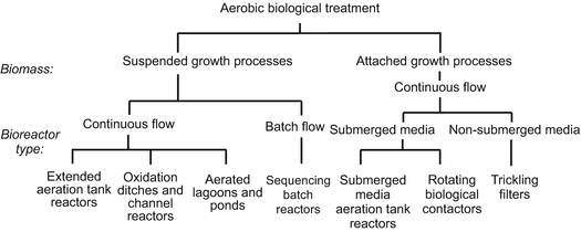
Classification of aerobic biological treatment methods based on how the biomass is contacted with the wastewater within different types of bioreactorsNote: in addition to the methods shown in Fig. 7.1 there are other treatment methods that rely on aerobic biological processes that are covered in other chapters, including porous media biofilters (Chap. 8), membrane bioreactors (Chap. 9), constructed wetlands (Chap. 10), soil-based treatment operations (Chaps. 11 and 12), nutrient reduction methods (Chap. 13), and waste solids and residuals management methods (Chap. 15)
-
○ Aerobic treatment of wastewater in a bioreactor is generally based on a 100+-year old process known as “activated sludge”
-
-
• Chapter 7 is focused on aerobic treatment in bioreactors such as included in Fig. 7.1
-
○ There are other treatment operations that rely on aerobic biological processes that are covered in other chapters
-
-
-
■ Activated sludge processes
-
• “Activated microbial biomass” involves a consortium of bacteria and other microorganisms that are contacted with wastewater and aerated to support microbial growth
-
○ In an aerated tank the microbial biomass and wastewater are referred to as “mixed liquor” (Fig. 7.2)
Fig. 7.2 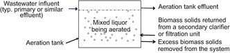
Illustration of mixed liquor being aerated in an aeration tank
-
* Aeration tank is used throughout Chap. 7 to denote an aerated zone, compartment, basin, channel, etc.
-
-
○ Mixed liquor volatile suspended solids (MLVSS) is often used as a measure of biomass concentration
-
-
• Several terms are used to describe how long biomass solids remain in the biological treatment system
-
○ Sludge age
$$ \mathrm{Sludge}\kern0.5em \mathrm{age}\kern0.5em \left(\mathrm{days}\right)=\frac{\mathrm{Total}\kern0.5em \mathrm{lb}\kern0.5em \mathrm{o}\mathrm{f}\kern0.5em \mathrm{MLVSS}\kern0.5em \mathrm{in}\kern0.5em \mathrm{aeration}\kern0.5em \mathrm{t}\mathrm{ank}}{\mathrm{lb}/\mathrm{day}\kern0.5em \mathrm{o}\mathrm{f}\kern0.5em \mathrm{V}\mathrm{S}\mathrm{S}\kern0.5em \mathrm{in}\mathrm{f}\mathrm{luent}\kern0.5em \mathrm{t}\mathrm{o}\kern0.5em \mathrm{t}\mathrm{he}\kern0.5em \mathrm{system}} $$ -
○ Solids Retention Time (SRT)
$$ \mathrm{S}\mathrm{R}\mathrm{T}\kern0.5em \left(\mathrm{days}\right)=\frac{\mathrm{Total}\kern0.5em \mathrm{lb}\kern0.5em \mathrm{of}\kern0.5em \mathrm{MLVSS}\kern0.5em \mathrm{in}\kern0.5em \mathrm{aeration}\kern0.5em \mathrm{tank}}{\mathrm{lb}/\mathrm{day}\kern0.5em \mathrm{of}\kern0.5em \mathrm{V}\mathrm{S}\mathrm{S}\kern0.5em \mathrm{wasted}\kern0.5em \mathrm{from}\kern0.5em \mathrm{the}\kern0.5em \mathrm{system}} $$ -
○ Mean Cell Residence Time (MCRT)
$$ \mathrm{MCRT}\kern0.5em \left(\mathrm{days}\right)=\frac{\mathrm{Total}\kern0.5em \mathrm{lb}\ \mathrm{of}\kern0.5em \mathrm{MLVSS}\kern0.5em \mathrm{in}\kern0.5em \mathrm{aeration}\kern0.5em \mathrm{tank}}{\mathrm{lb}/\mathrm{day}\kern0.5em \mathrm{of}\kern0.5em \mathrm{V}\mathrm{S}\mathrm{S}\kern0.5em \mathrm{wasted}\kern0.5em \mathrm{and}\kern0.5em \mathrm{in}\kern0.5em \mathrm{clarifier}\kern0.5em \mathrm{effluent}} $$ -
○ For practical purposes, SRT ≈ MCRT
-
-
• Activated sludge processes for secondary treatment in a bioreactor can be classified based on:
-
○ The rate of organic matter removal from the liquid wastewater
-
○ If nitrification occurs during aeration (NH4 + → NO3 −)
-
-
• Classification based on organic matter removal and nitrification—examples of two different options
-
○ High rate processes that are non-nitrifying: These processes have a high treatment capacity (e.g., gal/day per ft3 of reactor volume) for organic matter removal but do not achieve nitrification
-
○ Low rate processes that are nitrifying: These processes have a lower treatment capacity for organic matter removal but they do achieve nitrification
-
* In low rate processes wastewater is typically aerated over an extended period of time
-
* Low rate processes that are nitrifying are often used in decentralized systems
-
-
-
-
■ Basic features of aerobic treatment units
-
• For decentralized systems, aerobic biological treatment is often implemented using aerobic treatment units (ATUs)
-
• ATUs are often implemented as a packaged unit such as illustrated in Figs. 7.3, 7.4 and 7.5
Fig. 7.3 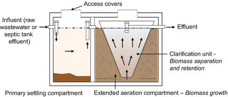
Illustration of an ATU with an integrated primary settling unit, suspended growth bioreactor, and secondary clarifier
Fig. 7.4 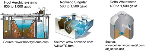
Examples of three commercially available ATUs that utilize submerged growth bioprocesses.
Note: many of these ATU manufacturers also provide larger package plant ATUs that handle flows up to 100,000 gal/day or more. Refer to the company websites for more information. Source: www.hootsystems.com. Source: www.norweco.com/wiki/ATS.htm. Source: www.deltaenvironmental.com/df_series.asp
Fig. 7.5 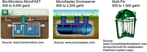
Examples of three commercially available ATUs that utilize attached growth bioprocesses.
Note: many of these ATU manufacturers also provide larger package plant ATUs that handle flows up to 100,000 gal/day or more. Refer to the company websites for more information. Source: www.biomicrobics.com Source: www.microseptec.com. Source: www.consolidatedtreatment.com/products/multi-flo-wastewater-treatment-system.aspx
-
• Examples of commercially available small ATUs
-
-
■ Where is aerobic treatment used?
-
• Where secondary treatment is warranted, for example:
-
○ For treatment of wastewaters with high organic matter content such as those from restaurants and other commercial sources
-
○ To enable or enhance soil-based treatment operations
-
* Enable higher rate subsurface infiltration systems
-
* Reduce the separation distance to shallow groundwater or setback distance to a property line
-
-
○ To enable surface discharge and reuse of effluent which often requires secondary or higher quality effluent
-
-
• Aerobic treatment is used in decentralized systems serving:
-
○ Residential units and developments
-
○ Commercial and institutional buildings and developments
-
○ Mixed-use developments, small towns and urban areas
-
-


7.1.1.2 7-2. Treatment Performance
-
■ Aerobic treatment units are normally used to achieve advanced secondary treatment
-
• BOD and TSS removal
-
○ Biodegradable organics (dissolved and colloidal) are converted to cell mass and CO2 which can be separated from the effluent
-
○ Reduced inorganics which can exert BOD can be converted to oxidized forms (e.g., NH4 + to NO3 −)
-
○ TSS in the form of colloidal and fine particulates are biodegraded and/or removed by flocculant settling
-
-
• Nitrification of ammonia
-
• During normal secondary treatment there can also be some degree of removal of nutrients and pathogens
-
○ Aerobic treatment units can be specifically designed and operated to achieve enhanced removal of N and P (Chap. 13)
-
-
-
■ Treatment efficiency
-
• Treatment efficiency is illustrated in Fig. 7.6 and can be determined using Eq. 7.1
Fig. 7.6 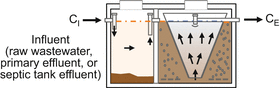
Illustration of treatment efficiency achieved within an aerobic treatment unit
-
○ Application of Eq. 7.1 can be limited if the composition of the influent (CI) to the ATU is unknown or has to be assumed
$$ {\mathrm{R}}_{\mathrm{E}}=\left(\frac{{\mathrm{C}}_{\mathrm{I}}-{\mathrm{C}}_{\mathrm{E}}}{{\mathrm{C}}_{\mathrm{I}}}\right)\times 100\% $$(7.1)Where:
-
RE = removal efficiency (%)
-
CI = influent concentration (mg/L)
-
CE = effluent concentration (mg/L)
-
-
-
-
■ Aerobic treatment efficiencies for constituents of potential concern are presented in Table 7.1
Table 7.1 Representative treatment efficiency achieved within a well-designed and operated aerobic unit -
■ Aerobic treatment unit effluent composition
-
• Factors affecting treatment efficiency and effluent composition
-
○ Source and consistency of the influent to an ATU
-
○ ATU design and operating conditions
-
* Bioreactor type and sizing
-
* Actual flow and organic load versus design
-
* Clarifier sizing and solids separation efficiency
-
* Temperatures and effects on bioprocesses
-
-
○ Degree of routine operation and maintenance that is provided
-
○ ATU treatment efficiency can decline during upsets, e.g.:
-
* During periods of very low or high flow, low or high pH, or elevated biotoxics (e.g., quaternary ammonium salts or high chlorine)
-
-
-

7.1.1.3 7-3. Principles and Processes
-
■ Biological treatment depends on a healthy biosystem
-
• A “healthy” biological treatment system involves a consortium of microorganisms that help achieve treatment efficiency and settleability and retention of biomass
-
• The nature of the consortium depends on conditions in the biological system and the length of time the microorganisms spend in the system (Fig. 7.7)
-
• Bacteria are important for aerobic biological treatment
-
○ Bacteria and other organisms grow in the biological system
-
○ Growth normally occurs in phases depending on food supply as shown in Fig. 7.8
Fig. 7.8 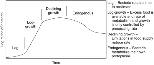
Illustration of bacterial growth as a function of time and food supply
-
-
-
■ Biological treatment depends on bacterial metabolism
-
• Metabolism requires a source of energy and carbon
-
• Most biological processes used for waste treatment are driven by heterotrophic bacteria (Table 7.2)
Table 7.2 Classification of biological processes based on sources of energy and carbon -
○ Energy is derived from the transfer of electrons from a donor to an acceptor and carbon is derived from organic matter
-
○ Heterotrophic modes of metabolism are summarized in Table 7.3
Table 7.3 Features of heterotrophic modes of metabolism involved in aerobic treatment processes
-
-
• Equation 7.2 is a simplified reaction (not balanced) for aerobic biodegradation of organic matter (substrate) in wastewater
$$ \mathrm{Organic}\kern0.5em \mathrm{substrate}\kern0.5em +\kern0.5em \mathrm{oxygen}\Rightarrow \mathrm{energy}+\mathrm{cells}+\mathrm{other}\kern0.5em \mathrm{products} $$$$ {\mathrm{C}}_{10}{\mathrm{H}}_{19}{\mathrm{O}}_3\mathrm{N}\kern0.5em +\kern0.5em {\mathrm{O}}_2\Rightarrow {\mathrm{C}}_5{\mathrm{H}}_7{\mathrm{O}}_2{\mathrm{NP}}_{0.08}+{\mathrm{C}\mathrm{O}}_2+{\mathrm{H}}_2\mathrm{O}+{\mathrm{NH}}_3 $$(7.2)-
○ The level of substrate (S) available affects the reaction
-
* Assuming substrate is represented by BOD5
-
* With low BOD5 levels
-
– To generate energy, a greater proportion of BOD5 is used to generate CO2 and fewer cells are produced
-
-
* With high BOD5 levels
-
– Since there is adequate BOD5 to produce energy, more cells are produced
-
-
-
-
-
■ Cell growth and substrate utilization
-
• Bacterial cell growth and wastewater substrate used in aerobic bioreactors are often represented by lumped parameters
-
○ For the concentration of cells in the aeration tank:
-
* Volatile suspended solids (VSS) are typically used
-
– For the contents of an aeration tank this is often referred to as “mixed liquor VSS” or MLVSS
-
-
* MLVSS is a fraction of the mixed liquor suspended solids (MLSS)
-
– For domestic wastewater in the United States, MLVSS is typically about 65–80 % of the MLSS
-
– For some wastewaters, MLVSS can be different (e.g., in Bangkok MLVSS can be only 45–55 % of the MLSS)
-
-
-
○ For the concentration of substrate in the aeration tank:
-
* Biochemical oxygen demand (BOD)
-
* Chemical oxygen demand (COD)
-
-
-
• Growth reactions are important to treatment
-
○ Primary growth reactions target dissolved organic matter
-
* Organic matter is degraded to provide C for cell growth and oxidized to CO2 and H2O to provide energy
-
-
○ Growth reactions can also achieve removal of nutrients
-
* Transformation and removal of nitrogen
-
– Nitrification
-
NH4 + is converted to NO3 −
-
Organic-N can be converted to NH4 + and then to NO3 −
-
-
– Denitrification
-
NO3 − is converted to N2O and N2 gas
-
-
-
* Removal of phosphorus
-
– P can be incorporated into new cells
-
– Excess P is stored in cells under certain conditions
-
-
-
-
• During aerobic treatment, growth is promoted
-
○ Dissolved oxygen (DO) is provided to support bacterial growth
-
○ Growth involves use of substrate in the wastewater
-
* Substrate is typically viewed as a constituent of concern (e.g., BOD or COD)
-
* Organic substrate is biodegraded to yield carbon
-
* Energy is derived by transferring electrons, e.g.:
-
– From organic matter to O2
-
– From NH4 +, Fe2+ or S2− to O2
-
-
-
○ Rates of growth and substrate utilization are related
-
* Higher growth rate equals a higher substrate utilization rate
-
* Substrate utilization equates to treatment (e.g., BOD or COD removal)
-
-
-
-
■ Kinetics of cell growth and substrate utilization
-
• Some substrate (organic matter) is converted to new cells and some is oxidized to inorganic and organic end products
-
• The kinetics of growth and utilization are complicated, but underpin aerobic treatment process function and performance
-
• The rate of cell growth and substrate utilization are related
-
○ The rate of growth needs to account for (1) energy required for cell maintenance and (2) cell death and loss by predation
-
* Lump these factors as “endogenous decay”
-
-
○ Net cell growth occurs and some biomass needs to be wasted periodically to sustain proper bioreactor function and performance
-
○ Temperature effects on rates can be substantial
-
-
• Summary of kinetics of growth and substrate utilization
-
○ In a batch or continuously mixed culture of bacteria, with no food supply limitations, growth can be defined by Eq. 7.3
-
○ If substrate or nutrients are limiting, the specific growth rate can be defined by Eq. 7.4 (Fig. 7.9)
Fig. 7.9 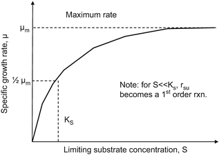
Illustration of specific growth rate as a function of substrate concentration
$$ {\mathrm{r}}_{\mathrm{g}} = \upmu \mathrm{X} $$(7.3)$$ \upmu = {\upmu}_{\mathrm{m}}\left(\frac{\mathrm{S}}{{\mathrm{K}}_{\mathrm{S}}+\mathrm{S}}\right) $$(7.4)Where:
-
rg = rate of bacterial growth (mgVSS/L per day)
-
μ = specific growth rate (day−1)
-
μm = maximum specific growth rate (day−1)
-
X = concentration of bacteria (mgVSS/L)
-
S = concentration of growth limiting substrate (mgBOD or COD/L)
-
KS = substrate concentration at 50 % of μm (mg/L)
-
-
○ Combining Eqs. 7.3 and 7.4 yields the rate of growth given by Eq. 7.5
$$ {\mathrm{r}}_{\mathrm{g}} = \left[{\upmu}_{\mathrm{m}}\left(\frac{\mathrm{S}}{{\mathrm{K}}_{\mathrm{s}}+\mathrm{S}}\right)\right]\mathrm{X} $$(7.5)Where:
-
rg = rate of bacterial growth (mgVSS/L per day)
-
μm = maximum specific growth rate (day−1)
-
X = concentration of bacteria (mgVSS/L)
-
S = concentration of growth limiting substrate (mg/L BOD or COD)
-
KS = substrate concentration at 50 % of μm (mg/L)
-
-
○ Growth and substrate utilization
-
* A portion of substrate (organic matter) is converted to new cells and a portion is oxidized to inorganic and organic end products
-
* Rate of growth and substrate utilization are related as given by Eq. 7.6
$$ {\mathrm{r}}_{\mathrm{g}} = -\mathrm{Y}\;{\mathrm{r}}_{\mathrm{su}} $$(7.6)Where:
-
rg = rate of bacterial growth (mgVSS/L per day)
-
Y = maximum yield coefficient (mgVSS/mg BOD or COD)
-
= mass of cells formed to mass of substrate consumed during a fixed period of log growth
-
rsu = rate of substrate utilization (mg/L BOD or COD used per day)
-
Note: the “−” sign denotes substrate is being removed from the system.
-
-
○ Combining Eqs. 7.5 and 7.6 yields the rate of substrate utilization given by Eq. 7.7
$$ \begin{array}{l}{\mathrm{r}}_{\mathrm{s}\mathrm{u}} = -\frac{1}{\mathrm{Y}}\left[{\upmu}_{\mathrm{m}}\left(\frac{\mathrm{S}}{{\mathrm{K}}_{\mathrm{s}}+\mathrm{S}}\right)\mathrm{X}\right]\\ {}{\mathrm{r}}_{\mathrm{s}\mathrm{u}}=-\mathrm{k}\left(\frac{\mathrm{S}}{{\mathrm{K}}_{\mathrm{S}}+\mathrm{S}}\right)\mathrm{X}\end{array} $$(7.7)Where:
-
rsu = rate of substrate utilization (mg/L BOD or COD used per day)
-
μm = maximum specific growth rate (day−1)
-
X = concentration of bacteria (mgVSS/L)
-
S = concentration of growth limiting substrate (mg/L BOD or COD)
-
KS = substrate concentration at 50 % of μm (mg/L)
-
Y = maximum yield coefficient (mgVSS/mg BOD or COD)
-
k = μm/Y (day−1)
-
-
○ Accounting for endogenous decay
-
* The rate of growth needs to account for:
-
– Energy required for cell maintenance
-
– Cell death and loss by predation
-
-
* Lump these factors as “endogenous decay” (Eq. 7.8)
$$ \mathrm{Cells}+\mathrm{oxygen}\overset{\mathrm{bacteria}}{\to}\mathrm{simple}\kern0.5em \mathrm{prod}.+\mathrm{stable}\kern0.5em \mathrm{o}\mathrm{r}\mathrm{g}.\kern0.5em \mathrm{m}\mathrm{t}\mathrm{r}.+\mathrm{energy} $$(7.8)$$ {\mathrm{C}}_5{\mathrm{H}}_7{\mathrm{O}}_2{\mathrm{NP}}_{0.08}+5{\mathrm{O}}_2\overset{\mathrm{bacteria}}{\to }5{\mathrm{C}\mathrm{O}}_2+2{\mathrm{H}}_2\mathrm{O}+{\mathrm{NH}}_3+\mathrm{stable}\kern0.5em \mathrm{o}\mathrm{r}\mathrm{g}.\kern0.5em \mathrm{m}\mathrm{t}\mathrm{r}.+\mathrm{energy} $$ -
* Rate of endogenous decay is given by Eq. 7.9
$$ {\mathrm{r}}_{\mathrm{d}} = -{\mathrm{k}}_{\mathrm{d}}\kern0.5em \mathrm{X} $$(7.9)Where:
-
rd = rate of endogenous decay (mgVSS/L per day)
-
kd = endogenous decay rate (day−1)
-
X = concentration of cells (mgVSS/L)
-
-
-
-
• Combining Eq. 7.9 with Eqs. 7.5 and 7.6 yields the net rate of growth given by Eqs. 7.10 and 7.11
$$ {\mathrm{r}}_{\mathrm{g}}^{\prime }={\mathrm{r}}_{\mathrm{g}}-{\mathrm{r}}_{\mathrm{d}}=\left[{\upmu}_{\mathrm{m}}\left(\frac{\mathrm{S}}{{\mathrm{K}}_{\mathrm{s}}+\mathrm{S}}\right)\right]\mathrm{X}-{\mathrm{k}}_{\mathrm{d}}\mathrm{X} $$(7.10)$$ {\mathrm{r}}_{\mathrm{g}}^{\prime }=-\mathrm{Y}\;{\mathrm{r}}_{\mathrm{su}}-{\mathrm{k}}_{\mathrm{d}}\mathrm{X} $$(7.11)Where:
-
rg′ = net rate of bacterial growth (mgVSS/L per day)
-
μm = maximum specific growth rate (day−1)
-
X = concentration of bacteria (mgVSS/L)
-
S = concentration of growth limiting substrate (mg/L BOD or COD)
-
KS = substrate concentration at 50 % of μm (mg/L)
-
kd = endogenous decay rate (day−1)
-
Y = maximum yield coefficient (mgVSS/mg BOD or COD)
-
rsu = rate of substrate utilization (mg/L BOD or COD used per day)
-
-
○ Cell yield
-
* Net cell growth occurs as substrate is utilized
-
* An observed cell yield coefficient, Yobs can be defined by Eq. 7.12
$$ {\mathrm{Y}}_{\mathrm{obs}}=\frac{{\mathrm{r}}_{\mathrm{g}}\hbox{'}}{{\mathrm{r}}_{\mathrm{su}}} $$(7.12)Where:
-
Yobs = observed yield coefficient (mgVSS/mg BOD or COD removed)
-
rg′ = net rate of bacterial growth (mgVSS/L per day)
-
rsu = rate of substrate utilization (mg/L BOD or COD per day)
-
-
-
○ Temperature affects the rates of processes involved in biological treatment
-
* Very low or very high temperatures can inhibit metabolism involved in certain biological processes
-
* Within a favorable range of temperatures, the temperature effects on reaction rates are often expressed by Eq. 7.13
$$ {\mathrm{k}}_{\mathrm{T}}={\mathrm{k}}_{20}{\uptheta}^{\left(\mathrm{T}-20\right)} $$(7.13)Where:
-
kT = reaction rate constant at temperature, T °C
-
k20 = reaction rate constant at 20 °C
-
T = temperature (°C)
-
θ = temperature activity coefficient (−)
-
= Values of θ vary from about 1.02 to 1.09 with 1.04 being typical
-
-
-
-
■ Aerobic bioreactor configurations
-
• Bioreactors utilized to achieve aerobic biological treatment have features that affect design and operation
-
○ Biomass can be suspended or be attached to surfaces
-
○ Reactor can be completely mixed or it can have a plug flow regime
-
○ Biomass solids can be recycled within the system or not recycled
-
○ Treatment can target removal of organic substrates and/or nutrients
-
* Design for high rate organic matter (OM) removal alone
-
* Design for intermediate rate OM removal but no nitrification
-
* Design for low rate OM removal and nitrification
-
-
○ The bioreactor system can have a single stage or multiple stages
-
* A stage is a single unit of aeration w/ clarification
-
-
○ Systems can also be laid out with sequential zones of aeration and no aeration to create zones of anoxic or anaerobic conditions
-
* Sequencing zones is commonly used for nutrient removal
-
-
-
• Examples of different bioreactor configurations are illustrated in Figs. 7.10 and 7.11
Fig. 7.10 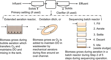
Simplified schematic of unit operations that implement suspended growth aerobic biological treatment
Fig. 7.11 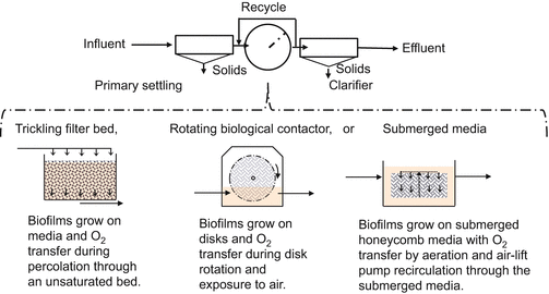
Simplified schematic of unit operations that implement attached growth aerobic biological treatment
-
-
■ Decoupling hydraulic and solid retention times
-
• Water flows through a bioreactor but biomass is retained
-
○ This is fundamental to an activated sludge process
-
-
• Retention of biomass solids can be achieved in several ways
-
○ Through settling of biomass solids in a clarifier following the aeration tank in a suspended growth, flow-through bioreactor (Fig. 7.12)
Fig. 7.12 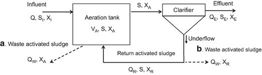
Simplified illustration of a common suspended growth activated sludge system with solids separation by clarification and solids wasting from (a) the aeration tank or (b) from the recycle line from the secondary clarifier
-
○ Through settling of biomass solids during a clarification step in a suspended growth, sequencing batch reactor
-
○ Through attachment of biomass to physical structures placed in the aeration tank such as stones or plastic honeycombs in an attached growth bioreactor
-
○ Through use of a membrane through which biomass solids cannot pass (Membrane Bioreactors are described in Chap. 9)
-
○ Figure 7.12 illustrates a basic activated sludge process where aeration tank biomass solids are separated in a secondary clarifier
-
* Biomass solids are returned to the aeration tank as Return Activated Sludge
-
* Excess biomass solids are removed as waste activated sludge by (a) pumping from the aeration tank or (b) diverting a portion of the underflow of the secondary clarifier
-
-
-
• For the flow regime shown in Fig. 7.12b, the hydraulic retention time (HRT) and the solids retention time (SRT) are given by Eqs. 7.14 and 7.15
$$ \mathrm{H}\mathrm{R}\mathrm{T}=\frac{{\mathrm{V}}_{\mathrm{A}}}{{\mathrm{Q}}_{\mathrm{D}}} $$(7.14)$$ \mathrm{S}\mathrm{R}\mathrm{T}=\frac{{\mathrm{V}}_{\mathrm{A}}{\mathrm{X}}_{\mathrm{A}}}{{\mathrm{Q}}_{\mathrm{W}}{\mathrm{X}}_{\mathrm{W}}+{\mathrm{Q}}_{\mathrm{E}}{\mathrm{X}}_{\mathrm{E}}}\approx \frac{{\mathrm{V}}_{\mathrm{A}}{\mathrm{X}}_{\mathrm{A}}}{{\mathrm{Q}}_{\mathrm{W}}{\mathrm{X}}_{\mathrm{W}}} $$(7.15)Where:
-
HRT = hydraulic retention time (day)
-
SRT = solids retention time (day)
-
VA = aeration tank volume (gal)
-
QD = design daily flow rate (gal/day) (e.g., QA × PF)
-
QW = daily flow rate of waste solids (gal/day)
-
QE = daily effluent flow rate (gal/day)
-
XA = concentration of VSS in the aeration tank (mg-VSS/L)
-
XW = concentration of VSS in the waste activated sludge (mg-VSS/L)
-
XE = concentration of VSS in the effluent (mg-VSS/L) (assumed negligible compared to XA or XW
-
-
-
■ Mass balances on cells and substrate in the bioreactor
-
• Mass balances are used to formulate expressions for cell growth and substrate utilization (e.g., Eq. 7.16 based on Fig. 7.12b)
Accumulation = inflow—outflow + net growth
$$ \frac{\mathrm{dX}}{\mathrm{dt}}{\mathrm{V}}_{\mathrm{A}}={\mathrm{Q}\mathrm{X}}_{\mathrm{I}}-\left({\mathrm{Q}}_{\mathrm{W}}{\mathrm{X}}_{\mathrm{R}}+{\mathrm{Q}}_{\mathrm{E}}{\mathrm{X}}_{\mathrm{E}}\right)+{\mathrm{V}}_{\mathrm{A}}{\mathrm{r}}_g^{\prime } $$(7.16)Where:
-
dX/dt = rate of change of cells in the bioreactor (mg-VSS/L per day)
-
VA = volume of aeration unit (gal)
-
Q = influent flow rate (gal/day)
-
QW = wasting flow rate (gal/day)
-
QE = effluent flow rate (gal/day)
-
XI = influent concentration of cells (mg-VSS/L)
-
XR = concentration of cells in the recycle line (mg-VSS/L)
-
XE = concentration of cells in the effluent (mg-VSS/L)
-
rg′ = net rate of growth of cells (mg-VSS/L per day)
-
-
-
■ Solids generation, retention and wasting
-
• Cells are generated as substrate is utilized for growth
-
• The net generation rate depends on the rate of cell growth, the SRT and the endogenous decay rate
-
○ The rates are temperature dependent, generally increasing with increasing temperature
-
-
• In an activated sludge process, there is a need for wasting of excess cells and other organic and inorganic solids that become associated with them during clarification
-
○ Assuming cells in the effluent are much lower than cells in the aeration tank, at steady-state the net rate of cell mass growth equals the rate of cell mass solids being wasted (Eq. 7.17)
-
○ The net rate of growth for a given MLVSS in an aeration tank is equal to the inverse of the SRT (Eq. 7.18)
$$ {\mathrm{r}}_{\mathrm{g}}\hbox{'}{\mathrm{V}}_{\mathrm{A}}\approx {\mathrm{Q}}_{\mathrm{W}}{\mathrm{X}}_{\mathrm{W}}\Rightarrow \frac{{\mathrm{r}}_{\mathrm{g}}\hbox{'}{\mathrm{V}}_{\mathrm{A}}}{{\mathrm{X}}_{\mathrm{A}}}\approx \frac{{\mathrm{Q}}_{\mathrm{W}}{\mathrm{X}}_{\mathrm{W}}}{{\mathrm{X}}_{\mathrm{A}}} $$(7.17)$$ \frac{{\mathrm{r}}_{\mathrm{g}}\hbox{'}}{{\mathrm{X}}_{\mathrm{A}}}\approx \frac{{\mathrm{Q}}_{\mathrm{W}}{\mathrm{X}}_{\mathrm{W}}}{{\mathrm{X}}_{\mathrm{A}}{\mathrm{V}}_{\mathrm{A}}}\approx \frac{1}{\mathrm{SRT}} $$(7.18)Where:
-
rg′ = net rate of bacterial growth (mgVSS/L per day)
-
VA = aeration tank volume (gal)
-
QW = daily flow rate of waste solids (gal/day)
-
XA = concentration of cells in the aeration tank (mgVSS/L)
-
XW = concentration of cells in the wasted solids (mgVSS/L)
-
SRT = solids retention time (day)
-
-
-
• Wasting of activated sludge solids
-
○ In a suspended growth process, solids can be wasted by:
-
○ In an attached growth process, solids can be wasted by:
-
* Sloughing of solids from media supporting attached growth followed by clarification
-
-
○ Important to solids separation by clarification, the conditions under which cell growth occurs can influence the character of the activated sludge with respect to its settleability
-
* Settleability is critical to achieving activated sludge separation from liquid wastewater, which is often accomplished using a clarification process (Fig. 7.12)
-
-
○ Activated sludge solids that are wasted need to be properly treated for disposal or beneficial recovery (see Chap. 15)
-
-
-
■ Biological nutrient removal


7.1.1.4 7-4. Design and Implementation
-
■ Considerations for design and implementation (D&I) of aerobic bioreactors to achieve secondary treatment and nitrification
-
• Source of wastewater to be treated
-
• Bioreactor configurations and specific D&I options
-
○ Design of suspended growth bioreactors (SGB)
-
* Design parameters
-
* Bioreactor volume, biomass solids separation and retention, solids production and wasting, oxygen and energy needs
-
-
○ Design of attached growth bioreactors (AGB)
-
* Design parameters
-
* Bioreactor volume, other considerations
-
-
-
• System installation and startup at the site
-
• System operation and maintenance (O&M) requirements
-
• Appurtenances and integral treatment operations
-
-
■ D&I considerations—Wastewater source
-
• Aerobic treatment can be used for wastewaters of widely different characteristics
-
○ Wastewaters from residential and nonresidential buildings and developments, especially where BOD concentrations are high
-
○ Buildings and developments should have relatively continuous and consistent day-to-day wastewater flow and composition
-
-
• Pretreatment requirements
-
○ Primary treatment can be beneficial
-
○ Flow equalization can be important and can be accomplished in:
-
* A septic tank or first compartment of the bioreactor system
-
* An equalization tank upstream of the bioreactor
-
-
○ Consideration needs to be given to water quality issues
-
* Toxic substances can inhibit or disrupt bioprocesses (e.g., quaternary ammonium salts, zinc)
-
* Alkalinity additions may be needed to support nitrification
-
-
-
-
■ D&I considerations—Bioreactor configurations
-
• There are numerous bioreactor configurations that have different biomass and flow regime characteristics to achieve similar or different treatment goals
-
• For example, for many decentralized applications the following configurations are common
-
○ Flow-through completely mixed, suspended or attached growth bioreactors with extended aeration
-
* Extended aeration (suspended growth)
-
* Submerged media or trickling filters (attached growth)
-
-
○ Flow-through pseudo plug flow or batch systems, with suspended growth and sequential zones of aeration and no aeration to help achieve nutrient removal
-
* Oxidation ditch (suspended growth)
-
* Sequencing batch reactor (suspended growth)
-
-
-
• Examples of bioreactor configurations that are often used in decentralized applications are summarized in Tables 7.5 and 7.6
Table 7.5 Features of aerobic treatment operations involving suspended growth processes a Table 7.6 Features of aerobic treatment operations involving attached growth processes a -
• Design and implementation options for bioreactor configurations
-
○ Pre-manufactured, off-the-shelf commercial units
-
* Selected based on source features (flow and composition)
-
* For larger residential systems and non-residential sources, some engineering may be required to select the correct unit (often referred to as “package plants”)
-
-
○ Engineered and site-specific construction
-
* For larger flows (e.g., large commercial or institutional sources, mixed-use developments, etc.)
-
* Mix of pre-manufactured components plus site-fabricated tankage and equipment etc.
-
-
-
• In the following pages several considerations specific to common suspended and attached growth processes are given to illustrate how design and implementation can be accomplished
-
-
■ D&I considerations for a SGB—Design parameters
-
• Design of a suspended growth bioreactor
-
○ Design includes determining the aeration tank volume, clarifier sizing, solids generation and sludge wasting, DO requirements, and so forth
-
○ Design parameters are based on biological treatment processes and principles, but specific values are often based on experience with field operations
-
-
• Tables 7.7 and 7.8 list key design parameters for two configurations often used for decentralized applications
Table 7.7 Design parameters for ATU s using suspended growth extended aeration (after USEPA 2002) Table 7.8 Design parameters for ATUs using suspended growth sequencing batch reactors (after USEPA 2002) -
○ Extended aeration bioreactors
-
○ Sequencing batch bioreactors
-
-
• The following sections illustrate how the parameters shown in Table 7.7 can be used for design of an extended aeration unit such as illustrated in Fig. 7.13
Fig. 7.13 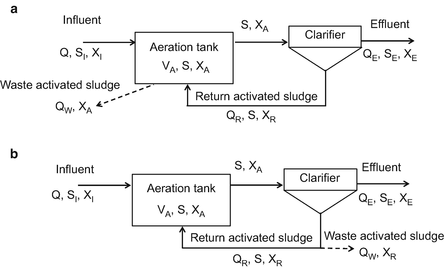
Examples of a common suspended growth activated sludge process with solids separation by clarification and solids wasting from (a) the aeration tank or (b) from a recycle line
-
-
■ D&I considerations for a SGB—Solids production
-
• Net solids production (YN) is a design and operation parameter that takes into account the wastewater characteristics, the chosen SRT, and temperature
-
○ Example values of YN are provided in Table 7.9
Table 7.9 Net solids production, YN (lb-VSS/lb-BOD removed)a, in an aerobic treatment system as affected by wastewater characteristics, solids retention time and temperature
-
-
• In general, YN is higher with a lower quality influent and a shorter SRT under lower temperature conditions, e.g.:
-
○ Lower quality influent (e.g., without primary treatment compared to an influent after primary treatment)
-
* YN ≈ 1.4× to 1.8× higher
-
-
○ Shorter solids retention time (e.g., 5 vs. 30 days)
-
* YN ≈ 1.4× to 1.6× higher
-
-
○ Lower temperatures (e.g. 10 °C vs. 30 °C)
-
* YN ≈ 1.2× to 1.4× higher
-
-
-
• The net solids production that needs to be wasted can be calculated using Eq. 7.19
-
○ Example solids production values are given in Table 7.10
Table 7.10 Calculated net solids produced (lb-VSS/mon) during removal of 100 mg/L of BOD5 from a daily flow rate of 1000 gal/daya $$ {\mathrm{P}}_{\mathrm{X}}={\mathrm{Y}}_{\mathrm{N}}\left[\mathrm{Q}\left({\mathrm{S}}_{\mathrm{I}}-{\mathrm{S}}_{\mathrm{E}}\right)\right]\mathrm{F} $$(7.19)Where:
-
PX = waste activated sludge solids that needs to be wasted (lb/day)
-
YN = net solids production (lb-VSS/lb-BOD removed) as a function of SRT (see Table 7.9)
-
Q = average daily flow rate (gal/day) (Note: this could be the design daily flow rate or the actual daily flow rate being processed)
-
SI = influent BOD concentration (mg/L)
-
SE = effluent BOD concentration (mg/L)
-
F = 8.34 × 10−6 = conversion factor for mg/L to lb/gal
-
-
-
-
■ D&I considerations for a SGB—Aeration tank sizing
-
• The volume of the aeration tank can be determined based on a chosen design SRT using Eq. 7.20
$$ {\mathrm{V}}_{\mathrm{A}}=\frac{\left(\mathrm{S}\mathrm{R}\mathrm{T}\right)\left({\mathrm{Q}}_{\mathrm{D}}\right)\left({\mathrm{S}}_{\mathrm{I}}\right)\left({\mathrm{Y}}_{\mathrm{N}}\right)}{{\mathrm{X}}_{\mathrm{A}}} $$(7.20)Where:
-
VA = volume of the aeration tank (gal)
-
SRT = design solids retention time (days)
-
QD = design average daily flow rate (gal/day)
-
SI = influent BOD or COD substrate concentration (mg/L)
-
YN = net yield coefficient (lb-VSS produced per lb-BOD or COD removed) as a function of SRT (−)
-
XA = average mixed liquor volatile suspended solids (MLVSS) (mg/L)
Note: MLVSS ≈ a fraction of mixed liquor total suspended solids
-
-
• With VA determined, the HRT is given by Eqs. 7.14 or 7.21
$$ \mathrm{H}\mathrm{R}\mathrm{T}=\frac{{\mathrm{V}}_{\mathrm{A}}}{{\mathrm{Q}}_{\mathrm{D}}} $$(7.14)$$ \mathrm{H}\mathrm{R}\mathrm{T}=\frac{\left(\mathrm{S}\mathrm{R}\mathrm{T}\right)\left({\mathrm{S}}_{\mathrm{I}}\right)\left({\mathrm{Y}}_{\mathrm{N}}\right)}{\left({\mathrm{X}}_{\mathrm{A}}\right)} $$(7.21)Where:
-
HRT = hydraulic retention time (day)
-
VA = aeration tank volume (gal)
-
QD = design daily flow rate (gal/day)
-
SRT = solids retention time (day)
-
SI = influent BOD or COD (mg/L)
-
YN = net solids production rate (lb-VSS/lb-BOD or lb-COD removed)
-
XA = average MLVSS concentration (mg-VSS/L)
-
-
-
■ D&I considerations for a SGB—F/M ratio
-
• The food to microorganism ratio (F/M) has been used as a design and operational parameter for activated sludge systems and is calculated using Eq. 7.22
$$ \mathrm{F}\;/\;\mathrm{M}=\frac{{\mathrm{Q}}_{\mathrm{D}}{\mathrm{S}}_{\mathrm{I}}}{{\mathrm{X}}_{\mathrm{A}}{\mathrm{V}}_{\mathrm{A}}} $$(7.22)Where:
-
F/M = food to microorganism ratio (lb-BOD or -COD/day per lb-MLVSS)
-
VA = aeration tank volume (gal)
-
QD = design daily flow (gal/day) (e.g., QA × PF)
-
SI = influent substrate concentration—BOD or COD (mg/L)
-
XA = average mixed liquor volatile suspended solids (MLVSS) (mg/L)
-
-
-
■ D&I considerations—Operating parameter interactions
-
• Parameters are inter-related and can’t be set independently
-
○ Equations 7.21 and 7.23 reveal the relationships for SRT, YN, MLVSS, HRT and F/M
$$ \mathrm{H}\mathrm{R}\mathrm{T}=\frac{\left(\mathrm{S}\mathrm{R}\mathrm{T}\right)\left({\mathrm{S}}_{\mathrm{I}}\right)\left({\mathrm{Y}}_{\mathrm{N}}\right)}{\left({\mathrm{X}}_{\mathrm{A}}\right)} $$(7.21)$$ \mathrm{F}/\mathrm{M}=\frac{\left({\mathrm{Q}}_{\mathrm{D}}\right)\left({\mathrm{S}}_{\mathrm{I}}\right)}{\left({\mathrm{X}}_{\mathrm{A}}\right)\left({\mathrm{V}}_{\mathrm{A}}\right)}=\frac{\left({\mathrm{Q}}_{\mathrm{D}}\right)\left({\mathrm{S}}_{\mathrm{I}}\right)}{\left({\mathrm{X}}_{\mathrm{A}}\right)\left(\mathrm{H}\mathrm{R}\mathrm{T}\right)\left({\mathrm{Q}}_{\mathrm{D}}\right)}=\frac{\left({\mathrm{S}}_{\mathrm{I}}\right)}{\left({\mathrm{X}}_{\mathrm{A}}\right)\left(\mathrm{H}\mathrm{R}\mathrm{T}\right)} $$(7.23)
-
-
• Table 7.11 shows calculation results using Eqs. 7.21 and 7.23 for treatment of primary effluent at 20 °C and reveals:
Table 7.11 Example parameter values for extended aeration under varied conditions -
○ As the SRT increases, YN decreases (and vice versa)
-
○ For the same SRT, as the XA increases the HRT decreases (and vice versa) and F/M stays the same
-
-
-
■ D&I considerations for a SGB—Solids recycling
-
• Activated sludge solids must be retained in the aeration tank
-
○ A mass balance on the aeration tank with XI assumed negligible is given by Eq. 7.24, which can be rearranged as Eq. 7.25
$$ {\mathrm{Q}}_{\mathrm{R}}\left({\mathrm{X}}_{\mathrm{R}}\right)=\left(\mathrm{Q}+{\mathrm{Q}}_{\mathrm{R}}\right){\mathrm{X}}_{\mathrm{A}} $$(7.24)$$ \mathrm{R}\approx \frac{{\mathrm{Q}}_{\mathrm{R}}}{\mathrm{Q}}\approx \frac{{\mathrm{X}}_{\mathrm{A}}}{{\mathrm{X}}_{\mathrm{R}}-{\mathrm{X}}_{\mathrm{A}}} $$(7.25)Where:
-
Q = influent daily flow rate (gal/day)
-
QR = recycle flow rate from a clarifier back to the aeration tank (gal/day)
-
XI = influent VSS or TSS; XI ≪ XA
-
XR = VSS or TSS in the recycle line back to the aeration tank (mg/L)
-
XA = VSS or TSS in the aeration tank (mg/L)
-
R = recycle ratio (−) assuming influent VSS is ≪ aeration tank VSS
-
= 0.5 to 1.5 (typ.) for extended aeration
-
-
-
-
■ D&I consideration for a SGB—Solids wasting
-
• Wasting of the activated sludge solids produced is required to maintain a target SRT and MLVSS level, and a healthy F/M ratio
-
• Wasting from the aeration tank
-
○ SRT is defined by Eq. 7.15
$$ \mathrm{S}\mathrm{R}\mathrm{T}=\frac{{\mathrm{V}}_{\mathrm{A}}{\mathrm{X}}_{\mathrm{A}}}{{\mathrm{Q}}_{\mathrm{W}}{\mathrm{X}}_{\mathrm{W}}+{\mathrm{Q}}_{\mathrm{E}}{\mathrm{X}}_{\mathrm{E}}} $$(7.15) -
○ Equation 7.15 can be rearranged and with XW = XA and XE ≈ 0, QW is given by Eq. 7.26
$$ {\mathrm{Q}}_{\mathrm{W}}=\frac{{\mathrm{V}}_{\mathrm{A}}}{\mathrm{SRT}} $$(7.26)Where,
-
SRT = solids retention time (days)
-
QW = flow rate for solids wasting (gal/day)
-
QE = effluent flow rate (gal/day)
-
VA = volume of the aeration tank (gal)
-
XA = concentration of MLVSS in the aeration tank (mg VSS/L)
-
XW = concentration of MLVSS in the waste solids flow (mg VSS/L)
-
XE = concentration of MLVSS in the effluent (mg VSS/L)
-
-
-
• Wasting from the return line from a clarifier
-
○ A mass balance around the aeration tank in Fig. 7.13b where SI is negligible is given by Eq. 7.24
-
○ Equation 7.24 can be rearranged as Eq. 7.27 and substituting Eq. 7.27 into Eq. 7.15 and rearranging with XR = XW yields Eq. 7.28
$$ {\mathrm{X}}_{\mathrm{A}}=\left(\frac{\mathrm{R}}{1+\mathrm{R}}\right){\mathrm{X}}_{\mathrm{R}} $$(7.27)$$ {\mathrm{Q}}_{\mathrm{W}}=\frac{\left(\frac{\mathrm{R}}{1+\mathrm{R}}\right){\mathrm{V}}_{\mathrm{A}}}{\mathrm{SRT}} $$(7.28)Where,
-
XA = concentration of VSS in the aeration tank (mg/L)
-
R = recycle ratio, QR/Q, (−) (e.g., 0.5–1.5)
-
XR = concentration of VSS in the return line (mg/L)
-
QW = influent flow rate (gal/day)
-
SRT = solids retention time (day)
-
VA = volume of the aeration tank (gal)
-
-
-
• How frequently must solids be wasted?
-
○ This is an important question in the context of aerobic treatment used in a decentralized setting
-
* If you don’t waste excess solids, the SRT and MLVSS increase and the F/M ratio can decline
-
* As a result, solids settleability deteriorates and clarifiers can be overloaded so treatment performance declines
-
-
○ In larger high-rate systems, wasting might be needed daily
-
○ In smaller low-rate systems, including packaged ATUs, wasting is normally done intermittently, e.g., every 3–6 months, by pumping a portion of the mixed liquor out of the aeration tank
-
* This will result in the MLVSS varying around an average value over the duration of an average SRT
-
-
○ It is noted that wasting needs can be estimated but they are often determined by operational monitoring and control (e.g., MLVSS level, solids character and settleabilty, effluent quality)
-
-
• Example of intermittent solids wasting from a low-rate extended aeration treatment unit
-
○ To treat Q = 1000 gal/day with a BOD5 of 150 mg/L to yield an effluent BOD5 = 30 mg/L assuming:
-
* Target SRT = 180 day, average MLVSS is 3000 mg-VSS/L
-
* Primary treatment and the temperature = 20°C with YN = 0.10 lb-VSS/lb-BOD5 removed
-
-
○ According to Eq. 7.20, the aeration tank volume, VA = 900 gal
-
○ For daily wasting to maintain the SRT and MLVSS relatively constant, Eq. 7.26 yields QW = 5 gal/day
-
○ According to Eq. 7.19, removal of 120 mg/L of BOD5 produces 18 lb of VSS during 180 days of operation
-
○ This 18 lb could raise the concentration of VSS in the 900-gal aeration tank by 2400 mg-VSS/L during 180 days of operation
-
○ If solids are wasted from the aeration tank every 180 days (same as the target SRT), about 57 % of the aeration tank volume would need to be removed to keep the MLVSS in a range around the average of 3000 mg-VSS/L
-
* The MLVSS would range from about 4200 down to 1800 mg-VSS/L) as shown in Fig. 7.14
Fig. 7.14 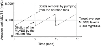
Illustration of MLVSS varying around an average value of 3000 mg/L and SRT of 180 days due to intermittent wasting of solids from the aeration tank only every 180 days.
Note: the aeration tank volume is 900 gal and to remove the 18 lb of excess solids about 514 gal (57 % of VA) of mixed liquor at 4200 mg-VSS/L is pumped out every 180 days.
-
-
-
-
■ D&I considerations for a SGB—Solids separation
-
• Solids produced in the aeration tank are separated from the liquid, normally by settling in a chamber or secondary clarifier
-
○ Under quiescent conditions, cells in a state of endogenous decay can form polymers that aid flocculation and settling under gravity
-
○ Nonvolatile suspended solids can get caught up in the flocs that form and can be removed by settling
-
○ With continued settling the flocs undergo compaction
-
-
• Settleability (including compactibility) are affected by the SRT and F/M ratio
-
○ At low SRTs, activated sludge solids can be populated by filamentous organisms that inhibit flocculation and lead to poor settleability
-
○ At very long SRTs with low F/M, flocculation can be inhibited and pinpoint flocs can form that do not settle very well
-
-
• Sludge settleability as assessed using the sludge volume index
-
○ The sludge volume index (SVI) is a simple test to assess solids settleability but not theoretically based
-
* The SVI test procedure is simple and easily done
-
– After 30 min. the volume of settled solids in a 1-L conical cylinder can be used to calculate the SVI (Eq. 7.29)
$$ \mathrm{S}\mathrm{V}\mathrm{I}=\frac{\mathrm{settled}\ \mathrm{solids}\ \mathrm{volume}\ \left(\mathrm{mL}\kern0.1em /\kern0.1em \mathrm{L}\right)\left(1000\;\mathrm{mg}\kern0.1em /\kern0.1em \mathrm{g}\right)}{\mathrm{suspended}\ \mathrm{solids}\ \left(\mathrm{mg}\kern0.1em /\kern0.1em \mathrm{L}\right)}=\frac{\mathrm{mL}}{\mathrm{g}} $$(7.29)
-
-
-
○ Activated sludge with SVI values in the range of 50–150 mL/g is typically considered to have good settling characteristics
-
○ Sludge settleability varies as a function of operating conditions such as the SRT or F/M
-
* The effects on settleability can be reflected in the SVI as shown in Fig. 7.15
Fig. 7.15 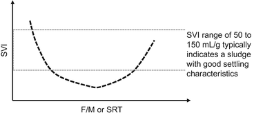
Illustration of sludge settleabilty as measured by the SVI revealing the effects of F/M or SRT
-
-
○ If it assumed that conditions in a clarifier are the same as in the lab SVI test, Eq. 7.30 can be used to estimate XR (for XR <10,000 mg/L)
$$ {\mathrm{X}}_{\mathrm{R}}\approx \frac{\left({10}^3\mathrm{mL}\kern0.1em /\kern0.1em \mathrm{L}\right)\left({10}^3\mathrm{mg}\kern0.1em /\kern0.1em \mathrm{g}\right)}{\mathrm{SVI}\kern0.5em \mathrm{mL}\kern0.1em /\kern0.1em \mathrm{g}}=\frac{\mathrm{mg}}{\mathrm{L}} $$(7.30)
-
-
• Sludge settleability assessed by zone settling rates
-
○ Assessing sludge settleability using zone settling rates is more technically sound than the SVI but this requires more complicated testing
-
* If the zone settling rate (Vi) is measured during a lab test it can be used to determine the overflow rate for design purposes (Eqs. 7.31 and 7.32)
$$ {\mathrm{OR}}_{\mathrm{D}}=\frac{\left({\mathrm{V}}_{\mathrm{i}}\right)(179.5)}{\mathrm{SF}} $$(7.31)$$ {\mathrm{V}}_{\mathrm{i}}={\mathrm{V}}_{\max } \exp \left(\left(-\mathrm{K}\kern0.5em \times \kern0.5em {10}^{-6}\right){\mathrm{X}}_{\mathrm{A}}\right) $$(7.32)Where:
-
ORD = design surface overflow rate (gal/ft2/day)
-
Vi = estimated settling velocity of the solids interface (ft/h)
-
179.5 = conversion factor from ft/h to gal/ft2-day [(24 h/day)(748 gal/ft3)]
-
SF = safety factor for nonideal conditions in clarifiers (typ. 1.75–2.5)
-
Vmax = maximum settling velocity of the interface (typ. 23 ft/h)
-
K = constant (e.g., around 600 L/mg)
-
XA = average mixed liquor suspended solids (mg/L)
-
-
-
-
• Design of secondary clarifiers
-
○ Clarifiers need to be designed to achieve suitable surface overflow rates (OR) and solids loading rates (SLR) to avoid carryover of solids into the effluent
-
○ A secondary clarifier is illustrated in Fig. 7.16
Fig. 7.16 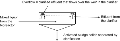
Cross-section of a secondary clarifier used for activated sludge solids separation and return
-
○ The OR and SLR are calculated as shown in Eqs. 7.33 and 7.34
$$ {\mathrm{A}}_{\mathrm{c}}=\frac{{\mathrm{Q}}_{\mathrm{D}}}{{\mathrm{OR}}_{\mathrm{D}}} $$(7.33)$$ \mathrm{S}\mathrm{L}\mathrm{R}=\frac{\left(1+\mathrm{R}\right)\left({\mathrm{Q}}_{\mathrm{D}}\right)\left({\mathrm{X}}_{\mathrm{A}}\right)\left(\mathrm{F}\right)}{{\mathrm{A}}_{\mathrm{c}}} $$(7.34)Where:
-
Ac = surface area of the clarifier (ft2)
-
QD = design flow rate into the clarifier (gal/day)
-
R = recycle ratio for activated sludge return (−)
-
ORD = design surface overflow rate (gal/day/ft2) (Eq. 7.31)
-
SLR = solids loading rate (lb-TSS/ft2/h)
-
XA = average mixed liquor suspended solids (mg/L)
-
F = 0.35 × 10−6 = conversion factor for mg/L to lb/gal and hour to days
-
-
○ Experience-based values for OR and SLR
-
* Typical OR (gal/day/ft2) to clarify effluents from different aerobic unit designs are presented in Table 7.13
Table 7.13 Experienced-based values for clarifier OR and SLR values -
* If SLR values get too high, solids will wash out of the clarifier and the effluent quality will deteriorate
-
-
-
-
■ D&I considerations for SGB—Oxygen requirements
-
• For advanced secondary treatment, oxygen is required for organic matter degradation and nitrification as given by Eq. 7.35
$$ {\mathrm{O}}_2\mathrm{R}=\left[\frac{\mathrm{Q}\left({\mathrm{S}}_{\mathrm{I}}-{\mathrm{S}}_{\mathrm{E}}\right)}{\mathrm{f}}-1.42\left({\mathrm{Q}}_{\mathrm{W}}{\mathrm{X}}_{\mathrm{W}}\right)+4.57\mathrm{Q}\left({\mathrm{N}}_{\mathrm{I}}-{\mathrm{N}}_{\mathrm{E}}\right)\right]\mathrm{F} $$(7.35)Where:
-
O2R = total oxygen requirement (lb-O2/day)
-
Q = average daily flow rate (gal/day)
-
SI = influent BOD5 concentration (mg/L)
-
SE = effluent BOD5 concentration (mg/L)
-
f = ratio of BOD5 to ultimate BOD (−) (e.g., 0.70)
-
QW = waste flow rate (gal/day)
-
XW = concentration of solids in the waste activated sludge (mgVSS/L)
-
NI = influent TKN concentration (mg-N/L)
-
NE = effluent TKN concentration (mg-N/L)
-
F = 8.34 × 10−6 = conversion factor for mg/L to lb/gal
-
-
• Experience-based oxygen requirements for several activated sludge processes are highlighted in Table 7.14
Table 7.14 Typical oxygen requirements to support activated sludge biological treatment (Crites and Tchobanoglous 1998) -
• Methods of adding DO to wastewater
-
○ Mechanical aeration devices that mix air into wastewater
-
* O2 transfer into the wastewater depends on the aerator type and size
-
– Transfer rates can range from 1.5 to 2.5 lb-O2 per hp-h.
-
-
-
○ Diffusers which inject air into wastewater being aerated
-
* O2 transfer depends on the diffuser type (fine bubble vs. coarse bubble) and activated sludge process
-
– Oxygen transfer rates typically can range from 4 to 16 % of the O2 injected
-
– High purity oxygen can be used instead of air to increase the DO in the wastewater
-
-
-
○ Both methods require power for motors, pumps, mixers, and/or compressors
-
-
-
■ D&I considerations for a SGB—Energy requirements
-
• Aerobic biological treatment operations normally require power
-
• One major area of power consumption is for mixing
-
○ Mixing needs to keep the biomass suspended in an aeration tank, basin, channel, etc.
-
○ Mixing needs to bring the wastewater into contact with attached growth biomass
-
-
• Mixing can be achieved during aeration by mechanical aerators or diffusers
-
• Example requirements for mixing are illustrated in Table 7.15
Table 7.15 Input requirements for mixing during activated sludge biological treatment
-
-
■ D&I considerations for an AGB—Design parameters
-
○ Design of an ATU that utilizes an attached growth bioreactor
-
* Design includes determining the bioreactor volume, biomass solids retention and return, sludge wasting, and so forth
-
* Design parameters are based on biological treatment processes and principles, but specific values are often based on experience with field operations
-
-
○ Tables 7.16 and 7.17 list key design parameters for two configurations often used for decentralized applications
Table 7.16 Design parameters for ATUs using attached growth trickling filters and rotating biological contactors (after USEPA 2002) Table 7.17 Design parameters for ATUs using attached growth trickling filters (Crites and Tchobanoglous 1998) -
* Trickling filters
-
* Rotating biological contactors
-
-
○ The following sections illustrate how the design parameters can be used for design of a trickling filter
-
-
■ D&I considerations for an AGB—Bioreactor sizing
-
• A variety of attached growth system designs are used including trickling filters and rotating biological contactors
-
• Sizing of the bioreactor for attached growth systems is more empirical than sizing of suspended growth aeration designs
-
○ For example, for low-rate trickling filters using rock media (Fig. 7.17) typical design parameters are:
Fig. 7.17 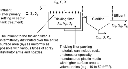
Illustration of a trickling filter used for aerobic biological treatment
-
* Media diameter = 1 to 5 in.
-
* Depth of filter medium (DF) = 6 to 8 ft
-
* Hydraulic loading rate (HLR) = 23 to 92 gal/day/ft2
-
* Recirculation ratio = 0 to 1
-
* Organic loading rate (OLR) = 5 to 25 lb-BOD5/day per 1000 ft3 of filter volume for BOD removal and 5 to 10 lb-BOD5/day per 1000 ft3 for nitrification
-
-
-
• Simplified sizing equations for a trickling filter are given in Eqs. 7.36, 7.37 and 7.38
$$ {\mathrm{A}}_{\mathrm{F}}=\frac{{\mathrm{Q}}_{\mathrm{D}}}{\mathrm{HLR}} $$(7.36)$$ {\mathrm{V}}_{\mathrm{F}}=\frac{\left({\mathrm{Q}}_{\mathrm{D}}\right)\left({\mathrm{BOD}}_5\right)\left(\mathrm{F}\right)}{\mathrm{OLR}} $$(7.37)$$ {\mathrm{D}}_{\mathrm{F}}=\frac{{\mathrm{V}}_{\mathrm{F}}}{{\mathrm{A}}_{\mathrm{F}}} $$(7.38)Where:
-
AF = trickling filter surface area (ft2)
-
VF = volume of the trickling filter (ft3)
-
DF = depth of the filter medium (ft)
-
QD = design daily flow (gal/day)
-
BOD5 = influent concentration of BOD5 (mg/L)
-
HLR = hydraulic loading rate applied to the filter surface area (gal/day/ft2)
-
OLR = organic loading rate applied to the filter volume (lb-BOD5/day per ft3)
-
F = 8.34 × 10−6 = conversion factor for mg/L to lb/gal
-
-
-
■ D&I considerations for an AGB—Other considerations
-
• Other D&I considerations are similar to those that apply to aerobic treatment using suspended growth processes, including:
-
○ Biomass generation and removal
-
○ Solids wasting and management
-
○ Oxygen and energy requirements
-
-
• However, there are differences in requirements and parameter values
-
-
■ D&I considerations—Installation and startup
-
• Proper installation is critical to achieving the expected performance of aerobic biological treatment systems
-
○ This is similar to, but even more important than, that for septic tanks (refer to Chap. 6), including:
-
* The location of the aerobic treatment unit must enable access for construction equipment and service vehicles
-
* Tankage and piping needs to be watertight and structurally sound
-
* Materials of construction need to be corrosion resistant
-
* Power is required for pumps, aerators, controls, etc. so power sources need to be robust and reliable
-
-
-
• Proper startup is also critical to performance
-
○ Seeding of the aeration tank with activated sludge from another biological treatment unit can be helpful
-
-
-
■ D&I considerations—Appurtenances and integral treatment processes
-
• Basic appurtenances can be important, if not critical, to successful aerobic biological treatment, including:
-
○ Air compressors, tubing, and diffusers
-
○ Mixers, pumps and controls
-
○ Sensors, data recorders, alarms
-
-
• There can also be integral treatment processes, for example:
-
○ ATUs can have an integral primary sedimentation chamber to which raw wastewater flows to avoid the need for a separate settling basin or septic tank prior to the bioreactor
-
○ Some commercial ATUs also have integral disinfection unit operations, which can enable surface discharge and reuse of effluent
-
-
-
■ D&I considerations—Operation & maintenance
-
• Proper O&M is critical to achieving performance capabilities
-
• Inspections should be done frequently (e.g., monthly)
-
○ Conditions important to treatment should be observed
-
* Power and controls need to be online and functional
-
* Pumps and valves need to be properly functioning
-
* Aeration equipment needs to be operational
-
* Distributors and nozzles for attached growth systems such as trickling filters need to be clear and functioning
-
* DO levels must be adequate (typ. >2 mg/L)
-
* Mixed liquor should be settleable (e.g., SV = 50–150 mg/L)
-
-
-
• Effluent quality monitoring may be needed for process control and compliance
-
• Excess solids should be removed and wasted as needed
-
• Certain problems leading to O&M needs can occur when aerobic treatment units are used in decentralized applications
-
○ Suspended growth processes
-
* Problems with maintaining adequate aeration and mixing and good settling characteristics for the activated sludge solids
-
-
○ Attached growth processes
-
* Problems with pumping and distribution of wastewater over the media that biomass is attached to without causing sloughing
-
-
-
• In general, aerobic treatment operations serving larger flows (e.g., clusters of houses or businesses) tend to perform better than those serving individual houses because:
-
○ The influent flow and composition tends to be relatively continuous and consistent over time
-
○ Based on size and economies of scale, the necessary routine O&M needs can be assured
-
-


7.1.1.5 7-5. Summary
-
■ Aerobic biological treatment processes are involved in many unit operations used in decentralized systems
-
■ Aerobic treatment units can be designed where the biomass is suspended or attached to surfaces in different types of bioreactors
-
• Extended aeration systems with long SRTs are most often used to minimize excess solids production and enable infrequent wasting of solids
-
-
■ Aerobic treatment units can produce advanced secondary effluents that are very low in BOD5, TSS, and NH4 +
-
■ Aerobic treatment units require a reasonably continuous and consistent influent, conditions favorable to aerobic bioprocesses, and reliable O&M to ensure performance is sustainably achieved
7.1.1.6 7-6. Example Problems
-
■ 7EP-1. Sizing an aeration tank and estimating the solids wasting rate
-
• Given information
-
○ Extended aeration is being used to treat the wastewater from a residential and commercial complex
-
○ Influent characteristics: Design QD = 52,840 gal/day; primary effluent BOD5 = 250 mg/L and TSS = 50 mg/L; average temperature = 20 °C
-
○ Effluent requirements: BOD5 and TSS <20 mg/L
-
○ Aeration tank design parameters are chosen to be SRT = 15 days with MLVSS = 4000 mg/L
-
-
• Determine
-
○ The volume of the aeration tank (gal)
-
○ The hydraulic retention time (HRT) (days)
-
○ The rate of wasting excess solids from the aeration tank (gal/day)
-
-
• Solution
-
○ Determine the volume of the aeration unit based on the given design flow rate and operating conditions using Eq. 7.19
-
* For primary effluent with a temperature = 20 °C, YN = 0.39 lb VSS produced per lb BOD removed (see Table 7.9)
$$ \begin{array}{l}{\mathrm{V}}_{\mathrm{A}}=\frac{\left(\mathrm{S}\mathrm{R}\mathrm{T}\right)\left({\mathrm{Q}}_{\mathrm{D}}\right)\left({\mathrm{S}}_{\mathrm{I}}\right)\left({\mathrm{Y}}_{\mathrm{N}}\right)}{{\mathrm{X}}_{\mathrm{A}}}\\ {}{\mathrm{V}}_{\mathrm{A}}=\frac{\left(15\;\mathrm{days}\right)\left(52,\kern-1pt 840\;\mathrm{gal}/\mathrm{day}\right)\left(250\;\mathrm{mg}/\mathrm{L}\right)\left(0.39\;\mathrm{lb}\hbox{-} \mathrm{V}\mathrm{S}\mathrm{S}/\mathrm{lb}\hbox{-} \mathrm{BOD}\right)}{4000\;\mathrm{mg}\hbox{-} \mathrm{V}\mathrm{S}\mathrm{S}\kern0.1em /\kern0.1em \mathrm{L}}\\ {}{\mathrm{V}}_{\mathrm{A}}=19,\kern-1pt 320\;\mathrm{gal}\end{array} $$(7.20)Note: you could provide the required VA in two 9660 gal tanks operated in parallel.
-
-
○ Determine the hydraulic retention time using Eq. 7.14
$$ \begin{array}{l}\mathrm{H}\mathrm{R}\mathrm{T}=\frac{{\mathrm{V}}_{\mathrm{A}}}{{\mathrm{Q}}_{\mathrm{D}}}\\ {}\mathrm{H}\mathrm{R}\mathrm{T}=\frac{19,\kern-1.5pt 320\;\mathrm{gal}}{52,\kern-1.3pt 840\;\mathrm{gal}\kern0.1em /\kern0.1em \mathrm{day}}=0.36\;\mathrm{day}\mathrm{s}=8.8\;\mathrm{h}.\end{array} $$(7.14) -
○ Determine the rate of solids wasting from the aeration tank using Eq. 7.26
$$ \begin{array}{l}{\mathrm{Q}}_{\mathrm{W}}=\frac{{\mathrm{V}}_{\mathrm{A}}}{\mathrm{SRT}}\\ {}{\mathrm{Q}}_{\mathrm{W}}=\frac{19,\kern-1.5pt 320\kern0.5em \mathrm{gal}}{15\;\mathrm{days}}=1288\frac{\mathrm{gal}}{\mathrm{day}}\end{array} $$(7.26) -
○ You can also estimate the solids wasting rate using Eq. 7.18
-
* Equation 7.18 uses the net rate of cell growth and the target SRT and ignores the contribution due to TSS
$$ \begin{array}{l}\frac{\mathrm{r}{\hbox{'}}_{\mathrm{g}}}{{\mathrm{X}}_{\mathrm{A}}}\approx \frac{{\mathrm{Q}}_{\mathrm{W}}{\mathrm{X}}_{\mathrm{W}}}{{\mathrm{X}}_{\mathrm{A}}{\mathrm{V}}_{\mathrm{A}}}\approx \frac{1}{\mathrm{SRT}}\\ {}\mathrm{r}{\hbox{'}}_{\mathrm{g}}\approx \frac{{\mathrm{X}}_{\mathrm{A}}}{\mathrm{SRT}}\approx \frac{4000\kern0.15em \mathrm{mg}\kern0.1em /\kern0.1em \mathrm{L}}{15\kern0.5em \mathrm{days}}=267\kern0.15em \mathrm{mg}\kern0.1em /\kern0.1em \mathrm{L}/\mathrm{d}\mathrm{ay}\\ {}{\mathrm{Q}}_{\mathrm{W}}=\frac{\mathrm{r}{\hbox{'}}_{\mathrm{g}}{\mathrm{V}}_{\mathrm{A}}}{{\mathrm{X}}_{\mathrm{W}}}=\frac{\left(267\kern0.15em \mathrm{mg}\kern0.1em /\mathrm{L}/\mathrm{d}\right)\left(19,\kern-1.2pt 320\ \mathrm{gal}\right)}{4000\ \mathrm{mg}\kern0.1em /\kern0.1em \mathrm{L}}\\ {}{\mathrm{Q}}_{\mathrm{W}}=1289\;\mathrm{gal}/\mathrm{d}\mathrm{ay}\end{array} $$(7.18)
-
-
-
-
■ 7EP-2. Design of an extended aeration unit
-
• Given information
-
○ Alpine Meadows is a condominium complex (32 units) that needs a new decentralized wastewater system and is considering an extended aeration unit
-
○ Based on monitoring over the past 2 years, QD = 5000 gal/day and after septic tank treatment, the BOD5 = 150 mg/L and TSS = 100 mg/L
-
○ The average daily temperature is about 20 °C
-
-
• Determine
-
○ Choose reasonable values for the SRT and XA and determine the size of the aeration tank (gal) to handle the design flow
-
○ Check the F/M ratio and the HRT to see if they are reasonable for an extended aeration process
-
-
• Solution
-
○ Determine the volume of the aeration tank based on the given design flow rate and operating conditions using Eq. 7.20
-
* Assuming a SRT = 15 days with average XA = 3000 mg-VSS/L, for primary effluent with a temperature = 20 °C, YN = 0.48 lb-VSS per lb-BOD removed (see Table 7.9)
$$ \begin{array}{l}{\mathrm{V}}_{\mathrm{A}}=\frac{\left(\mathrm{S}\mathrm{R}\mathrm{T}\right)\left({\mathrm{Q}}_{\mathrm{D}}\right)\left({\mathrm{S}}_{\mathrm{I}}\right)\left({\mathrm{Y}}_{\mathrm{N}}\right)}{{\mathrm{X}}_{\mathrm{A}}}\\ {}{\mathrm{V}}_{\mathrm{A}}=\frac{\left(15\;\mathrm{day}\mathrm{s}\right)\left(5000\;\mathrm{gal}\kern0.1em /\kern0.1em \mathrm{day}\right)\left(150\;\mathrm{mg}\kern0.1em /\kern0.1em \mathrm{L}\right)\left(0.48\;\mathrm{lb}\hbox{-} \mathrm{V}\mathrm{S}\mathrm{S}/\mathrm{lb}\;\hbox{-} \mathrm{BOD}\right)}{3000\;\mathrm{mg}\hbox{-} \mathrm{V}\mathrm{S}\mathrm{S}\kern0.1em /\kern0.1em \mathrm{L}}\\ {}{\mathrm{V}}_{\mathrm{A}}=1800\;\mathrm{gal}\end{array} $$(7.20)
-
-
○ Check the F/M ratio and HRT
$$ \begin{array}{l}\mathrm{F}/\mathrm{M}=\frac{{\mathrm{Q}}_{\mathrm{D}}{\mathrm{S}}_{\mathrm{I}}}{{\mathrm{X}}_{\mathrm{A}}{\mathrm{V}}_{\mathrm{A}}}\\ {}\mathrm{F}/\mathrm{M}=\frac{\left(5000\;\mathrm{gal}\kern0.1em /\kern0.1em \mathrm{day}\right)\left(150\;\mathrm{mg}\;\mathrm{BOD}\kern0.1em /\kern0.1em \mathrm{L}\right)}{\left(3000\;\mathrm{mg}\;\mathrm{V}\mathrm{S}\mathrm{S}\kern0.1em /\kern0.1em \mathrm{L}\right)\left(1800\;\mathrm{gal}\right)}\\ {}\mathrm{F}/\mathrm{M}=0.139\kern0.5em {\mathrm{day}}^{-1}\end{array} $$(7.22)$$ \begin{array}{l}\mathrm{H}\mathrm{R}\mathrm{T}=\frac{{\mathrm{V}}_{\mathrm{A}}}{{\mathrm{Q}}_{\mathrm{D}}}\\ {}\mathrm{H}\mathrm{R}\mathrm{T}=\frac{1800\kern0.5em \mathrm{gal}}{\left(5000\kern0.5em \mathrm{gal}\kern0.1em /\kern0.1em \mathrm{d}\right)}=0.36\kern0.5em \mathrm{d}\mathrm{ays}=8.6\kern0.5em \mathrm{h}.\end{array} $$(7.14)-
* The F/M ratio is high, but within the range of experienced-based values used for extended aeration (e.g., 0.05–0.15 day−1).
-
* The HRT is relatively short but still in the range of experienced-based values for extended aeration (e.g., 8–36 h).
-
-
-
-
■ 7EP-3. Design of an aeration basin
-
• Given information
-
○ Western Terrace (WT) is a small commercial development outside Denver, CO that is planning to upgrade an existing wastewater facility and considering conversion to an aerobic treatment system
-
○ There is an existing basin that is 10 ft wide by 30 ft long with a total depth of 10 ft that could be used as an extended aeration basin
-
○ Based on monitoring over the past 2 years, QD = 20,000 gal/day and after primary treatment, the BOD5 = 200 mg/L
-
-
• Determine
-
○ Determine if the HRT the existing basin could provide is sufficient for an extended aeration process with reasonable values for a SRT and XA
-
-
• Solution
-
○ Volume of the basin available for use as aeration tank
$$ \begin{array}{l}{\mathrm{V}}_{\mathrm{A}}=\mathrm{L}\times \mathrm{W}\times \mathrm{H}\\ {}{\mathrm{V}}_{\mathrm{A}}=30\;\mathrm{f}\mathrm{t}.\times 10\;\mathrm{f}\mathrm{t}.\times 7\;\mathrm{f}\mathrm{t}.=2100\;\mathrm{f}{\mathrm{t}}^3\\ {}{\mathrm{V}}_{\mathrm{A}}=\left(7.48\;\mathrm{gal}/{\mathrm{ft}}^3\right)\left(2100\;{\mathrm{ft}}^3\right)=15,\kern-1.75pt 708\;\mathrm{gal}\end{array} $$Note: H = 7 ft. to allow 3 ft. as freeboard
-
○ Maximum hydraulic retention time provided by the basin
$$ \begin{array}{l}\mathrm{H}\mathrm{R}\mathrm{T}=\frac{{\mathrm{V}}_{\mathrm{A}}}{{\mathrm{Q}}_{\mathrm{D}}}=\frac{15,\kern-1pt 708\kern0.5em \mathrm{gal}}{\left(20,\kern-1pt 000\;\mathrm{gal}\kern0.1em /\kern0.1em \mathrm{day}\right)}\\ {}\mathrm{H}\mathrm{R}\mathrm{T}=0.78\kern0.5em \mathrm{day}\mathrm{s}=18.8\kern0.5em \mathrm{h}.\end{array} $$(7.14) -
○ HRT that could be used is within the range of experienced-based values for extended aeration (e.g., 8–36 h.)
-
* The SRT can be estimated by trial and error using Eq. 7.21
$$ \begin{array}{l}\mathrm{H}\mathrm{R}\mathrm{T}=\frac{\left(\mathrm{S}\mathrm{R}\mathrm{T}\right)\left({\mathrm{S}}_{\mathrm{I}}\right)\left({\mathrm{Y}}_{\mathrm{N}}\right)}{\left({\mathrm{X}}_{\mathrm{A}}\right)}\\ {}\mathrm{Calculate}\ \mathrm{H}\mathrm{R}\mathrm{T}\ \mathrm{f}\mathrm{o}\mathrm{r}\ \mathrm{a}\ \mathrm{trial}\ \mathrm{S}\mathrm{R}\mathrm{T}=15\;\mathrm{d}\mathrm{a}\mathrm{ys}\ \mathrm{with}\ {\mathrm{Y}}_{\mathrm{N}}=0.48\;\mathrm{lb}\hbox{-} \mathrm{V}\mathrm{S}\mathrm{S}/\mathrm{lb}\hbox{-} \mathrm{BOD}\kern0.5em \\ {}\kern1em \mathrm{a}\mathrm{nd}\ {\mathrm{X}}_{\mathrm{A}}=2000\;\mathrm{mg}\hbox{-} \mathrm{V}\mathrm{S}\mathrm{S}=\mathrm{L}\\ {}\mathrm{H}\mathrm{R}\mathrm{T}=\frac{\left(15\;\mathrm{d}\mathrm{a}\mathrm{ys}\right)\left(150\;\mathrm{mg}\kern0.1em /\kern0.1em \mathrm{L}\right)\left(0.48\;\mathrm{lb}\hbox{-} \mathrm{V}\mathrm{S}\mathrm{S}/\kern0.1em \mathrm{lb}\hbox{-} \mathrm{BOD}\right)}{\left(2000\;\mathrm{mg}\hbox{-} \mathrm{V}\mathrm{S}\mathrm{S}\kern0.1em /\kern0.1em \mathrm{L}\right)}\\ {}\mathrm{H}\mathrm{R}\mathrm{T}=0.54\;\mathrm{d}=13\;\mathrm{h}.\end{array} $$(7.21)
-
-
○ So, choosing a SRT of 15 days and a target XA of 2000 mg-VSS/L results in a required HRT of 13 h, which is lower than the maximum HRT available for the existing basin.
-
-
-
■ 7EP-4. Design of an extended aeration bioreactor to remove organic matter and ammonia nitrogen
-
• Given information
-
○ Influent to the aerobic unit will be primary effluent (Table 7EP.1) with a design flow QD = 7500 gal/day
Table 7EP.1 Composition of the influent to be treated in an extended aeration bioreactor -
○ Design parameters include: SRT = 90 days, XA = 3000 mg-VSS/L, and YN = 0.2 lb-VSS per lb-BOD
-
-
• Determine
-
○ Design an extended aeration unit (w/ solids recycle) to produce a secondary effluent with nitrification
-
-
• Solution
-
○ Calculate the design loadings to the aeration tank
-
* Example calculation using BOD5 from Table 7EP.1 with other calculated values presented in Table 7EP.2
Table 7EP.2 Design loadings in an influent to be treated in an extended aeration bioreactor $$ \begin{array}{l}{\mathrm{BOD}}_5=\left(160\;\mathrm{mg}\kern0.1em /\kern0.1em \mathrm{L}\right)\left(7500\;\mathrm{gal}\kern0.1em /\kern0.1em \mathrm{day}\right)\left(3.785\;\mathrm{L}\kern0.1em /\kern0.1em \mathrm{gal}\right)\left(1\times {10}^{-6}\;\mathrm{kg}\kern0.1em /\kern0.1em \mathrm{mg}\right)\\ {}{\mathrm{BOD}}_5=4.5\;\mathrm{kg}\kern0.1em /\kern0.1em \mathrm{day}=9.92\kern0.5em \mathrm{lb}/\kern0.1em \mathrm{day}\end{array} $$
-
-
○ Determine the volume of the aeration tank
-
* Sizing for a SRT = 90 days
$$ \begin{array}{l}{\mathrm{V}}_{\mathrm{A}}=\frac{\left(\mathrm{S}\mathrm{R}\mathrm{T}\right)\left({\mathrm{Q}}_{\mathrm{D}}\right)\left({\mathrm{S}}_{\mathrm{I}}\right)\left({\mathrm{Y}}_{\mathrm{N}}\right)}{{\mathrm{X}}_{\mathrm{A}}}\\ {}{\mathrm{V}}_{\mathrm{A}}=\frac{\left(90\;\mathrm{day}\right)\left(7500\;\mathrm{gal}/\mathrm{day}\right)\left(160\;\mathrm{mg}/\mathrm{L}\right)\left(0.2\;\mathrm{lb}\hbox{-} \mathrm{V}\mathrm{S}\mathrm{S}/\mathrm{lb}\hbox{-} \mathrm{BOD}\right)}{\left(3000\;\mathrm{mg}\kern-0.25em -\kern-0.25em \mathrm{V}\mathrm{S}\mathrm{S}/\mathrm{L}\right)}=7200\;\mathrm{gal}\end{array} $$(7.20)
-
-
○ Check the F/M using BOD5 = 160 mg/L
$$ \begin{array}{l}\mathrm{F}\kern0.1em /\mathrm{M}=\frac{\left({\mathrm{Q}}_{\mathrm{D}}\right)\left({\mathrm{S}}_{\mathrm{I}}\right)}{{\mathrm{X}}_{\mathrm{A}}{\mathrm{V}}_{\mathrm{A}}}\\ {}\mathrm{F}\kern0.1em /\mathrm{M}=\frac{\left(7500\;\mathrm{gal}/\mathrm{day}\right)\left(160\;\mathrm{mg}\kern0.1em /\kern0.1em \mathrm{L}\right)}{\left(3000\;\mathrm{mg}\hbox{-} \mathrm{V}\mathrm{S}\mathrm{S}\kern0.1em /\kern0.1em \mathrm{L}\right)\left(7200\;\mathrm{gal}\right)}=0.06\;{\mathrm{day}}^{-1}\end{array} $$(7.22)-
* The F/M ratio of 0.06 is okay as it is within the range of experienced-based values used for extended aeration (e.g., 0.05–0.15).
-
-
○ Determine the hydraulic retention time
$$ \mathrm{H}\mathrm{R}\mathrm{T}=\frac{{\mathrm{V}}_{\mathrm{A}}}{{\mathrm{Q}}_{\mathrm{D}}}=\frac{7200\;\mathrm{gal}}{7500\;\mathrm{gal}/\mathrm{day}}=0.96\;\mathrm{day}=23\;\mathrm{h}. $$(7.14)-
* HRT is within the range of experienced-based values for extended aeration (e.g., 8–36 h)
-
-
○ Determine the recycle ratio
-
* Assume the recycle line concentration = 8000 mg-VSS/L and the target XA = 3000 mg-VSS/L
$$ \mathrm{R}=\frac{{\mathrm{X}}_{\mathrm{A}}}{{\mathrm{X}}_{\mathrm{R}}-{\mathrm{X}}_{\mathrm{A}}}=\frac{3000}{8000-3000}=0.6 $$(7.25)-
– The R ratio of 0.6 is okay as it is within the range of experienced-based values used for extended aeration (e.g., 0.5–1.5).
-
-
-
○ Determine the solids production
-
* Solids production can be estimated using Eq. 7.19
$$ \begin{array}{l}{\mathrm{P}}_{\mathrm{X}}={\mathrm{Y}}_{\mathrm{N}}\left[\mathrm{Q}\left({\mathrm{S}}_{\mathrm{I}}-{\mathrm{S}}_{\mathrm{E}}\right)\right]\mathrm{F}\\ {}{\mathrm{P}}_{\mathrm{X}}=0.2\;\mathrm{lb}\kern0.1em /\mathrm{lb}\left[7500\;\mathrm{gal}\kern0.1em /\kern0.1em \mathrm{day}\left(160-20\;\mathrm{mg}\kern0.1em /\kern0.1em \mathrm{L}\right)\right]8.34\times {10}^{-6}\\ {}{\mathrm{P}}_{\mathrm{x}}=1.75\kern0.62em \mathrm{lb}\hbox{-} \mathrm{V}\mathrm{S}\mathrm{S}\kern0.5em \mathrm{per}\kern0.5em \mathrm{day}\end{array} $$(7.19) -
* Solids production can also be estimated using Eq. 7.18
$$ \begin{array}{l}\frac{\mathrm{r}{\hbox{'}}_{\mathrm{g}}}{{\mathrm{X}}_{\mathrm{A}}}\approx \frac{{\mathrm{Q}}_{\mathrm{W}}{\mathrm{X}}_{\mathrm{W}}}{{\mathrm{X}}_{\mathrm{A}}{\mathrm{V}}_{\mathrm{A}}}\approx \frac{1}{\mathrm{SRT}}\\ {}\mathrm{r}{\hbox{'}}_{\mathrm{g}}\approx \frac{{\mathrm{X}}_{\mathrm{A}}}{\mathrm{SRT}}\approx \frac{3000\;\mathrm{mg}\kern0.1em /\kern0.1em \mathrm{L}}{90\;\mathrm{day}}=33.3\;\mathrm{mg}\kern0.1em /\kern0.1em \mathrm{L}/\mathrm{day}\\ {}{\mathrm{P}}_{\mathrm{X}}=\left(33.3\;\mathrm{mg}\kern0.1em /\kern0.1em \mathrm{L}/\mathrm{day}\right)\left(7200\;\mathrm{gal}\right)\left(3.785\;\mathrm{L}/\mathrm{gal}\right)\left(2.206\times {10}^{-6}\;\mathrm{lb}/\mathrm{mg}\right)\\ {}{\mathrm{P}}_{\mathrm{X}}=2.0\;\mathrm{lb}\hbox{-} \mathrm{V}\mathrm{S}\mathrm{S}/\mathrm{day}\end{array} $$(7.18)Note: the estimate made using Eq. 7.19 is less than that using Eq. 7.18 since the former accounts for the BOD in the clarifier effluent.
-
-
○ Determine the wasting rate required
-
* Determine QW from the aeration basin (Eq. 7.26)
-
– Daily wasting from the aeration tank
$$ \begin{array}{l}{\mathrm{Q}}_{\mathrm{W}}=\frac{{\mathrm{V}}_{\mathrm{A}}}{\mathrm{SRT}}\\ {}{\mathrm{Q}}_{\mathrm{W}}=\frac{7200\;\mathrm{gal}}{90\;\mathrm{day}}=80\;\mathrm{gal}/\mathrm{day}\end{array} $$(7.26) -
– Intermittent wasting every 90 days from the aeration tank
-
At 0.2 lb-VSS/ lb-BOD removed, 180 lb of VSS are produced over a 90 day period
-
180 lb of VSS = 3000 mg/L in 7200 gal
-
For wasting at 90 days, 4800 gal of mixed liquor at 4500 mg-VSS/L would be pumped out from the aeration tank (about 67 % of VA)
-
This wasting approach yields a volume that is less than the 80 gal/day times 90 days which is 7200 gal
-
-
-
* Determine QW for wasting from the clarifier return line
$$ \begin{array}{l}{\mathrm{Q}}_{\mathrm{W}}=\frac{\left(\frac{\mathrm{R}}{1+\mathrm{R}}\right){\mathrm{V}}_{\mathrm{A}}}{\mathrm{SRT}}\\ {}{\mathrm{Q}}_{\mathrm{W}}=\frac{\left(\frac{0.6}{1+0.6}\right)7200\;\mathrm{gal}}{90\;\mathrm{day}}\\ {}{\mathrm{Q}}_{\mathrm{W}}=30\;\mathrm{gal}\kern0.1em /\kern0.1em \mathrm{day}\end{array} $$(7.28)
-
-
○ Determine the oxygen requirementsa
-
* Assume complete oxidation of organic matter and complete conversion of organic and ammonia N to NO3 −
-
* Assume no denitrification and thus no O2 impact from denitrificationb
$$ {\mathrm{O}}_2\mathrm{R}=\left[\frac{\mathrm{Q}\left({\mathrm{S}}_{\mathrm{I}}-{\mathrm{S}}_{\mathrm{E}}\right)}{\mathrm{f}}-1.42\left({\mathrm{Q}}_{\mathrm{W}}{\mathrm{X}}_{\mathrm{W}}\right)+4.57\mathrm{Q}\left({\mathrm{N}}_{\mathrm{I}}-{\mathrm{N}}_{\mathrm{E}}\right)\right]\mathrm{F} $$(7.35)$$ \begin{array}{l}{\mathrm{O}}_2\mathrm{R}=\left[\frac{7500\left(160-20\right)}{0.70}-1.42\left[\left(80\kern0.5em \mathrm{gal}\kern0.1em /\kern0.1em \mathrm{day}\right)\left(3000\;\mathrm{mgVSS}\kern0.1em /\kern0.1em \mathrm{L}\right)\right]\right.\\ {}\kern3em +\left.4.57\left(7500\;\mathrm{gal}\kern0.1em /\kern0.1em \mathrm{day}\right)\left(22-1\;{\mathrm{mgNH}}_4\kern0.1em /\kern0.1em \mathrm{L}\right)\right]8.34\times {10}^{-6}\\ {}{\mathrm{O}}_2\mathrm{R}=\left[1,\kern-1pt 500,\kern-1pt 000-340,\kern-1pt 800+719,\kern-1pt 775\right]8.34\times {10}^{-6}\end{array} $$$$ {\mathrm{O}}_2\mathrm{R}=15.7\;\mathrm{lb}-{\mathrm{O}}_2\kern0.1em /\kern0.1em \mathrm{day} $$
-
-
○ Determine the area of the clarifier required
-
* Estimate the initial settling velocity using Eq. 7.32 assuming:
$$ \begin{array}{l}{V}_{\max }=23.0\kern0.5em \mathrm{ft}/\mathrm{h}\\ {}\mathrm{K}=500\ \mathrm{L}/\mathrm{mg}\\ {}{\mathrm{X}}_{\mathrm{A}}=3750\ \mathrm{mg}/\mathrm{L}\ \mathrm{MLSS}\ \left(\mathrm{based}\ \mathrm{on}\ \mathrm{V}\mathrm{S}\mathrm{S}=80\;\%\ \mathrm{of}\ \mathrm{T}\mathrm{S}\mathrm{S}\right)\end{array} $$$$ \begin{array}{l}{\mathrm{V}}_{\mathrm{i}}={\mathrm{V}}_{\max } \exp \left(\left(-\mathrm{K}\times {10}^{-6}\right){\mathrm{X}}_{\mathrm{A}}\right)\\ {}{\mathrm{V}}_{\mathrm{i}}=23.0 \exp \left(\left(-500\times {10}^{-6}\right)3750\right)\\ {}{\mathrm{V}}_{\mathrm{i}}=3.5\kern0.5em \mathrm{ft}/\mathrm{h}\end{array} $$(7.32)
-
-
○ Determine the clarifier overflow rate
-
* The ORD is given by Eq. 7.31 assuming a safety factor of 2.0 to account for predictions versus field conditions
$$ \begin{array}{l}{\mathrm{OR}}_{\mathrm{D}}=\frac{\left({\mathrm{V}}_{\mathrm{i}}\right)(179.5)}{\mathrm{SF}}\\ {}{\mathrm{OR}}_{\mathrm{D}}=\frac{(3.5)(179.5)}{2.0}\\ {}{\mathrm{OR}}_{\mathrm{D}}=314\;\mathrm{gal}\kern0.1em /\kern0.1em \mathrm{day}\kern0.5em \mathrm{per}\kern0.5em {\mathrm{ft}}^2\end{array} $$(7.31)-
– ORD is okay and within experienced-based values for extended aeration (e.g., 200–400 gal/day per ft2)
-
-
-
○ Determine the solids loading rate (SLR) to the clarifier using Eqs. 7.33 and 7.34
$$ {\mathrm{A}}_{\mathrm{c}}=\frac{{\mathrm{Q}}_{\mathrm{D}}}{{\mathrm{OR}}_{\mathrm{D}}}=\frac{7500\;\mathrm{gal}/\mathrm{d}\mathrm{ay}}{314\;\mathrm{gal}/\mathrm{d}\kern0.1em \mathrm{a}\mathrm{y}/\kern0.1em {\mathrm{ft}}^2}=24\;{\mathrm{ft}}^2 $$(7.33)$$ \begin{array}{l}\mathrm{S}\mathrm{L}\mathrm{R}=\frac{\left(1+\mathrm{R}\right)\left({\mathrm{Q}}_{\mathrm{D}}\right)\left({\mathrm{X}}_{\mathrm{A}}\right)\left(0.35\times {10}^{-6}\right)}{\left({\mathrm{A}}_{\mathrm{c}}\right)}\\ {}\mathrm{S}\mathrm{L}\mathrm{R}=\frac{\left(1+0.6\right)\left(7500\;\mathrm{gal}\kern0.1em /\kern0.1em \mathrm{d}\right)\left(3750\;\mathrm{mg}\kern0.1em /\kern0.1em \mathrm{L}\right)\left(0.35\times {10}^{-6}\right)}{\left(24\;{\mathrm{ft}}^2\right)}\\ {}\mathrm{S}\mathrm{L}\mathrm{R}=0.65\;\mathrm{lb}-\mathrm{T}\mathrm{S}\mathrm{S}\;\mathrm{per}\ {\mathrm{ft}}^2\;\mathrm{per}\;\mathrm{h}\end{array} $$(7.34)-
* The SLR is okay as it is within experienced-based values for extended aeration (e.g., 0.1–1.0)
-
-
-
-
■ 7EP-5. Design of a trickling filter
-
• Given information
-
○ Alpine Meadows is a condominium complex that has a total of 32 dwelling units (DU)
-
○ It is in need of building a new onsite wastewater treatment system and is considering an extended aeration bioreactor to produce an effluent for turf irrigation
-
○ Based on monitoring over the past 2 years, QD = 10,000 gal/day and after primary treatment, the BOD5 = 150 mg/L and the TSS = 100 mg/L
-
-
• Determine
-
○ Determine the surface area, volume, and media depth of a low-rate trickling filter required to handle the design daily flow
-
-
• Solution
-
○ Trickling filter area
-
* Assume the hydraulic loading rate = 25 gal/day/ft2 given experienced-based values for low-rate trickling filters (Tables 7.16 and 7.17)
$$ \begin{array}{l}{\mathrm{A}}_{\mathrm{F}}=\frac{{\mathrm{Q}}_{\mathrm{D}}}{\mathrm{HLR}}\\ {}{\mathrm{A}}_{\mathrm{F}}=\frac{\left(10,\kern-1pt 000\;\mathrm{gal}\kern0.1em /\kern0.1em \mathrm{day}\right)}{25\;\mathrm{gal}/\mathrm{day}/\mathrm{f}{\mathrm{t}}^2}\\ {}{\mathrm{A}}_{\mathrm{F}}=400\;\mathrm{f}{\mathrm{t}}^2\end{array} $$(7.36)
-
-
○ Trickling filter volume
-
* Assume the organic loading rate = 5 lb-BOD5/day per 1000 ft3 given experienced-based values for low-rate trickling filters (Tables 7.16 and 7.17)
$$ \begin{array}{l}{\mathrm{V}}_{\mathrm{F}}=\frac{\left({\mathrm{Q}}_{\mathrm{D}}\right)\left({\mathrm{BOD}}_5\right)\left(8.34\times {10}^{-6}\right)}{\mathrm{OLR}}\\ {}{\mathrm{V}}_{\mathrm{F}}=\frac{\left(10,\kern-1pt 000\kern0.5em \mathrm{gal}/\kern0.1em \mathrm{d}\mathrm{ay}\right)\left(150\kern0.5em \mathrm{mg}\kern0.1em /\kern0.1em \mathrm{L}\right)\left(8.34\times {10}^{-6}\right)}{\left(5\kern0.5em \mathrm{lb}/\kern0.1em \mathrm{d}/1000\;{\mathrm{ft}}^3\right)}\\ {}{\mathrm{V}}_{\mathrm{F}}=2502\;{\mathrm{ft}}^3\end{array} $$(7.37)
-
-
○ Trickling filter media depth
$$ \begin{array}{l}{\mathrm{D}}_{\mathrm{F}}=\frac{{\mathrm{V}}_{\mathrm{F}}}{{\mathrm{A}}_{\mathrm{F}}}\\ {}{\mathrm{D}}_{\mathrm{F}}=\frac{2502\;{\mathrm{ft}}^3}{400\;{\mathrm{ft}}^2}=6.25\;\mathrm{ft}.\end{array} $$(7.38)
-
-
Rights and permissions
Copyright information
© 2017 Springer International Publishing AG
About this chapter
Cite this chapter
Siegrist, R.L. (2017). Treatment Using Aerobic Bioreactors. In: Decentralized Water Reclamation Engineering. Springer, Cham. https://doi.org/10.1007/978-3-319-40472-1_7
Download citation
DOI: https://doi.org/10.1007/978-3-319-40472-1_7
Published:
Publisher Name: Springer, Cham
Print ISBN: 978-3-319-40471-4
Online ISBN: 978-3-319-40472-1
eBook Packages: Earth and Environmental ScienceEarth and Environmental Science (R0)