
Abstract
The propagation of waves in free space and in materials was discussed at some length in Chapter 12. In this chapter, we discuss properties of waves as they propagate through different materials and changes in their amplitudes and directions as they propagate through the interfaces between materials. This aspect of the propagation of waves is fundamental and many of the properties of waves are defined by materials and their interfaces. As an example, waves are reflected from conducting surfaces giving rise to so-called standing waves. The various properties depend on the materials involved, the direction of propagation, and the polarization of the waves. To keep the discussion simple and within the context of plane waves, we will look at a number of simple interface conditions. These include perpendicular and oblique incidence on conducting and dielectric interfaces, conditions often encountered in applications.
God runs electromagnetics on Monday, Wednesday and Friday by the wave theory and the devil runs it on Tuesday, Thursday and Saturday by the Quantum theory.
Sir William Bragg (1862–1942),
physicist, Nobel laureate, 1915, on Electromagnetics
Access this chapter
Tax calculation will be finalised at checkout
Purchases are for personal use only
Author information
Authors and Affiliations
Problems
Problems
13.1.1 Reflection and Transmission at a General Dielectric Interface: Normal Incidence
-
13.1
Reflection and Transmission at Air-Lossy Dielectric Interface. A plane wave impinges perpendicularly on a half-space made of a lossy dielectric. Calculate the reflected and transmitted waves. Use Figure 13.29 for reference. Assume the material to the left is free space and to the right it is water (σ2 = 10−9 S/m, ε 2 = 72ε 0 [F/m] , μ 2 = μ 0 [H/m]), and the frequency is 100 MHz.
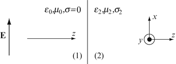
Figure 13.29
-
13.2
Incident and Reflected Waves at a Lossless Dielectric Interface. A plane wave is given as E = E 0e−jβz [V/m] and propagates in free space. The wave hits a dielectric wall (ε = 2ε 0 [F/m]) at normal incidence. With E 0 = 10 V/m, μ 0 = 4π × 10−7 H/m, ε 0 = 8.854 × 10⁻¹² F/m, f = 1 GHz, calculate:
-
(a)
The peak electric field intensity, left of the wall.
-
(b)
The peak magnetic field intensity, left of the wall.
-
(a)
-
13.3
Incident and Reflected Waves at a Lossy Dielectric Interface. The configuration in Figure 13.29 is given. A wave propagates in the direction perpendicular to the interface between free space and a general lossy material (z direction) and has an electric field intensity directed as shown. Calculate the ratio between the maximum and minimum electric field amplitudes in material 1.
-
13.4
Application: Transmission of Power into Solar Cells. Consider the question of generating electricity with silicon solar cells. The relative permittivity of silicon at optical wavelengths is 1.75 m and it may be considered to be lossless. Assume uniform plane waves, perpendicular incidence, and that 25 % of the power entering the cells is converted into electric power. The Sun power density at the location of the cells is 1,400 W/m2.
-
(a)
Calculate the power per unit area of the cell it can generate and its overall efficiency.
-
(b)
Suppose a new type of material is designed which has properties identical to those of silicon except that its permittivity equals that of free space. How much larger is the power that solar cells made of this material can generate and its efficiency?
-
(a)
-
13.5
Power Transmitted into Glass at Normal Incidence. A laser beam is incident on a glass surface from free space. The beam is narrow, 0.1 mm in diameter, with a power density in the beam of 0.1 W/m2. Assume normal incidence on the surface and plane wave behavior. Glass is lossless and has a relative permittivity of 1.8 at the frequency used:
-
(a)
Calculate the amplitude of the incident electric and magnetic field intensities in space and the transmitted electric and magnetic field intensities in the glass.
-
(b)
Calculate the total power transmitted into the glass.
-
(a)
-
13.6
Show that time-averaged power is conserved across an interface between two media for:
-
(a)
Lossless media, perpendicular incidence.
-
(b)
Lossy media, perpendicular incidence.
-
(a)
-
13.7
Application: The Sun at the Beach or: Why Do We Get Sunburns? The Sun impinges on the ground at 1,300 W/m2 (time-averaged power density). If the properties of the skin are known as σ = 0.01 S/m, μ = μ 0 [H/m] and ε = 24ε 0 [F/m], calculate the amount of power dissipated in the skin of a person. Assume the area exposed is 1 m2, the Sun radiates at an average frequency of 5 × 10¹⁴ Hz and is perpendicular to the surface of the skin.
-
13.8
Application: Radiation Exposure. One of the main concerns in exposure to microwave radiation is heating effects in the body. The US radiation safety code specifies that the total amount of radiation should not exceed 10 mW/cm2 of skin for 6 hours. Suppose an average person is exposed to this radiation at a frequency of 10 GHz. The effective area of the skin is 1.5 m2, and the body properties are σ = 0.01 S/m, μ = μ 0 [H/m], and ε = 24ε 0 [F/m], at the given frequency. Calculate the total power absorbed by the body and the total energy absorbed during maximum exposure.

13.1.2 Reflection and Transmission at a Dielectric Conductor Interface: Normal Incidence
-
13.9
Application: Standing Waves and Reflectometry. An antenna generates an electric field intensity in the positive y direction. The amplitude of the generated wave is E 0 = 100 V/m, at a wavelength of 12 m:
-
(a)
Calculate the location of the antenna in relation to a perfectly conducting wall such that a standing wave is generated with three positive maxima in the electric field between the wall and antenna, and the antenna is at the location of the fourth positive peak. Assume propagation in free space.
-
(b)
If propagation occurs in a low-loss medium, ε 1 = 4ε 0 [F/m], μ 1 = μ 0 [H/m], σ 1 = 10−5 S/m, calculate the amplitude of the electric field intensity at the location of the first positive maximum to the right of the antenna.
-
(a)
-
13.10
Reflection of Waves from Conducting Surfaces. A wave propagates in free space and impinges perpendicularly on a perfectly conducting surface. Show that the ratio between the electric field intensity and the magnetic field intensity anywhere to the left of the conducting surface is purely imaginary or that the electric and magnetic field intensities are out of phase. Hint: Use relations ejβz − e−jβz = j2sinβz and ejβz + e−jβz = 2cosβz.
-
13.11
Surface Current Generated by Incident Waves. A wave impinges perpendicularly on a perfectly conducting surface. The amplitude of the incident electric field intensity is 10 V/m and the wave propagates in free space. For orientation purposes, assume the wave propagates in the positive z direction and the electric field intensity is in the negative y direction:
-
(a)
Calculate the surface current density (A/m) produced by the incident field.
-
(b)
Show that the total field in free space is the sum of the incident field and the field produced by the surface current density.
-
(a)
13.1.3 Oblique incidence on a Conducting Interface: Perpendicular Polarization
-
13.12
Interface Conditions at a Conductor Interface. A uniform plane wave impinges on a good conductor at an arbitrary angle. The wave is polarized perpendicular to the plane of incidence.
-
(a)
What are the interface conditions that exist at the interface between the conductor and air?
-
(b)
What happens to the wave inside the conductor (i.e., describe the relations for phase velocity, depth of penetration, intrinsic impedance, and propagation constant)?
-
(a)
-
13.13
Application: Condition of No Reflection—Stealth Principles. A plane wave propagates from the left in free space. It hits a corner of a conducting material and is reflected (Figure 13.30 ). Calculate the angle α for which no power is reflected in the negative z direction. The conductor may be considered to be a perfect conductor. Properties for free space are ε 0 = 8.854 × 10⁻¹² F/m, μ 0 = 4π × 10−7 H/m. You can also assume a unit magnitude for the electric field intensity.
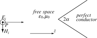
Figure 13.30
-
13.14
Oblique Incidence on a Conducting Surface: Perpendicular Polarization. A perpendicularly polarized plane wave at 100 GHz impinges on a flat metallic reflector at an angle of incidence α. The incident electric field intensity is in the positive x direction, has amplitude 100 V/m, and propagates in free space. Assume the incident magnetic field intensity has components in the positive y and negative z directions and that the interface coincides with the x-y plane. Calculate:
-
(a)
The incident magnetic field intensity.
-
(b)
The reflected electric and magnetic field intensities.
-
(c)
The surface current density as a function of the incidence angle α on the surface of the conductor. Plot its magnitude and show for what values of the incidence angle the current density is maximum and for what values it is minimum.
-
(a)

13.1.4 Oblique Incidence on a Conducting Interface, Parallel Polarization
-
13.15
Oblique Incidence on a Conductor: Parallel Polarization. A uniform plane wave impinges on a good conductor at an arbitrary angle. The wave is polarized parallel to the plane of incidence.
-
(a)
What are the interface conditions that exist at the interface between the conductor and air?
-
(b)
Compare the results obtained here with those in Problem 13.12 .
-
(a)
-
13.16
Oblique Incidence on a Conductor: Parallel Polarization. A parallel polarized plane wave impinges on a flat metallic reflector at an angle of incidence α. The incident magnetic field intensity is in the positive x direction, has amplitude 100 A/m, and propagates in free space at a frequency of 100 GHz. Assume the incident electric field intensity has components in the negative y and positive z directions and the interface is on the x–y plane.
-
(a)
Calculate the incident electric field intensity.
-
(b)
Calculate the reflected electric and reflected magnetic field intensities.
-
(c)
Calculate the surface current density as a function of the incidence angle α on the surface of the conductor. Plot and show for what values of the incidence angle the current density is maximum and for what values it is minimum.
-
(d)
Compare the results obtained here with those in Problem 13.14 .
-
(a)
-
13.17
Show that time-averaged power is conserved across an interface between two media for:
-
(a)
Lossless media, incidence at an angle, perpendicular polarization.
-
(b)
Lossless media, incidence at an angle, parallel polarization.
Hint: Recall that the transmission and reflection coefficients are defined for the tangential components of the electric field intensity.
-
(a)
-
13.18
Standing Waves for Oblique Incidence on a Conductor. A plane wave is polarized parallel to the plane of incidence, its magnetic field intensity is directed in the positive x direction, and it has an amplitude of 15 A/m. Assume the incident electric field intensity has components in the negative y and positive z directions. The phase constant of the wave is 200 rad/m. The wave impinges on a conducting surface on the x–y plane at 30°.
-
(a)
Calculate the standing wave pattern.
-
(b)
Find the location and amplitude of the standing wave peaks.
-
(c)
Calculate the total time-averaged power density in space. Show that real power propagates parallel to the surface.
-
(a)
-
13.19
Propagation of Waves in the Presence of a Conducting Surface. A plane wave is parallel polarized and impinges on the surface of a perfect conductor. For a given amplitude and frequency and assuming the wave propagates in free space before hitting the conductor:
-
(a)
Determine the phase velocity in the direction parallel to the surface of the conductor (in which real power propagates) as a function of the angle of incidence.
-
(b)
What is the phase velocity if the incident wave is parallel to the surface of the conductor?
-
(c)
Compare the results in (a) and (b) with the phase velocity in free space in the absence of the conductor.
-
(a)
-
13.20
Surface Currents Induced by an Obliquely Incident Wave. A plane wave impinges on a perfectly conducting surface at 30° to the normal. The amplitude of the incident electric field intensity is 10 V/m and the wave propagates in free space. Assume the surface is in the x–y plane and calculate:
-
(a)
The surface current density (A/m) produced by the field if the polarization is perpendicular and the incident electric field intensity is in the positive y direction.
-
(b)
The surface current density for parallel polarization if the incident magnetic field intensity is in the positive y direction.
-
(a)
13.1.5 Parallel and Perpendicular Polarization in Dielectrics
-
13.21
Oblique Incidence on a Dielectric: Perpendicular Polarization. A perpendicularly polarized plane wave impinges on a perfect dielectric from free space. The electric field intensity is in the positive x direction, has amplitude E i1, and the incident wave propagates so that it makes an angle θ i to the normal. Assume the magnetic field intensity has components in the positive y and negative z directions and the interface is on the x–y plane. The properties of the dielectric are μ [H/m] and ε [F/m].
-
(a)
Calculate the time-averaged power density in air.
-
(b)
Calculate the time-averaged power density in the dielectric.
-
(c)
What is the most fundamental difference between the two power densities calculated above?
-
(a)
-
13.22
Oblique Incidence on a Dielectric. A uniform plane wave is incident at an angle on an interface between two perfect dielectrics incoming from dielectric (1). The interface coincides with the y–z plane and the dielectrics have properties μ 2 = μ 1 = μ 0 [H/m], ε 2 = 3ε 0 [F/m] and ε 1 = 2ε 0 [F/m]. The scalar components of the incident electric field are E ix = 10 V/m and E iy = 5 V/m:
-
(a)
Find the angle of incidence and the transmission angle.
-
(b)
Identify the polarization of the wave in relation to the given geometry.
-
(c)
Calculate the reflection and transmission coefficients.
-
(d)
From (a) and (c), find the scalar components of the reflected and transmitted waves.
-
(a)
-
13.23
Phase Shift of Transmitted and Reflected Waves. A plane wave at given amplitude and frequency propagates in free space, is polarized perpendicular to the plane of incidence, and impinges on the surface of a high-loss dielectric at an angle θ:
-
(a)
Find the phase shift of the wave at the interface between air and the lossy dielectric; that is, find the phase shift of the transmission coefficient.
-
(b)
Is there also a phase shift in the reflected wave? If so, calculate this phase shift.
-
(a)
-
13.24
Phase Velocity and its Dependence on Incidence Angle. A plane wave is parallel polarized and impinges at 30° to the normal, on the surface of a perfect dielectric with relative permittivity ε r and relative permeability μ r . For a given amplitude and frequency and and assuming the wave propagates in free space before hitting the dielectric:
-
(a)
Determine the phase velocity in the direction parallel to the surface of the dielectric (in which real power propagates) as a function of the angle of incidence.
-
(b)
What is the phase velocity if the incident wave is parallel to the surface of the dielectric?
-
(c)
Compare the results in (a) and (b) with the phase velocity in free space in the absence of the dielectric.
-
(d)
Compare the answers in (a) and (b) with those in (a) and (b) in Problem 13.19 .
-
(a)
-
13.25
Reflection Coefficient and its Dependency on Angle of Incidence. Calculate the reflection coefficient for a planar surface of Teflon versus incidence angle when the electric field intensity remains tangential to the surface and when the electric field intensity has both a normal and a tangential component. Properties of Teflon are ε = 2.1ε 0 [F/m] and μ = μ 0 [H/m]. Plot the reflection coefficients for an incidence angle between zero and π/2.
-
13.26
Parallel and Perpendicular Incidence: Reflection and Transmission Coefficients. After obtaining the general expressions for the reflection and transmission coefficients in Eqs. ( 13.119 ) and ( 13.120 ), find the reflection and transmission coefficients for parallel (θ i =90°) and perpendicular incidences (θ i = 0°) on a perfect dielectric.
-
13.27
Measurement of Thickness of Dielectrics. To measure the thickness of a dielectric material (or if thickness is known its dielectric constant), a collimated wave is sent at an angle θ 1 (Figure 13.31 ). By receiving the reflection from the first surface and from the second surface, the distances d 1 and d 2 can be directly related to the thickness or dielectric constant of the material. Find the relation needed to measure d. Assume parallel polarization, all material properties are known, dielectric and free space are lossless, and the beam is a narrow beam. Given ε 0 [F/m] and μ 0 [H/m] for free space, ε 1 = 4ε 0 [F/m], μ 1 = μ 0 [H/m] for the dielectric, d 1 and d 2 are known, and d 3 = 10 mm.
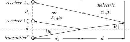
Figure 13.31

13.1.6 Brewster's Angle
-
13.28
Brewster's Angle in Dielectrics. Calculate the Brewster angle for the following dielectric interfaces for a wave propagating from material (2) into material (1):
-
(a)
Distilled water (1) and air (2): ε 1 = 24ε 0 [F/m], ε 2 = ε 0 [F/m], μ 2 = μ 1 = μ 0 [H/m].
-
(b)
Plexiglas (1) and air (2): ε r1 = 4, ε r2 = 1, μ 2 = μ 1 = μ 0 [H/m].
-
(c)
Teflon (1) and air (2): ε r1 = 2.25, ε r2 = 1, μ 2 = μ 1 = μ 0 [H/m].
-
(a)
-
13.29
Calculation of Permittivity from the Brewster Angle. A plane electromagnetic wave is incident on the surface of a dielectric at 62° from air (free space). Calculate the permittivity of the dielectric if at this angle there is no reflection from the surface. Assume parallel polarization of the wave.
13.1.7 Total Reflection
-
13.30
Critical Angles in Dielectrics. What are the critical angles for the following dielectric interfaces? The wave propagates from material (1) into material (2) and all materials have permeability of free space:
-
(a)
Distilled water (1) and air (2): ε 1 = 24ε 0 [F/m], ε 2 = ε 0 [F/m].
-
(b)
Plexiglas (1) and glass (2), ε r1 = 4.0, ε r2 = 1.75.
-
(c)
Teflon (1) and air (2), ε r1 = 2.25, ε r2 = 1.
-
(a)
-
13.31
Application: Use of Critical Angle to Measure Permittivity. A plane electromagnetic wave is incident on the surface of a dielectric at 36° from within the dielectric, at the interface between the dielectric and free space. Calculate the relative permittivity of the dielectric if at this angle there is total reflection from the surface. Assume the dielectric has permeability of free space.
-
13.32
Critical Angle in Dielectric. A plane wave with parallel polarization is incident on the interface between a perfect dielectric and free space, at 28° from within the dielectric. The dielectric has permeability of free space and relative permittivity ε r = 4. Calculate:
-
(a)
The reflection and transmission coefficients at the interface.
-
(b)
The critical angle.
-
(a)
-
13.33
Application: Design of Sheathing for Optical Fibers. An optical fiber is made of glass with a thin plastic coating as shown in Figure 13.32 . Both materials are transparent at the frequencies of interest. Relative permittivity of glass is 2.25 and that of the plastic material may be chosen as (1) 4.0 or (2) 2.0. The optical fiber operates in free space:
-
(a)
Which coating is a better choice and why?
-
(b)
Calculate the critical angle for propagation inside the glass material, based on your answer in (a).
-
(c)
Suppose propagation is also allowed in the coating. What is now the critical angle for propagation?
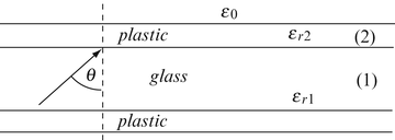
Figure 13.32
-
(a)

13.1.8 Reflection and Transmission for Lossy and Lossless Dielectric Slabs at Normal Incidence
-
13.34
Propagation through lossless slab. A lossless dielectric layer of thickness d [m] and material constants ε 2 [F/m], μ 2 [H/m], and σ 2 = 0 are given. The dielectric is in free space (Figure 13.33 ). Assume a plane wave at frequency f impinges on the dielectric (perpendicular to the surface) from the left. Calculate the total electric field intensity in materials (1), (2), and (3) and the slab reflection and transmission coefficients.
-
13.35
Propagation Through Lossless Dielectric Slab. A dielectric layer of thickness d [m] and material constants ε 2 [F/m], μ 2 [H/m] is given as shown in Figure 13.33 . The dielectric is lossless, in free space. Assume a plane wave impinges on the dielectric (perpendicular to the surface) from the left. Given: μ 2 = μ 0 [H/m], ε 2 = 4ε 0 [F/m], σ 2 = 0, f = 1 GHz, d = 0.01 m.
-
(a)
Calculate the intrinsic impedances in material (1), (2), and(3).
-
(b)
Assuming the incident electric field intensity is known, find expressions for the electric and magnetic field intensities in each material.
-
(c)
Evaluate the electric and magnetic field intensities in material (1) at the interface, in material (3) at the interface, and in material (2) at d/2. Assume the amplitude of the incident electric field intensity is 1 [V/m].
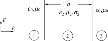
Figure 13.33
-
(a)
-
13.36
Conditions for Transparency of Dielectrics. Given a dielectric slab in free space, with material properties μ = μ 0 [H/m], ε = 4ε 0 [F/m], σ = 0, what must be the thickness of the slab so that there is no reflection from the material at 1 GHz (i.e., the slab reflection coefficient at the surface is zero)? Is this at all possible with the material properties given?
-
13.37
Conditions for Transparency. A perfect dielectric of thickness d [m] is placed in front of a perfect conductor. Write an expression for the thickness of the dielectric for which the slab reflection coefficient is zero. Show that this condition cannot be satisfied for any perfect dieletric.
-
13.38
Application: Design of Radomes. A radome is placed in front of a radar antenna to protect the antenna from the elements. Material properties of the radome are known and the radome is a perfect dielectric. Calculate the minimum thickness of the radome so that the radome is transparent for waves propagating from the antenna and to the antenna. The radome properties are μ = μ 0 [H/m], ε = 4ε 0 [F/m], σ = 0, f = 10 GHz. Use properties of free space for air.
-
13.39
Application: Design of a Dielectric Window. In a microwave oven it is necessary to place a transparent dielectric window made of a quartz sheet between the magnetron (microwave power generator) and the cavity of the oven, so that the magnetron operates under vacuum. If the oven operates at 2.45 GHz, what must be the thickness of the quartz sheet? Use μ = μ 0 [H/m], σ = 0 and ε = 3.8ε 0 [F/m] for quartz and μ 0, ε 0 everywhere else.
-
13.40
Propagation Through a Lossy Dielectric Slab. Solve Problem 13.35 but now the dielectric is a lossy material with conductivity σ 2 = 0.001 S/m.
-
13.41
Propagation Through a Two-Layer Slab. A two-layer dielectric slab in free space is given as shown in Figure 13.34. An incident wave propagates from material (1) and impinges on the first dielectric interface at z = 0. The wave has an electric field intensity of magnitude E 0 = 1 V/m directed in the x direction and is at frequency 150 MHz. Hint: Set up the general equations in each section of space and match the fields at the interfaces. Set up a system of equations based on these relations to solve for the forward and backward components in each section and solve for the numerical values of the fields. Find:
-
(a)
The electric and magnetic field intensities everywhere.
-
(b)
The reflection and transmission coefficient of the composite slab.
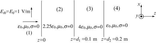
Figure 13.34
-
(a)
-
13.42
Transmission of Power Through an Interface. A plane wave with an electric field intensity equal to E 0 [V/m] propagates from free space into a material with properties ε 1, μ 1, σ 1, and thickness 1 m. The direction of propagation is perpendicular to the surface of the material. Calculate the time-averaged power dissipated in material (1) per unit area of the material. Given: ε 1 = 2ε 0 [F/m], μ 1 = 50μ 0 [H/m], σ 1 = 10 S/m, frequency = 100 MHz, E 0 = 100 V/m.


13.1.9 Reflection and Transmission for a Dielectric Slab Backed by a Perfect Conductor: Normal Incidence
-
13.43
Reflection from a Conductor-Backed Slab. A perfect dielectric of permittivity ε 2 [F/m], permeability μ 2 [H/m], and thickness d [m] is backed by a perfect conductor as shown in Figure 13.35 . A plane wave is incident from the left as shown:
-
(a)
Assuming that the incident wave is known, calculate the reflection coefficient at the interface between free space and dielectric.
-
(b)
Calculate the required thickness d for the reflection to be maximum.
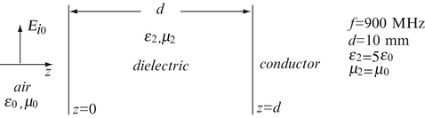
Figure 13.35
-
(a)

Rights and permissions
Copyright information
© 2015 Springer International Publishing Switzerland
About this chapter
Cite this chapter
Ida, N. (2015). Reflection and Transmission of Plane Waves. In: Engineering Electromagnetics. Springer, Cham. https://doi.org/10.1007/978-3-319-07806-9_13
Download citation
DOI: https://doi.org/10.1007/978-3-319-07806-9_13
Publisher Name: Springer, Cham
Print ISBN: 978-3-319-07805-2
Online ISBN: 978-3-319-07806-9
eBook Packages: EngineeringEngineering (R0)