
Abstract
Subsurface drainage systems remove excess groundwater below the ground surface. Perforated plastic drain tubes are placed between 1 and 2 m below the soil surface. The technique was originally called tile drainage because tile cylinders were laid end to end in a trench. Spacing and depth of drain tubes as well as lateral hydraulic conductivity of soil layers determine the rate of water removal from the field. Lateral hydraulic conductivity is generally measured with auger hole tests. Drainage can impact downstream water quality because it changes the timing of water and chemical leaching through the soil. Drainage planning and design require extensive analysis of hydrology, soil structure and texture, soil chemistry, crop rotations, field equipment, topography, waterways, and construction materials. The sizing of drainage pipes is based on the land slope and expected flow rate to pipes. Pipe layout and slope is a function of land slope and discharge location in the field. If the discharge waterway is higher than the drain outlet, then a sump and pump must be installed. Gravel envelopes or fabrics protect drain tubes from sedimentation.
This is a preview of subscription content, log in via an institution.
Buying options
Tax calculation will be finalised at checkout
Purchases are for personal use only
Learn about institutional subscriptionsReferences
ASABE Standards (2015) Design and construction of subsurface drainage systems on agricultural lands in humid areas. ASAE EP260.5. February 2015. American Society of Agricultural and Biological Engineering
Ernst LF (1955) A new formula for the calculation of the permeability factor with the auger hole method. TNO, Groningen
Fogiel A, Belcher H (1991) Research literature review of water table management impacts on water quality. Agricultural Engineering Department, Michigan State University/Land Improvement Contractors of America, East Lansing, p 111
Huffman R, Fangmeier D, Elliott W, Workman S (2013) Soil and water conservation engineering. American Society of Agricultural and Biological Engineering, St. Joseph, Mich
Natural Resources Conservation Service (2001) Part 650 Engineering field handbook chapter 14 water management (Drainage). http://directives.sc.egov.usda.gov/OpenNonWebContent.aspx?content=17551.wba
Natural Resources Conservation Service. Section 16, National engineering handbook. chapter 4. Drainage of agricultural land. http://directives.sc.egov.usda.gov/OpenNonWebContent.aspx?content=18365.wba
USBR (1993) Drainage manual: a water resources technical publication. US Department of the Interior, Bureau of Reclamation. pp 1–59, 147–174. http://www.usbr.gov/pmts/wquality_land/DrainMan.pdf
Author information
Authors and Affiliations
Questions
Questions
-
1.
List the positive and negative environmental aspects of subsurface drainage.
-
2.
What measures are recommended by the NRCS to reduce the impact of drained water from farmland on the environment.
-
3.
List the features that should be noted in a drainage reconnaissance survey.
-
4.
Based on the geometry of Fig. 30.1 and the derivation of Eq. 30.1, are drains designed for the peak flow with the water table directly over the drain after a rainstorm?
-
5.
Derive a drainage coefficient equation for flow with the water table directly over the drain. Compare the ratio of flow rates based on your equation and Eq. 30.4. Discuss why drains are not designed based on the flow rate that takes place when the water table is directly over the drain.
-
6.
Derive Eq. 30.6 from Manning’s equation assuming that the pipe is full and half full and determine whether the equation assumes that the drain is flowing half full of full.
Section
Area A
Wetted perimeter, P
Hydraulic radius R
Top width T
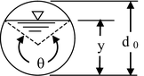
Culvert
\( \frac{1}{8}\left(\theta - \sin \theta \right){d}_0^2 \)
\( \frac{1}{2}\left(\theta \right){d}_0 \)
\( \frac{1}{4}\left(1-\frac{ \sin \theta }{\theta}\right){d}_0 \)
\( \left( \sin \frac{\theta }{2}\right){d}_0 \)
-
7.
A 5 ha area has a drainage coefficient of 19.1 mm/day. The drain slope is 0.3 %. Calculate the required drain size.
-
8.
Calculate the required diameter of a subsurface drain for the following parameters.
Manning’s n
0.017
Drain elevation above impermeable layer
3 m
Drain slope
s = 0.2 m/100 m
Hydraulic conductivity
K = 2 m/day
Drain spacing
L = 60 m
Length of drain pipe
Ld = 500 m
Maximum WT height above drains:
m0 = 2 m − 0.48 m = 1 m
-
9.
Can a geotextile filter be used in a loam soil? What mesh is recommended ?

Rights and permissions
Copyright information
© 2016 Springer International Publishing Switzerland
About this chapter
Cite this chapter
Waller, P., Yitayew, M. (2016). Subsurface Drainage Design and Installation. In: Irrigation and Drainage Engineering. Springer, Cham. https://doi.org/10.1007/978-3-319-05699-9_30
Download citation
DOI: https://doi.org/10.1007/978-3-319-05699-9_30
Publisher Name: Springer, Cham
Print ISBN: 978-3-319-05698-2
Online ISBN: 978-3-319-05699-9
eBook Packages: Earth and Environmental ScienceEarth and Environmental Science (R0)