
Abstract
Waiting for patients and looking for or loosing assets in healthcare costs millions/year and may cause considerable annoyance for caregivers and additional health risks for patients. Localization solutions for healthcare may help to reduce these significantly. This paper provides an overview on localization for Healthcare. It starts with an overview of applicable technologies for both indoor and outdoor localization that may be applied in healthcare logistics solutions. The next section describes various aspects that needs to be considered for an end-to-end localization solution. It is followed by a section on use-cases for healthcare with different operational requirements that may deploy technologies and methods as presented. The final section is on building a use-case concept demonstrator taking into account the technologies and considerations addressed in the previous sections. Security and privacy aspects are also considered to comply with EU healthcare regulations, especially when dealing with personal location data.
You have full access to this open access chapter, Download chapter PDF
1 Terminology and Technology
A state-of-the-art topology of a location awareness solution for healthcare is shown in Fig. 1. It may involve various RF technologies with different characteristics for indoor localization and GPS for outdoor localization of assets and people. These technologies as well as non-RF technologies will be addressed in the following subsections.

Major RF technologies for indoor and outdoor localization in healthcare
1.1 Positioning, Localization, Tracking and Navigation
Before addressing technologies it is important to distinguish some basic terminology as used regarding location awareness in this paper:
Positioning is about determining the absolute or relative position of an asset on a map or a floorplan in a coordinate system. Positioning can be done using 1, 2 or 3 dimensional coordinates or simply by indicating a zone number or area code. The latter is sometimes referred to as 0-dimensional positioning.
For a geographical map a position typically will be expressed in geo-coordinates (latitude, longitude, altitude). For a local map or floorplan coordinates (x,y,z) can be expressed as the distance (x,y) with a certain unity (for example meters or feet) to a reference (corner) position and optionally a floor level number (z).
Localization is about visualizing the physical location of an asset on a map or floorplan to a user.
Tracking is about tracing the positions or locations of an (moving) asset over time.
Navigation is about getting guidance on a map to find the shortest, easiest, or fastest route to a required asset or specified destination.
1.2 RF-Based Indoor Localization Technologies
A typical RF-based Real Time Location System (RTLS) is made up of multiple receivers, often called “beacons” or “anchors” on the ceiling/walls and transmitters, called “tags”, on the assets to be tracked. The tags send signals to the anchors that are connected to a network. The received tag signals are sent to a back-end server that calculates the position of the tags in real-time using proximity (strongest signal), trilateration (estimating distances based on received signal strength) or triangulation (received signal direction based) as shown in Fig. 2. The server can provide the tag position(s) to an application in order to show the location(s) on a dashboard to the user. The tag itself does not know its position.

Trilateration (RSSI based) versus Triangulation (direction based) position estimation
Indoor Navigation Solutions (also sometimes referred to as Indoor Positioning System (IPS)) work in the opposite way. A device (usually a smartphone) will receive signals from “beacons” on the ceiling/walls. The device will then calculate its position and present it to the user for localization or navigation purposes.
Location fingerprinting can be used to identify a position more reliably by matching a received signals profile to predetermined location reference profiles using Machine Learning [1]. Fingerprinting typically requires a time-consuming survey of the RF environment and is prone to errors due to changes of this environment.
Various RF-based wireless technology options are available for a positioning system such as Bluetooth, Wi-Fi, UWB. These are described in more detail below. Various non-RF based methods are described in the section here after.
Different state-of-the art technologies that can be used for indoor localization are described in the following subsections:
1.2.1 Bluetooth
Bluetooth Low Energy (BLE) can be used to do indoor localization using simple BLE beacons as tags and multiple receivers measuring RSSI to estimate the tag position. This provides a basic low cost, low energy solution with a low accuracy. It can be widely used in hospitals by reusing network infrastructure with BLE-enabled Wi-Fi Access Points (AP). If needed the accuracy can be improved using fingerprinting technologies.
Bluetooth 5.1 has RF provisions for Angel of Arrival (AoA) or Angel of Departure (AoD) detection that allows more accurate localization with proper beacon installations. The 5.1 specification adds a Continuous Tone Extension (CTE) to a Bluetooth packet to enable a receiver to calculate the position of its transceiver from the RF signal [2]. BLE tags can be both low-cost and low energy, but a network gateway function is required to make the data available on the internet. Note that Time-of-Flight (ToF) for accurate distance finding between beacons is not in the scope of Bluetooth 5.1, so the distance between beacons should be known in advance or determined less accurate using RSSI. Whether AoA or AoD should be used depends on the use-case:
-
In an AoA direction finding asset tracking system (such as a RTLS) the tag uses a single antenna and conventional Bluetooth LE SoC to send Bluetooth 5.1 packets with CTE. The main computation occurs on the multi-antenna locator side of the system where the signal data gathered by the locator is fed to a location engine that runs the direction-finding algorithms.
-
In an AoD direction finding indoor positioning system (IPS) the fixed beacons use antenna arrays to send Bluetooth 5.1 packets with CTE. The main computation occurs on a mobile device, such as a person’s smartphone (Fig. 3).
Fig. 3 
Bluetooth 5.1 solution for asset tracking based on AoA

1.2.2 Wi-Fi
The big advantage of using Wi-Fi for indoor localization is that the wireless infrastructure is already there in enterprise environments like hospitals and offices. Unfortunately, it is not reliable as it typically depends on trilateration. This also means that the physical AP distribution needs to be considered accordingly. Using signal-strength based location fingerprinting may help to improve the accuracy at the cost of creating (offline) a floorplan based signature list and the risk of mismatches in a changing environment.
As example for a Wi-Fi-based locating solution, the Cisco Connected Mobile Experiences (CMX) [3] Detect and Locate service enables viewing and tracking of APs and clients (including Wi-Fi tags) in an enterprise Wi-Fi deployment (Fig. 4). Typical accuracy is about 10 m.

Screenshot from CMX system showing the location of a Wi-Fi tag (red dot) and nearby APs (blue dots) in a test setup.
The CMX service has recently been integrated into Cisco Spaces that includes additional features for i.a. behavior metrics, location analytics and partner integration. Other Wi-Fi network suppliers (e.g., Aruba, Extreme Networks, Alcatel Lucent) provide similar solutions for device localization.
The Wi-Fi Alliance has recently developed Release 2 of Wi-Fi Location using RTT (Round-Trip-Time) to estimate distance between a device and an AP [4]. It is based on IEEE 802.11az (successor of 802.11mc) and offers the following features:
-
Improved accuracy, about 1 m for enterprise positioning and less than 1 m for proximity detection.
-
Improved operation in Non-Line-of-Sight (NLOS) conditions, by leveraging Wi-Fi 6 Multi-User MIMO technology.
-
MAC/PHY Security, including prevention against eavesdropping and impersonation and protection against false sense of distance.
Reference chipsets are available from Broadcom and NXP. Google provides an API for Android Wi-Fi Location ranging with RTT.
Wi-Fi can also be used to roughly determine the locations of assets outside the hospital using the signals strength of received APs with known locations. The location accuracy depends on the size and actuality of the AP database. Google, Here and others (including open source) maintain such databases and offer APIs to get a geographical location based on a list of detected APs.
1.2.3 UWB
Ultra-Wideband (UWB) also provides a reliable and accurate way of asset tracking using tags attached to or integrated with assets [5], but it requires a dedicated infra-structure for the UWB receivers.
UWB solutions are based on Time of Flight (ToF) method for calculating the distance between two transceivers by multiplying the ToF of the RF signal by the speed of light. The signal pulses used to measure the ToF can be short (typically 2–3 ns) due to the ultra-wide RF bandwidth (>500 MHz). The short UWB pulses prevent interference from reflected signals, resulting in a much higher ranging accuracy than non-wideband solutions.
UWB ranging can be done using either Two-way ranging (TWR) or Time difference of arrival (TDoA) as shown in Fig. 5. The TWR method requires two-way communication between a tag and three or more anchors, avoiding the need for accurate synchronization between the anchors at the cost of a higher energy consumption for the tags. TDoA requires accurate synchronization between the anchors, but the energy consumption for the tags can be lower without the need to receive. Angle of arrival (AoA) detection may optionally be added to the anchors to improve accuracy or to reduce the number of required anchors.

UWB using either TWR or TDoA for distance measuring. TWR requires bidirectional communication between anchors and tags whereas TDoA requires anchor synchronization
For asset tracking BLE and Wi-Fi may be more cost effective, but with respect to either data privacy, communication security, and location accuracy UWB technology may be a better choice. BLE and Wi-Fi tracking accuracy in combination with its wide scale use on modern smartphones is also considered as a privacy concern w.r.t. potential stalking and surveillance. However, UWB based tracking of many assets in a crowded and noisy RF (hospital) environment may significantly degrade its reliability and accuracy due to a lack of LoS [6].
1.3 Non-RF Based Localization Technologies
1.3.1 InfraRed (IR)
Infra-red systems provide a reliable way of asset tracking using tags attached to, or integrated with assets, but they require a dedicated infra-structure for the IR receivers/transmitters (both directions are possible: either tag receives IR signal and transmits to server or the other way round). Unlike RF technologies, IR signals do not pass-through walls and ceilings, which is an advantage for having room level and even bed-level accuracy and certainty. An example of a healthcare IR solution [7] is shown in Fig. 6.

IR tag-based localization solution
The following operational steps are involved in using this solution:
-
IR beacons are installed in all areas where assets need to be tracked. All beacons send out regularly (e.g. every 1.5–3 s) an IR code. Areas can be grouped to define a so-called zone.
-
A communication infrastructure of hubs is set-up which build the communication network for all components of the IR solution. Hubs are the only cabled components of the solution (with Power over Ethernet, PoE).
-
A person or asset is given a battery-powered IR tag.
-
The tag is always active. It scans for IR signals e.g. every 1.5–3 s (configurable).
-
The tag receives an IR zone-id from the beacons and emits a (900 MHz) RF signal with its tag-id and the zone-id to communications hubs.
-
The Communication Hubs send the IR tag-id and IR zone-id to a central server using a LAN.
-
A dashboard program on a computer connected to the server collects and displays the location data.
1.3.2 QR Codes
A very simple way of obtaining one’s location may be by using QR tags with the geolocation or area/zone code, where it is placed, stored on it. By scanning the QR tag with an appropriate application it is clear where the person or asset is [8]. An advantage of such a solution is that it may also work in situations where the network infrastructure is down or not available. A disadvantage is that it typically requires manual actions and scanning is not a low energy operation (Fig. 7).

QR location tag example with geoJSON data
2 Pedestrian Dead Reckoning (PDR)
PDR on a smartphone may be used for tracking or navigation of people in a hospital when starting from a known position. PDR systems typically rely on an accelerometer for measuring displacement, a magnetometer for orientation and a gyroscope for detecting turns (Fig. 8). Its accuracy will be low since an accelerometer (as the name implies) cannot measure speed and step counting is not a reliable method to determine displacement as step sizes are variable. It is also not applicable to assets on wheels tracking as no steps will be detected probably.

Accelerometer based PDR relies on step detection
3 Others
In addition to the location solutions described above it is also possible to determine an asset position without having a tag associated with it. This can be done using cameras or Passive Infrared Sensors (PIR) [9] extended with object or people detection. Many of these solutions rely on an existing infrastructure for surveillance purposes. Extending those with localization features will allow for situational awareness in emergency situations but does not allow individual localization as no UIDs are available. For example, in case of a threat such a system will allow to provide a quick overview of how many people are involved, in which areas they are and in which direction they are moving.
3.1 Outdoor Localization Technologies
3.1.1 GNSS/GPS
Using GNSS (Global Navigation Satellite System) or more specifically GPS (Global Positioning System) is the obvious way for outdoor asset positioning [10]. Accuracy for GPS smartphone is up to about 10 m in the open field, but the accuracy may reduce up to 30 m near buildings, bridges, and trees. The accuracy may be improved using filtering and applying map information. PDR (Pedestrian Dead Reckoning) based on accelerometer and gyroscope sensor data may be used to track slowly moving devices.
Getting an initial position may take a considerable time. Each GPS satellite sends a “legacy” (L1 C/A) navigation frame every 30 s. This message consists of two main components:
-
Ephemeris data: used to calculate the position of each satellite in orbit and valid for 2–4 h.
-
Almanac data: information about the time and status of the entire satellite constellation and it is valid for about 2 weeks.
Only a small portion of the Almanac is included in one GPS frame. It takes 25 frames (12.5 min) to get the full Almanac. The full Almanac (15,000 bits) is needed before a GPS fix can be obtained. The Time To First Fix (TTFF) is a measure of the time required for a GPS receiver to acquire satellite signals and navigation data and calculate its position (called a fix).
During a cold start, that is when a GPS module has been off for a few days and does not have actual data in its memory. The full Almanac is required for processing. If the GPS module has clear line of sight to all satellites, the shortest time for TTFF is 12.5 min.
In a warm start scenario, the GPS module has valid Almanac data, is close to its last position (100 km or so) and knows the time within about 20 s. This approximate information helps the receiver estimate the range to satellites. The TTFF for a warm start can be as short as 30 s (1 frame), but typically it is a couple of minutes.
A receiver that has a current almanac, ephemeris data, time and position can have a hot start. A hot start can take from 0.5 s to 20 s for TTFF. Smartphones use Assisted GPS (A-GPS), this allows them to download the ephemeris and almanac data (size 1 ~ 3 kB) over the cell network which greatly reduces the TTFF (Fig. 9).

Assisted GNSS or GPS improves TTFF in adverse signal conditions
Two new methods have emerged recently to reduce energy consumption: transmission of pseudo-ranges for remote position determination, and snapshot reception [11].
The snapshot method for IoT solutions [28] uses only a very short (≥4 ms) interval of the received GNSS signal that is processed in the cloud (including A-GPS support) to reduce energy consumption at the device side at the cost of a reduced accuracy (Fig. 10). Using a reception front-end with sampling frequency equal to 4 MHz, a 1-bit ADC and a snapshot length of 4 ms, the size of an upload packet would be about (4000 kHz × 4 ms/8 = ) 2 kB . The energy saved from normal GNSS processing (typically requiring 1–30 s of data) on the device will outweigh the energy consumption from uploading the snapshot data.

A snapshot receiver uploads GNSS data to the cloud to obtain position, velocity, and time (PVT)
GNSS position accuracy can be improved by using Differential GPS (DGPS) or Real Time Kinematics (RTK), both using correction (and ephemeris) data from a static local GNSS reference station. The combination of RTK with snapshot methodology is called snapshot RTK (SRTK). For healthcare applications this higher level of accuracy will probably not be needed.
Table 1 shows the major characteristics of each method:
Refinements or combinations of the methods above allow for further optimizations on processing, communication, and accuracy tradeoffs.Footnote 1
3.2 Technology Overview
The table below provides an overview of the indoor positioning methods described above and including GNSS/GPS for outdoor. The tag-based technologies are most suitable for asset tracking, whereas the camera and PIR based solutions are more suitable for situational awareness. Combining technologies may be useful to improve the accuracy or range of the solution.Footnote 2
4 Designing an End-To-End IoT Solution
When designing an end-to-end solution based on localization or logistics tags using the technologies as described in the previous section, various aspects need to be considered. These include commissioning, reliable low power wireless area network (LPWAN) communication and battery lifetime of tags, handling transitions from indoor to outdoor, available APIs for providing location and map visualization services on a user dashboard and application specific security and privacy issues. These are described in the following subsections.
4.1 Commissioning
A localization tag needs to be associated with a unique person’s or device’s identity and be securely connected to an IoT network. The process to do so is referred to as commissioning. To do so each localization tag will have its own unique id (UID) associated with each message, which can also be stored on an NFC tag or shown on a sticker with a QR or bar code. A commissioning device (typically a smartphone) that is already securely connected to the network may perform the following steps:
-
Scan this UID (Fig. 11) and register the IoT device for use by the Application(s).
Fig. 11 
Scanning UID from QR code App
-
Optionally configure the IoT device. For a localization tag this may for example be the reporting period or a geofence area.
-
Provision the device for IoT network access (depending on its connectivity technologies). In case of Wi-Fi the “Easy Connect” technology may be used for onboarding IoT devices.
-
Link the device to a person’s or asset’s identity that has been previously registered into the system. Obtaining the person’s or asset’s identity may be done by an additional UID scan operation or by selection from a UI list.

If needed multiple tags (supporting different technologies or functions) can be associated with one person or device by either commissioning both tags separately as described above or by assigning the same UID (if configurable) to both tags.
4.2 Low Power Wide Area Networks (LPWAN)
Cellular IoT is a mobile network technology that connects IoT devices to the internet using the same cellular network as used by smartphones. It has been optimized for low energy operation with limited data. For healthcare IoT applications requiring operation anytime, anywhere without intermediate devices it will be the preferred LPWAN technology, allowing global operation using Mobile Network Operators (MNO) support. The disadvantage is that a subscription cost will be involved. The table below compares major LPWAN technologies:
One interesting LPWAN feature is that IoT device positioning can be done by the network provider(s) based on trilateration providing an accuracy as listed in the table. Although that may not be accurate enough for many use-cases, it may provide a rough position for any IoT device. For emergency services, a reference criterion may be the FCC’s E911 mandate in the US, which requires location of emergency callers to be provided. In summary the 2020 requirement for 2D accuracy for a given set of measurements for indoor calls is that 70% has an accuracy of <50 m. Cellular solutions should preferably fit these accuracy requirements. The LTE Positioning Protocol (LPP) describes various ways to improve accuracy for cellular technologies [29]. The OTDOA (Observed Time Difference of Arrival) method using a standardized Positioning Reference Signal (PRS) allows for up to 27 m accuracy in rural areas.
4.3 Battery Lifetime
One important aspect to consider is the battery lifetime of tags, especially for the asset tracking use-case. These location tags typically operate on a battery that should last a year or longer to prevent the logistics burden for replacing batteries of hundreds of devices weekly or monthly. For indoor localization tags using IR, BLE or Wi-Fi this is feasible. The technologies are already quite energy efficient and by switching to a low energy mode when a tag is not moving (as detected by an accelerometer) battery lifetimes of over a year are achieved in practice. For BLE tags a battery free solution is even possible as demonstrated by the Wiliot IoT pixels devices that harvests energy from local radio waves.Footnote 3 Within the EU Madras project, a solution is investigated to geolocate assets using UWB technology without a battery, also harvesting energy from surrounding UHF waves.Footnote 4
Cellular technologies as required for outdoor localization (Fig. 12) require much more energy and obtaining a battery lifetime of 1 year or more is quite a challenge. Specifying a specific lifetime is complicated as many variables influence energy consumption (Cell coverage, network load, RF propagation, message size, power saving modes). Using LTE-M and assuming good coverage (CL = 154 dB, a reasonable assumption for outdoor location reporting), a (3Wh) battery lifetime of one year or more is feasible with a report interval of 1 h or more and a message size of 84 bytes [12]. Battery lifetime will scale almost linear with the reporting interval but increasing the message size up to 274 bytes will hardly decrease battery lifetime. Tests done the with MCI Logistics tags (Fig. 18) confirm these observations. Apparently, the LTE-M protocol overhead is the main determining factor here. The size of a geoJSON point type message (with empty properties) is about 120 bytes.

Integrated cellular module with both GNSS and cellular IoT
GPS energy consumption adds up significantly to the cellular device for outdoor localization. Assuming good satellite signal reception the energy needed for an hourly position fix is about 0.75 mWh (Fig. 13, uBlox M8) [13].Footnote 5 Assuming again a 3Wh battery, 1 message/hour and a battery lifetime of 365 days for a cellular device (0.34 mWh), the battery lifetime with GPS will reduce to 3000/(24 × 0.75 + 24 × 0.34) = 115 days. When reasonably assuming an outdoor usage percentage of 50% and an indoor battery lifetime of 1 year the expected battery lifetime will be 3000/(12 × 0.75 + 24 × 0.34) = 175 days. This is well below the 1-year requirement. Further extending battery lifetime is possible by preventing outdoor location updates when the tag is not displaced, using A-GPS or snapshot positioningFootnote 6 to reduce acquisition time(s) significantly, using solar energy and/or increasing the battery capacity. Confirmation of the above assumptions and estimates is needed with a state-of-the-art geolocation tag.

Energy needed for first GPS fix (uBlox M8)
One other aspect to consider w.r.t. battery lifetime is that NB-IoT and LTE-M technologies use a high peak current for transmitting data, which cannot be provided by an almost empty battery. This will reduce the effective battery capacity by 10 ~ 20%.
When using LoRa instead of cellular transmission the required tag energy can be reduced significantly, the SemTech RL1110 geolocation chip uses 81uW or less for GPS localization [14] and LoRa transmission, resulting in a 3Wh battery lifetime of >4 years.Footnote 7 Major disadvantage of using LoRa is the lack of global network provider support. Nevertheless, there is a huge LoRa network available using private LoRa APs operating in internationally reserved Industrial, Scientific, and Medical (ISM) bands.
4.4 Going from Indoor to Outdoor
RTLS solutions for medical device asset tracking are available from various vendors. Most solutions support indoor localization only. Room level accuracy would be preferable in most situations, but the technologies providing this (IR, BLE, UWB, …) typically require a dedicated and thus costly infrastructure. Wi-Fi infrastructure thus would be preferred but does not provide this level of accuracy (yet). A hybrid solution may provide the room level accuracy in specific areas (such as lab spaces) and an acceptable accuracy in public spaces using Wi-Fi. Expanding localization coverage to the hospital campus or beyond with a reasonable accuracy will require GPS (Fig. 14).

Localization of assets from the lab space to the parking lot (for example with a wheelchair) requires multiple technologies
Localization tags should preferably support all required technologies to prevent the logistics burden of commissioning and battery replacement of multiple tags. For the same reason battery lifetime should be 1 year or more. This can be easily achieved for the low energy and short-range technologies; it is more difficult for Wi-Fi and GNSS and cellular will be the real challenges here. To maximize battery lifetime such tags should always use the lowest energy technology and only switch to the next level when that signal is lost. Evaluation tests show that when going from indoor to outdoor in the shade of high buildings (“a hospital”), it takes considerable time to acquire a GPS position for reasons as explained in the previous section. When moving away from the building(s) the GPS location is acquired more easily and accurate.
4.5 APIs for Location Services
Multiple Technologies may be combined to improve accuracy, add features, or reduce energy consumption. For example, a location tag with both BLE and Wi-Fi may support higher accuracy localization in building sections with a BLE 5.1 RTLS system installed, whereas Wi-Fi will be used in the remaining building sections to allow for localization with less accuracy. A location tag with both GPS and Wi-Fi may use Wi-Fi to get a more accurate or quicker location coordinates in the presence of buildings with a known Wi-Fi network Basic Service Set Identifier (BSSID, typically the MAC address of the AP).
There are various API services available that provide geolocation estimates based on cell towers and Wi-Fi Access Points (AP) information as detected by the localizing device. Typical cell towers information that needs to be provided include cell id, mobile country code (mcc), location area code (lac), mobile network code (mnc) and received signal strength (RSSI). This type of information will be available at the receiver’s RF module after connection to a cellular network (Fig. 15). Wi-Fi AP information typically contains the AP’s MAC address (BSSID), RSSI and the Wi-Fi channel number. A Wi-Fi connection is not needed to acquire this information, detection of the Wi-Fi network already provides this information at the device side. A successful API location request will return a JSON response with a geolocation and an associated accuracy (radius) estimate. The geolocation data returned is based on location information from a large database with cell tower locations and locations of APs all over the world, acquired using public smartphone data.

Screenshot from uBlox m-center tool connected to the prototype logistics device (Fig. 18), showing the required network parameters (left) for the location API
For the InSecTT use-case several location APIs have been considered:
-
Google’s geolocation API.Footnote 8 This is the API that is used by most Android smartphones when localization is enabled. It supports both Wi-Fi and cellular, it is well documented and is backed by a large and actual location database. For commercial use, a fee is required of about $5 per 1000 requests.
-
Here Network Positioning API.Footnote 9 This API supports 2G, 3G, 4G, and WLAN measurements data. For cellular it supports neighboring cell measurements to improve position accuracy. Registration is required to get an API access key with options to get started for free or a flexible pay-as-you-grow pricing.
-
RadioCells openbmap API,Footnote 10 shown in Fig. 16. It is compatible to Google API and free to use, but their AP location database is much smaller. Unfortunately, it has recently ceased operation.
Fig. 16 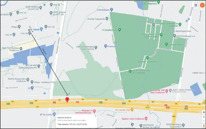
Map showing the cell location as reported by the RadioCells openbmap API with 1000 m accuracy, actual distance to device’s location was <800 m
-
Polte location API.Footnote 11 This location API claims to deliver the best cellular location possible for 4G and 5G Massive IoT devices. Their API comes in two flavors CoreRes and SuperRes. The SuperRes API requires embedded firmware support from a cellular device and provides the highest possible accuracy for cellular localization. Unfortunately, the Polte location API does not support Wi-Fi networks localization and has recently ceased operation.

Evaluation tests show that outside localization based on cellular is up to 100 m accurate, which is not accurate enough for many applications and thus GPS functionality will be required in addition. However, the cell(s) based location (and time) may assist a GPS module to reduce TTFF. Wi-Fi network-based localization on the other side will not be available in many outdoor locations but may help to improve location accuracy in urban areas with many known Wi-Fi networks that may compensate for scattered GPS reception.
4.6 Visualizing on a Map
Visualizing the locations on a dashboard of assets both outdoor and indoor can be done with the Google maps API for Android, iOS or JavaScript (Fig. 17). A disadvantage of this API is that a subscription cost is involved. For the maps SDK this is about $14 for 1000 requests. Indoor floorplans can either be uploaded to Google maps by which they become public or by overlaying them locally. Adding floorplans locally can be done in both bitmap (JPG or PNG) or vector (geoJSON linestring) format. When overlaying bitmap floorplans, the Mercator projection used by Google maps shall be taken into account. The JavaScript version of the API of public maps does not support floor level selection, so local overlays will be needed for buildings with multiple floors.

Screenshot of a web dashboard showing clinical assets locations using the Google maps API with overlays for indoor floorplan
Creating a geoJSON floorplan can be done using geojson.io, a quick, simple tool for creating, viewing, and sharing maps. Floorplans can be drawn manually, but it can also import various file formats (like KML and GPX). Alternatives to Google maps are the HERE Maps API or using the less familiar but free OpenStreetMap (OSM) API.
A dashboard may also need functionality for finding geocoordinates from location names or the other way around. This can be done using a (reverse) geocoding API.
Table 4 shows the major features and costs of the above-mentioned APIs:
4.7 Security and Privacy Aspects
The EU General Data Protection Regulation (GDPR) considers health related data as a special category and provides a definition for health data for data protection purposes [15]. Specific safeguards for personal health data are being addressed by the GDPR. Research and development activities to improve healthcare, such as clinical trials or mobile health need to comply with these data protection safeguards to maintain the trust and confidence of individuals that their data is protected. In the US, the HIPAA Privacy Rule establishes national standards to protect individuals’ medical records and other individually identifiable health information. In general location data is considered as very private sensitive information as demonstrated by the news message below.
40 Attorneys General Announce Historic Google Settlement Over
Location Tracking Practices
November 14, 2022
LANSING – Michigan Attorney General Dana Nessel announced that Michigan, along with 39 other attorneys general, has reached a $391.5 million multistate settlement with Google over its location tracking practices relating to Google Account settings. This is the largest multistate Attorney General privacy settlement in the history of the U.S.
…
Location data is a key part of Google’s digital advertising business. Google uses the personal and behavioral data it collects to build detailed user profiles and target ads on behalf of its advertising customers. Location data is among the most sensitive and valuable personal information Google collects. Even a limited amount of location data can expose a person’s identity and routines and can be used to infer personal details.
5 Healthcare Use-Cases
Within the InSecTT project various use-cases have been considered requiring location awareness for healthcare. These use-cases involve the technologies and end-to-end aspects as described in the previous sections.
5.1 Asset Tracking
This is the simplest application because the tags used for localization of critical equipment themselves are not categorized as clinical devices and hence do not need the associated medical device certifications. Also, there are limited privacy concerns as no personal information is involved. Asset tracking may offer the following advantages [16]:
-
Improved equipment efficiency (typically 30–40% utilization use) by keeping track of equipment use and locations.
-
Improved process workflow as less time will be needed to find nearby equipment. On average nurses take 20 min/shift for finding required equipment.
-
Improved equipment lifetime by automating registration of actual use and keep track of required maintenance.
Localization technologies used for asset tracking can also be used for tracking of patients and personnel, but in that case privacy issues need to be carefully considered. Asset tracking solutions for healthcare are already available from various suppliers, but typically for indoor localization only. Extending these solutions with outdoor localization technologies as described above will allow for a wider scope of applications.
5.2 Mass Casualty Incident (MCI)
In case of mass casualty incidents localization technologies can be used to track locations and triage status of casualties [17]. Traditionally this is done using a paper solution with triage cards attached to casualties and reporting triage status and casualty locations to an incident commander. Properly digitizing the paper solution will provide a better incident overview in chaotic situations and result in better and faster hospital transfers of casualties. Possibly even saving lives (Fig. 18).

Logistics tag for MCI demo in the InSecTT project
5.3 Bed Management
Automated bed management is a specific asset tracking use-case in which not only the location of hospital beds is registered, but also the status of the beds (Unoccupied, occupied, closed, housekeeping, isolated and contaminated according to the FHIR standard, see below). Manually entering and updating this information in the HIS as typically done in most hospitals takes time and leads to inconsistencies between the actual situation and the registered situation [18]. This may be prevented by an IoT solution that updates status and location of beds with a role-based swipe of a badge (Fig. 19).

Workflow for bed management using FHIR defined bed states
5.4 Hospital Wayfinding
Hospitals lose efficiency due to late or missed appointments related to patients arriving late because of traffic delays, parking problems or losing their way around. A navigation (and appointment scheduling) smartphone Application supporting hospital floorplans and indoor localization infrastructure for navigation may prevent these inefficiencies and annoyances [19]. QR codes as described previously may be used for low-cost navigation. Providing patients with a location tag on arrival allows re-use of existing RTLS for navigation purposes.
6 Use-Case Concept Demonstrator
A generic architecture for an IoT logistics solution that supports the use-cases as described above is presented. It has been implemented using cellular localization devices, a geoJSON server with secure authentication, and a dashboard with map visualizations (as shown in Fig. 17). Compatibility with FHIR and location privacy aspects have been considered for the actual implementation.
6.1 Architecture
Figure 20 show a simplified architecture for an autonomous localization solution as used in the InSecTT project for tests and demo. The heart of the system is a secured REST API server with geoJSON data running on the Philips Health Suite Digital Platform (HSDP) using CloudFoundry as a service [20]. Registered location tags can upload their geoJSON data to this server and dashboard client(s) can show the reported locations on a map. This geoServer was developed in JavaScript (ES6) using the node.js framework extended with express for API routing and Postgres SQL database access. A KeyCloak server is used for Identity and Access Management (IAM) providing OAUTH 2.0 authentication and verification. Functional REST API testing was done using POSTMAN. A security assessment of the geoServer was done using the industry standard Common Vulnerability Scoring System (CVSS) [21] to remove all (known) vulnerability risks.

Simplified architecture of an IoT location solution based on the geoJSON standard for data and KeyCloak for OAuth 2.0 authentication
Dashboards for the asset tracking (Fig. 17) and the MCI use-cases were build using HTML/CSS and JavaScript (ES6) to access the geoJSON and Google maps server APIs.
An Arduino SARA-R4 board (Fig. 21) has been used for prototyping and testing the GPS and cellular functionality for outdoor localization. For this purpose, the cellular Sodaq R4X libraryFootnote 12 has been updated to support HTTPS (port 443). Due to firmware (header size) limitations OAUTH 2.0 authentication could not be implemented, so basic authentication is (temporarily) used on the device side. At this point it should also be noted that mutual authentication (using client token generation and TLS server certificate validation) can be a considerable burden for constrained IoT devices, demanding for secure but more lightweight alternatives [22]. For constrained IoT devices TLS overhead may be reduced using session resumption using a client id or a ticket [30, 31]. TLS 1.3 [32] defines a new mechanism 0-RTT (zero round-trip time) that can be considered to reduce TLS overhead,Footnote 13 but its value to IoT devices is not yet clear.

Sodaq Small Form Factor (SFF) board as used for prototyping. The SARA-R4 module supports cellular IoT and a GNSS module (EVA-8 M) can be added. Software can be uploaded via the USB connector and runs on a 32-Bit ARM Cortex M0 + processor. A Tricolor LED is used for showing triage or asset status
With a new generation of GPS/cellular localization devices currently entering the market, the IoT device choice is reconsidered, taking into account the requirements and concerns that have been identified from our prototype testing.
6.2 GeoJSON Server
GeoJSON is an open standard JSON format designed for representing simple geographical features, along with optional properties [23]. Features include points, line strings, polygons, and collections of these types. Thus, it can be easily used for any location tag reporting its geolocation as a point feature (Fig. 22).

Screenshot of a Postman client sending a geoJSON point with various properties (including a timestamp) and a unique id to the geoJSON backend server using a REST API
6.3 Client Authentication
For security and privacy reasons two-way authentication is required for a location solution in healthcare [24]. When using a HTTPS REST API, the positioning device should support TLS with server certificate validation. Due to IoT device constraints Device to Cloud (D2C) authentication may be done using tokens of sufficient length (≥128 bits) and a limited lifetime. Token generation and transmission requires additional energy on the device, so selecting the token length and its validity period will be a trade-off between battery lifetime and security.
6.4 FHIR Compatibility
FHIR (Fast Health Interoperability Resources)Footnote 14 is an international standard for Healthcare Interoperability. FHIR solutions are built from a set of modular components called “Resources” in JSON or XML format. These resources can be combined in hospital systems to manage both clinical and administrative problems. The standard is widely used in mobile applications, cloud communications, EHR-based data sharing, and server communications across the healthcare industry. FHIR server implementations are available from major providers such as Google and Microsoft. Apple is using the (SMART on) FHIR standard to enable their users to download health records and share them with participating organizations. An example of FHIR resources involved in bed status reporting is shown in Fig. 23. The FHIR location resource supports both geographic and address locations, so conversion from geoJSON to a FHIR location (and v.v.) can easily be done.

FHIR resources and references involved in bed status reporting
6.5 Location and Privacy
Although localization solutions do not address privacy directly, location information of persons surely is personal and therefore needs to be handled very carefully and cannot be used without permission except in emergency situations. Geographical masking health data may be used to protect the confidentiality of location records while still allowing for geographically based analyses [25]. For these reasons the geoJSON server only stores the most recent reported location and supports an offset operation on geo-coordinates.
6.6 Additional Features
In this section several features are described that may be considered to support or extend specific healthcare use-cases.
6.6.1 Geofencing
Geofencing can be used to generate an alarm on the dashboard and/or the device if an asset is moving inside or outside a specific area or building. Boundaries could optionally be set at the dashboard side and uploaded to the server possibly using the geoJSON polygon feature type.
6.6.2 Sensors
Additional sensors could be added to a tag as needed. For example, a temperature or humidity sensor that can be used to check the environment for the device associated with the tag. A specific healthcare example could be monitoring a medicine box for transporting medication or tissue from a patient to a lab or v.v.
6.6.3 Analytics
Data gathered from a location tag can be used for statistical analysis on location, transport, usage. Additional sensors or integrated tags and integration with existing FHIR services may help to properly register device specific features, for example bed occupancy.
7 Conclusions/Next Steps
In this paper an overview of most widely used localization methods was presented and how these can be applied to healthcare logistics use-cases using an IoT architecture with standardized data formats like geoJSON and FHIR with a secure REST API.
Visualizing the locations of assets or people both outdoor and indoor can be done with the Google maps API for Android, iOS, or JavaScript. A disadvantage of this APIs is that a variable subscription cost is involved. Indoor floorplans can either be uploaded to Google maps by which they become public or by overlaying them locally. When using the JavaScript version of the API floor level, selection of public maps is not possible, so using local overlays will still be needed. An alternative to Google maps is using the lower cost Here API or the less familiar but free OpenStreetMap API. A floorplan only mode (without overlay) may be included to avoid API subscription cost at all for indoor visualization.
For an RTLS solution supporting outdoor localization of assets it can be concluded from analysis and tests done that battery lifetime strongly limits the period for GNSS position reporting using cellular IoT (LTE-M). This allows for outdoor localization but prevents real-time tracking of assets for a longer period. Also, it was observed that outdoor GNSS acquisition might be difficult in the shade of large buildings (as hospitals) when moving the asset from inside to outside even when using A-GNSS. New generations of GNSS receivers designed for IoT using snapshot technology may improve significantly on tag battery lifetime allowing 1 year or more of operation. When using LoRa such a long battery lifetime will be easier to achieve, but LoRa does not support global business operation.
Multimodal solutions including UWB/BLE/IR, Wi-Fi and GNSS are required to provide an overall cost-effective solution for asset tracking both indoor and outdoor on a healthcare campus.
These findings may help in a next step for setting up a larger scale trial for asset localization with outdoor GNSS tags that fit the established functional requirements. Such a trial may provide further insights into operational requirements and fulfilment of the quadruple aim of creating better health outcomes at lower cost, while improving patient and staff experience.Footnote 15 A business plan is also needed to provide a.o. business requirements, a product or service roadmap, how to handle (cellular, A-GNSS and maps API) subscription costs and a budget for market introduction [26, 27].
Notes
- 1.
Rough estimates based on a battery capacity of about 3000 mWh, a message payload of 25 bytes, sending 1 message/hour and a 5uA sleep current.
- 2.
Assuming roughly 1 k devices, 12 location messages/day, www.emnify.com.
- 3.
- 4.
- 5.
Assuming a TTFF of 30 s and considering that the ephemerides data is only valid for a few hours, see UBLOX Hot Fix Times (u-blox.com).
- 6.
Extend Battery Life with an Ultra-Low Power GPS Solution | Bench(mouser.com).
- 7.
LR1110 chip: one solution for LoRa and GNSS tracking—IoT Blog (irnas.eu).
- 8.
- 9.
- 10.
- 11.
- 12.
- 13.
- 14.
- 15.
Abbreviations
- AoA:
-
Angel of Arrival
- AoD:
-
Angel of Departure
- AP:
-
Access Point
- API:
-
Application Programming Interface
- BLE:
-
Bluetooth Low Energy
- BSSID:
-
Basic Service Set Identifier
- CVSS:
-
Common Vulnerability Scoring System
- CNN:
-
Convolutional Neural Network
- CMX:
-
Connected Mobile Experiences
- CTE:
-
Continuous Tone Extension
- D2C:
-
Device to Cloud
- FHIR:
-
Fast Healthcare Interoperability Resources
- GDPR:
-
General Data Protection Regulation
- GNSS:
-
Global Navigation Satellite System
- GPS:
-
Global Positioning System
- GPX:
-
GPS Exchange Format
- HIPAA:
-
Health Insurance Portability and Accountability Act
- IAM:
-
Identity and Access Management
- IoT:
-
Internet of Things
- IPS:
-
Indoor Positioning System
- ISM:
-
Industrial, Scientific, and Medical
- JSON:
-
JavaScript Object Notation
- LAN:
-
Local Area Network
- LoS:
-
Line of Sight
- LTE:
-
Long Term Evolution
- LPWAN:
-
Low Power Wide Area Network
- MCI:
-
Mass Casualty Incident
- ML:
-
Machine Learning
- MNO:
-
Mobile Network Operator
- IR:
-
Infra-Red
- LOCI:
-
Localization Infrared
- NFC:
-
Near Filed Communication
- OSM:
-
Open Street Map
- QR:
-
Quick Response (code)
- PoE:
-
Power over Internet
- PDR:
-
Pedestrian Dead Reckoning
- RF:
-
Radio Frequency
- RFC:
-
Request For Comment
- RSSI:
-
Received Signal Strength Information
- RTK:
-
Real Time Kinematics
- RTLS:
-
Real Time Location System
- RTT:
-
Round Trip Time
- TLS:
-
Transport Layer Security
- ToF:
-
Time of Flight
- TTFF:
-
Time To First Fix
- TWR:
-
Two Way Ranging
- UWB:
-
Ultra-Wide Band
- WFA:
-
Wi-Fi Alliance
- XML:
-
Extensible Markup Language
References
Completely automated CNN architecture design based on VGG blocks for fingerprinting localisation. In: International Conference on Indoor Positioning and Indoor Navigation (IPIN), Shreya Sinha and Duc V. Le (2021)
“Bluetooth Direction Finding—A Technical Overview”, Martin Woolley, Bluetooth SIG (2021)
White Paper “CMX Analytics”, Cisco/Meraki (2014)
“Wi-Fi CERTIFIED Location”, Wi-Fi Alliance (2022)
Ultra-Wideband (UWB) for the IoT—a fine ranging revolution? Andrew Zignani and Stephanie Tomsett, NXP and ABI research (2021)
Mohammadmoradi, H. et al.: UWB physical layer adaptation for best ranging performance within application constraints. In: Conference Paper (2018)
Sharif-Vakili et al.: A comparison of commercial and custom-made electronic tracking systems to measure patient flow through an ambulatory clinic. Int. J. Health Geogr. (2015)
Indoor navigation with a smartphone, Drago Torkar, Jožef Stefan Institute, Slovenia (2023)
Narayana, S. et al.: LOCI: privacy-aware, device-free, low-power localization of multiple persons using IR sensors. In: ACM/IEEE International Conference on Information Processing in Sensor Networks (IPSN) (2020)
GPS compendium “Essentials of Satellite Navigation”, uBlox (2007)
Whitepaper “Power-efficient positioning for the Internet of Things”, European GNSS Agency (2020)
Power Consumption Analysis of NB-IoT and eMTC in Challenging Smart City Environments, Pascal Jorke, Robert Falkenberg and Christian Wietfeld, Communication Networks Institute, TU Dortmund University, Germany, IEEE Global Communications Conference Workshops (2018)
Whitepaper “Low-power GNSS for tracking applications”, Bernd Heidtman, uBlox (2021)
LR1110 Application Note: LoRa Edge™ Advance Scan Location Performance Overview, Semtech (2022)
Regulation (EU) 2016/679 of the European parliament and of the Council of 27 April 2016 on the protection of natural persons with regard to the processing of personal data and on the free movement of such data, and repealing Directive 95/46/EC (General Data Protection Regulation)
“Top 6 Applications of Healthcare Asset Tracking - Asset Utilization Drives Operational Efficiency”, Whitepaper Airista (2021)
Chang, C.H.: Smart MCI tracking and tracing system based on colored active RFID triage tags. Int. J. Eng. Bus. Manag. (2011)
Bed Management Optimization, Dr Ramachandran Balaji, Mark Brownlee, Infosys (2018)
“Wayfinding Tailored to the Patient Experience”, Datasheet Everbridge (2022)
Brochure “Philips HealthSuite digital platform”, Philips (2020)
User Guide “Common Vulnerability Scoring System version 3.1”, first.org (2019)
“Addressing coverage concerns for Direct-to-Cloud wearables”, Ewout Brandsma, Paul Gruijters, Henk Huijgen and Jesus Gonzalez Tejeria, IEEE (2022)
The GeoJSON Format, Internet Engineering Task Force, RFC-7946 (2016)
“The State of Healthcare IoT Device Security”, A Cynerio Research Report (2022)
Armstrong, M.P., Rushton, G., Zimmerman, D.L.: “Geographically masking health data to preserve confidentiality”, Statistics in Medicine (1999)
Whitepaper PerformanceFlow Solution, “How to innovate mobile asset management in hospitals by providing actionable IoT insights based on real-time location data”, Philips (2021)
Top 6 Applications of HealthCare Asset Tracking – Asset Utilization Drives Operational Efficiency (2021)
Shafran, S.V., Gizatulova, E.A., Kudryavtsev, I.A.: “Snapshot technology in GNSS receivers”. In: 2018 25th Saint Petersburg International Conference on Integrated Navigation Systems (ICINS), St. Petersburg, Russia (2018)
Mahyuddin, M.F.M., Isa, A.A.M., Zin, M.S.I.M., Afifah Maheran A.H., Manap, Z., Ismail, M.K.: “Overview of positioning techniques for LTE technology”. J. Telecomm. Electron. Comput. Eng. (JTEC) 9 (2–13) (2017)
“Transport Layer Security (TLS) Session Resumption without Server-Side State”, RFC 5077 (2008)
“The Transport Layer Security (TLS) Protocol Version 1.2”, RFC 5246 (2008)
“The Transport Layer Security (TLS) Protocol Version 1.3”, RFC 8446 (2018)
Author information
Authors and Affiliations
Corresponding author
Editor information
Editors and Affiliations
Rights and permissions
Open Access This chapter is licensed under the terms of the Creative Commons Attribution 4.0 International License (http://creativecommons.org/licenses/by/4.0/), which permits use, sharing, adaptation, distribution and reproduction in any medium or format, as long as you give appropriate credit to the original author(s) and the source, provide a link to the Creative Commons license and indicate if changes were made.
The images or other third party material in this chapter are included in the chapter's Creative Commons license, unless indicated otherwise in a credit line to the material. If material is not included in the chapter's Creative Commons license and your intended use is not permitted by statutory regulation or exceeds the permitted use, you will need to obtain permission directly from the copyright holder.
Copyright information
© 2024 The Author(s)
About this chapter

Cite this chapter
van de Laar, F., Klabunde, K. (2024). Location Awareness in HealthCare. In: Karner, M., Peltola, J., Jerne, M., Kulas, L., Priller, P. (eds) Intelligent Secure Trustable Things. Studies in Computational Intelligence, vol 1147. Springer, Cham. https://doi.org/10.1007/978-3-031-54049-3_15
Download citation
DOI: https://doi.org/10.1007/978-3-031-54049-3_15
Published:
Publisher Name: Springer, Cham
Print ISBN: 978-3-031-54048-6
Online ISBN: 978-3-031-54049-3
eBook Packages: Intelligent Technologies and RoboticsIntelligent Technologies and Robotics (R0)