
Abstract
This chapter introduces electromagnetic compatibility (EMC), its most essential terms and definitions, and why it is wise to consider EMC early during product development.
I have not failed. I’ve just found 10’000 ways that won’t work.
—Thomas A. Edison
You have full access to this open access chapter, Download chapter PDF
Keywords
- Electromagnetic compatibility (EMC)
- Electromagnetic interference (EMI)
- Radiated emission
- Conducted emission
- Radiated immunity
- Conducted immunity
- Radiated susceptibility
- Conducted susceptibility
- EMC standards
- Design for EMC
- Life cycle cost
- Iterative testing
- Product development
- Product design
- Electrical engineering
- Electrical design
- Development process
1.1 What Is EMC?
Electromagnetic compatibility (EMC) is an established discipline within the field of electrical and electronics engineering. EMC is the ability of equipment or a system to function satisfactorily in its electromagnetic environment without introducing intolerable electromagnetic disturbances to anything in that environment [1]. In other words, each device must have a certain immunity against electromagnetic disturbances, and on the other hand, each device must keep its own electromagnetic emissions low enough to not disturb other devices in its environment (Fig. 1.1).

How an EMC design engineer sees a product
1.2 EMC vs. EMI
EMI stands for electromagnetic interference and is often mixed up with EMC. EMI means that one electronic device A is causing disturbance to another electronic device B, which is in the surrounding of device A.
What is the difference between EMC and EMI? Now, an EMC-compliant product has to be tested on EMI during its development. For an EMC-compliant product, EMI should not happen anymore. This is because EMC-compliant products proved their electromagnetic immunity to be high enough and their electromagnetic emission to be low enough to work seamlessly in its predefined environment.
1.3 Why Is EMC Important?
EMC-compliant products reduce the risk of undesired interference and disturbances. However, why is that so important? EMC is important because interference and disturbances of electrical equipment can seriously harm people, infrastructure, and the environment. For example, in 1992, a woman died because the heart machine of the ambulance shut down every time the technicians turned on their radio transmitter to ask for advice [12]. Another example is the explosion of the Texaco refinery in Milford Haven UK, on the 24th of July 1994, which was caused by an electrical storm giving rise to power surges which tripped out a number of pump motors while leaving others running. The explosion led to 26 people being sustainably injured and damage of £48 million [12]. These are just two of numerous examples and show us that taking care of EMC-compliant design is not just a necessity for selling products; it means a safer world with reliable products and satisfied customers.
1.4 EMC Terms and Definitions
The discipline of EMC can primarily be divided into the subjects of emission and immunity (or susceptibility ). Figure 1.2 shows the most important terms and definitions in EMC. Other EMC abbreviations and acronyms can be found in chapter “Acronyms” in the front matter of this book on page xxiii.

EMC terms and definitions
1.4.1 Emission
It is distinguished between conducted emissions (CE) and radiated emissions (RE).
-
Conducted emissions. Conducted emissions are measured at cables that are connected to the equipment under test (EUT). For commercial and industrial electrical/electronic equipment, it is distinguished between different emission aspects:
-
RF conducted emissions. Goal: prevent connected cables from radiating and avoid the interference of connected equipment. The frequency range of the RF emission measurements for commercial and industrial products goes from 150 kHz to 30 MHz (CISPR 32 [2], FCC 47 CFR Part 15 [3]). However, the frequency range depends on the industry and may be as wide as from 30 Hz to 40 GHz for defense and military products (MIL-STD-461G [13]).
-
Harmonics. Goal: limitation of harmonic currents injected into the public mains supply system. The mains supply input current of many devices and machines is often not a harmonic sine wave.
-
Flicker. Goal: limitation of voltage changes, voltage fluctuations, and flicker in public low-voltage supply systems. Flicker is the impression of unsteadiness of visual sensation induced by a light stimulus whose luminance or spectral distribution fluctuates with time [1].
-
-
RF radiated emissions. Goal: prevent disturbance of nearby electrical and electromechanical equipment. Radiated emissions are measured in an anechoic or semi-anechoic chamber or at an open area test site (OATS). For commercial and industrial products, the frequency range of radiated emission measurements goes from 30 MHz to 6 GHz (CISPR 32 [2]) or 30 MHz up to 40 GHz (FCC 47 CFR Part 15 [3]). However, the frequency range depends on the industry and may be as wide as from 10 kHz to 40 GHz for defense and military products (MIL-STD-461G [13]).
1.4.2 Immunity
It is distinguished between conducted immunity/susceptibility (CI, CS), radiated immunity/susceptibility (RI, RS), and immunity against phenomena like electrostatic discharge (ESD) or electromagnetic pulses (EMP).
-
Conducted immunity. Conducted immunity tests are performed at cables that are connected to the EUT. For commercial and industrial electrical/electronic equipment, it is distinguished between different immunity aspects:
-
RF conducted immunity. Goal: functional immunity to conducted disturbances induced by RF fields. The frequency range of the conducted RF immunity tests for commercial and industrial products goes from 150 kHz to 80 MHz (IEC 61000-4-6 [9]).
-
EFT. Goal: functional immunity to repetitive electrical fast transients (EFT, bursts), such as those originating from switching transients (interruption of inductive loads, relay contact bounce, etc.). Test voltages vary from 0.5 kV to 4 kV (IEC 61000-4-4 [8]).
-
Surge. Goal: functional immunity to unidirectional surges caused by overvoltages from switching and lightning transients. Test voltages vary from 0.5 kV to 4 kV (IEC 61000-4-5 [11]).
-
Dips. Goal: functional immunity to voltage dips, short interruptions, and voltage variations at the power supply ports.
-
-
Radiated RF field immunity. Goal: functional immunity to radiated radio-frequency electromagnetic radiation in the far-field (80 MHz to 6 GHz: IEC 61000-4-3 [6]) or in the near-field (26 MHz to 6 GHz: IEC 61000-4-39 [7]).
-
Radiated magnetic field immunity. Goal: functional immunity to magnetic disturbances at mains power frequencies 50 Hz and 60 Hz (IEC 61000-4-8 [10]) or at wireless charging/inductive power transfer frequencies 9 kHz and 26 MHz (IEC 61000-4-39 [7]).
-
ESD. Goal: immunity to static electricity discharges, from operators directly and from personnel to adjacent objects. Test voltages vary from 1 kV to 15 kV (IEC 61000-4-2 [5]).
-
EMP. Goal: protection against electromagnetic pulses (EMP). An EMP is an instantaneous, intense energy field, which can be caused by a nuclear explosion or other pulse-generating devices. If this explosion happens at a high altitude, it is called a HEMP. EMPs are a topic for defense and military applications and not for commercial and industrial products.
1.5 Design for EMC
Design for EMC means considering EMC early during product development, not just at the end of the project. If you test your product for EMC just shortly before the product is to be launched, project delays and budget overruns result. Figure 1.3 shows that the later a defect in the product life cycle is fixed, the more expensive it is. Here are some essential points regarding EMC and product development:
-
EMC concept. You need to define an EMC concept at the very beginning of the development project (before the first hardware is designed). This EMC concept should especially define the following points:
-
Grounding. Define a grounding concept for the product (system grounding), the subsystems of the product (intrasystem grounding), and PCBAs (board-level grounding).
Fig. 1.3 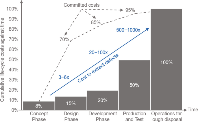
Life cycle costs [4] and the costs of fixing defects at different life cycle stages
-
Shielding. Define if and how to shield sensitive circuits and cables (intrasystem and external cables). Define the bonding of the shields.
-
Filtering. Define if and how cables and wires (intrasystem and external cables) have to be filtered. Especially consider ESD, EFT, and surge for cables that leave your product. RF-filtering should be considered for every cable.
-
-
Iterative testing. It is recommended to test the EMC performance (emission, immunity) at different product development iterations. There are typically four iterations in hardware development projects: breadboard, prototype, pilot, and series. It is good practice to do pre-compliance testing (testing in-house or at a not fully accredited compliance lab) at the prototype stage and fully compliant EMC testing at the later project stages (pilot, series). Pre-compliance EMC testing is an excellent choice to save time and money. Another advantage of in-house EMC testing is the constant improvement of the EMC knowledge of the development team.

1.6 Summary
-
EMC. EMC is the ability of equipment or a system to function satisfactorily in its electromagnetic environment without introducing intolerable electromagnetic disturbances to anything in that environment.
-
EMC tests. EMC tests can be divided into two categories: emission tests and immunity tests.
-
Coupling paths. EMI occurs via conduction (connected cables), via radiation (directly from and to a product), or a combination of both.
-
Design for EMC. Considering EMC design in the early product development stages helps to prevent budget overrun and product launch delays.
References
International Electrotechnical Commission (IEC). Electropedia: The World’s Online Electrotechnical Vocabulary. Feb. 5, 2021. URL: http://www.electropedia.org.
CISPR 32 Electromagnetic compatibility of multimedia equipment – Emission requirements. International Electrotechnical Commission (IEC). 2015.
Code of Federal Regulations - Title 47 - Chapter I - Subchapter A - Part 15 (FCC 47 CFR Part 15). Federal Communication Commission (FCC, USA). 2021.
Commited life cycle costs against time. Fort Belvoir, VA. Defense Acquisition University (DAU). 1993.
Electromagnetic compatibility (EMC) - Part 4–2: Testing and measurement techniques - Electrostatic discharge immunity test. International Electrotechnical Commission (IEC). 2008.
Electromagnetic compatibility (EMC) - Part 4–3 : Testing and measurement techniques - Radiated, radio-frequency, electromagnetic field immunity test. International Electrotechnical Commission (IEC). 2020.
Electromagnetic compatibility (EMC) - Part 4–39: Testing and measurement techniques - Radiated fields in close proximity - Immunity test. International Electrotechnical Commission (IEC). 2017.
Electromagnetic compatibility (EMC) - Part 4–4: Testing and measurement techniques - Electrical fast transient/burst immunity test. International Electrotechnical Commission (IEC). 2012.
Electromagnetic compatibility (EMC) - Part 4–6: Testing and measurement techniques - Immunity to conducted disturbances, induced by radio-frequency fields. International Electrotechnical Commission (IEC). 2013.
Electromagnetic compatibility (EMC) - Part 4–8: Testing and measurement techniques - Power frequency magnetic field immunity test. International Electrotechnical Commission (IEC). 2009.
Electromagnetic compatibility (EMC) – Part 4–5: Testing and measurement techniques – Surge immunity test. International Electrotechnical Commission (IEC). 2014.
Cherry Clough Consultants Ltd. EMI Stories - A collection of 890 real-life short stories about the dangers of electromagnetic interference (EMI). Dec. 8, 2021. URL: https://www.emcstandards.co.uk/emi-stories.
MIL-STD-461G - Requirements for the control of electromagnetic interference charactersitics of subsystems and equipment. Department of Defense (DoD, USA). 2015.
Author information
Authors and Affiliations
Rights and permissions
Open Access This chapter is licensed under the terms of the Creative Commons Attribution 4.0 International License (http://creativecommons.org/licenses/by/4.0/), which permits use, sharing, adaptation, distribution and reproduction in any medium or format, as long as you give appropriate credit to the original author(s) and the source, provide a link to the Creative Commons license and indicate if changes were made.
The images or other third party material in this chapter are included in the chapter's Creative Commons license, unless indicated otherwise in a credit line to the material. If material is not included in the chapter's Creative Commons license and your intended use is not permitted by statutory regulation or exceeds the permitted use, you will need to obtain permission directly from the copyright holder.
Copyright information
© 2023 The Author(s)
About this chapter

Cite this chapter
Keller, R.B. (2023). Introduction. In: Design for Electromagnetic Compatibility--In a Nutshell. Springer, Cham. https://doi.org/10.1007/978-3-031-14186-7_1
Download citation
DOI: https://doi.org/10.1007/978-3-031-14186-7_1
Published:
Publisher Name: Springer, Cham
Print ISBN: 978-3-031-14185-0
Online ISBN: 978-3-031-14186-7
eBook Packages: EngineeringEngineering (R0)