
Abstract
This chapter will describe the activity of Fenix project that consisted in developing the hardware, infrastructure and processes to make possible the re-use of the recycled metals through an Additive Manufacturing (AM) method called Direct Ink Writing (DIW). It will first explain what is DIW and why it is an interesting way to give added value to recycled materials specially metals. It will then focus on the working principles and the parts of a DIW machine and end with a conclusion of the adequacy of this technology to new circular business models for the recycling of Waste of Electric and Electronic Equipment (WEEE).
You have full access to this open access chapter, Download chapter PDF
Keywords
6.1 Direct Ink Writing
6.1.1 DIW Technology Introduction
In a nutshell, DIW also called robocasting consists in depositing a pseudo-plastic ink composed of a solid load of particles and a binder. This paste, contained in a syringe, is deposited using a XYZ positioning system and this “green” part is then sintered in a hoven. During this process the binder is burned, and the solid particles sold together forming a solid metallic part. The solid load can be composed of metallic particles of every element and alloys, it can also be made of ceramics, glasses and last but not least biomaterials, loaded or not with living cells for tissue engineering. This section will start treating the material itself to be printed and then make a quick introduction about the design of DIW fabricated parts (Fig. 6.1).

DIW process
6.1.2 Ink Process Generation for DIW Technology
In Chap. 5 “A mobile pilot plant for the recovery of precious and critical raw materials” UNIVAQ described how the different chemical elements of the WEEEs are obtained through a hydrometallurgical process.
The powder obtained in the hydrometallurgical plant is analyzed to get information on their actual composition via EDX technique. Pre-processing steps can be put in place if the powder result to be too much oxidized (i.e. thermal treatment in Ar/H2 atmosphere) or if the powder morphology is not suitable for the high energy ball milling step (i.e. mild powder grinding via tumbling mills).
The recycled powder is then processed with fresh raw element powders, (i.e. Fe, Ni, P) to produce an alloy suitable for sintering processes. The ratio between new and recycled materials is adjusted batch by batch according to the composition of the recycled powder. In the high energy ball milling step process, the different powders are alloyed at solid state and room temperature conditions. Once the alloyed powder is obtained it is post-processed to optimize morphology and particle size distribution.
A tumbling mill is used to increase the fraction of particles in the usable size range (i.e. particles smaller than 60 µm) and sieves are used to tailor the size distribution (i.e. bimodal or monomodal). Laser diffraction analysis assesses the final size distribution of the batch of powder that is then used to compound a feedstock for robocasting.
Once the metal powder alloy has been successfully obtained and manufactured, the next step is to formulate the appropriate composition. The formulation has been done to develop a material ink to be printed through Direct Ink Writing (DIW) process.
This process consists in the generation of an ink which its characteristics must present a pseudoplastic behavior to be printable by DIW. It is usually recommended to have a solid load by 35–60% to obtain a functional final part. During Fenix project, the development will be focused on increasing the solid load fraction in order to increase part density.
In the Fenix project 8 different powders have been tested, two commercial copper-based powder and six different Fe-based powders have been developed (monomodal and bimodal) (Fig. 6.2).

Powders used during the project
8 different types of inks are obtained from mixing theses powder with a binder formed of pluronic acid and a dispersing agent, with a Powder/Binder ratio of 45% in volume (82% in weight for the FNX31 powder). The following scheme presents the process of the material generation (Fig. 6.3).

Scheme of the process material generation
The procedure to make the ink is the following:
-
(i)
Pluronic hydrogel with 25%w/v concentration. Selected for suitable viscoelastic properties and pseudoplastic behavior.
-
(ii)
45% by weight of powder (monomodal or bimodal):
-
(iii)
Dolapix PC75 is the dispersant agent used for the composition.
As 10 ml syringes are used for the print tests, the formulation has been based on this amount. Below, the specific formulation of the inks to obtain 12 ml of mixture is presented:
-
Fe-based (monomodal/bimodal) powder: 42.52 g = 5.4 ml
-
Pluronic 25%: 7.26 g = 6.6 ml
-
Dolapix PC75: 0.1 g = 0.44 ml
To obtain the inks the following process is followed:
-
1.
Blend the pluronic with the dispersant agent, dolapix PC75.
-
2.
Let the mixture cool in a bowl with ice for 5 min.
-
3.
Centrifugate the mixture for 2 min. The speed and power are automatically adjusted according to the weight. So, the weight of the can with the mixture and the lid must be introduced into the centrifuge in order to achieve optimum centrifugation.
-
4.
Add the Fe-based powder to the mixture.
-
5.
Let it cool again in a bowl with ice for 5 min.
-
6.
Centrifugate it for 2 min again.
The equipment used for mixing the components is the centrifuge Thinky Planetary Vacuum Mixer ARV310. With the ink ready the last step consists in introducing the ink in the syringe in vacuum condition to avoid bubbles.
6.1.3 Printable DIW Parts Design Criteria
The first step to start the printing process is to know what you want to print and turn it into a 3D tangible part in stl format. It has to be designed with the right size and optimize shape according to the printing needs. So it is important to take into consideration some aspects like the limitations of the wall thickness and the minimum angles among other geometrical considerations very common in 3D printing that are described in Fig. 6.4.

Resume of design requirements for 3D printing
6.2 Whys of DIW
DIW can be easily compared with other AM technologies and it is important to do it when choosing one.
One similar technology is FFF (fused filament fabrication) and in comparison, the big advantage is that DIW allows to print with metallic and ceramic pieces from a filled syringe without having much trouble and in an efficient process.
A good advantage of DIW compared to powder bed fusion methods like Selective Laser Sintering (SLS), Selective Laser Melting (SLM) and Electron Beam Additive Manufacturing (EBAM) is that it requires an amount of material much smaller. This is because the powder bed fusion method requires to fill all the batch of the machine meanwhile DIW just needs to fill the syringe which the minimum required is 3 ml and all will be used for the part. This makes DIW a competitive technology especially when small amounts of material are available and generates low waste. Consequently, DIW gives the best value to available material. Thus, this process is well adapted to circular economy models due to the amount of material is low and the profitability depends greatly on the capacity to give the maximum added value to the extracted material.
Although it is a suitable technology it is also important to know if DIW is affordable or not. To do so, it has to be compared with another process that could manufacture more or less the same quality product. And again, the best candidate to compare DIW is Selective Laser Melting.
SLM, also known as direct metal laser melting, uses a power laser to melt and fuse powder that is commonly metal material. Even SLM has more geometry options with less design limits, both have in common the possibility of adjusting the desired infill and modifying the geometry until it is optimized. SLM uses layers from 30 to 50 µm thick and DIW layers thickness are between 0.3 and 0.5 mm. In comparison, DIW has the worst surface finish but both need post processing so at the end, this fact is not determinant.
Analyzing technological requirements, SLM has to have perfect adjustments of the optic-mechanical system like the laser spot diameter, the mode of radiation or the laser power and also, technical and environmental considerations like powder size or the airflow of the atmosphere. DIW's main requirement is ink composition to be printable, but also the hydraulic system, heating temperatures and some tip considerations like the small diameter needed. The processes are different, but it is easy to distinguish that DIW has simpler technology requirements compared with SLM. For this reason, DIW has cheaper machine costs. It is around 20.000 and 25.000 € meanwhile SLM is much more expensive as shown in Fig. 6.5.

Range prices of SLS machines [1]
So DIW is not only the suitable technology to develop the demonstrators, but also the most affordable in the market actually.
6.3 FENIX’s DIW Machine
6.3.1 Machine Parts
The Fenix’s DIW machine, designed by CIM-UPC, is composed of different modules. All of them designed according to the requirements of a DIW machine.
-
Structure: The structure is made with commercial aluminum profiles subjected by angles. It has wheels with brakes to allow an easy mobility (Fig. 6.6).
Fig. 6.6 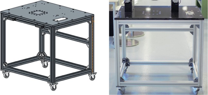
CAD detail design of the structure and its implementation
-
Axis: 3 axes (X, Y, and Z) are implemented. Y axis is mounted in a gantry setup (2 parallel and synchronized carriages) and XZ axis are orthogonal single carriage. Each axis possesses an end stop sensor which allows the machine to find a reference point in space from which each position of the tool head is calculated (homing process) (Fig. 6.7).
Fig. 6.7 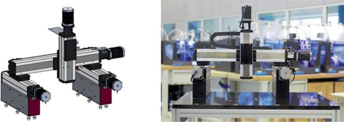
CAD detail design and the axes implementation
-
Print head: It contains the syringe and in this design, the capacity is 10 cc, but it is possible to change it to 3 cc or 5 cc. The extrusion is volumetric with a force up to 1635 N. This force will allow to apply a pressure of 10 Bars on the ink inside a 10 cc syringe. Enough to meet the expected maximum pressure. A probe sensor is included in the extruder head and its function is to create a 3D mapping of the print base doing point mapping (Fig. 6.8).
Fig. 6.8 
CAD detail design and the implementation of the printer head
-
Construction platform: It is the base on which the part will be printed. It also has interchangeable glasses to print another construction next. It is located directly over the marble to ensure flatness (Fig. 6.9).
Fig. 6.9 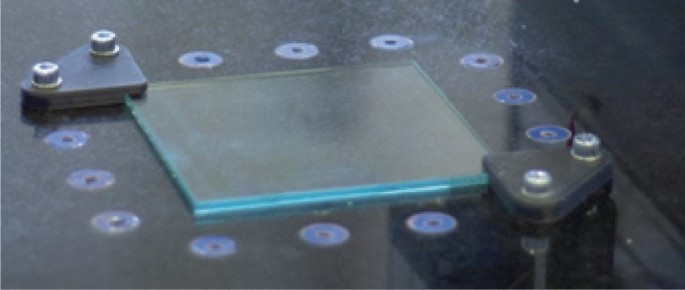
The implemented construction platform


6.3.2 Printing Process with FENIX Machine
The process to start printing is quite similar to many other 3D printers. It all starts with an idea that needs to be tangible. After a STL with the 3D object is developed it is time to elaborate the digital file called GCode, that defines mostly instructions on where to move, how fast to move and which path to follow.
Once it is ready, the DIW printing process in the Fenix machine starts. The steps to follow are:
-
1.
Turn on, enable the machine and plug in network wire to the laptop.
-
2.
Start the BLTouch mapping to allow the machine to correct bed height imperfections.
-
3.
Define Z height. It will depend every time on the size of the tip used so it is an important step to ensure the first layer is going to be well deposited.
-
4.
Weigh the syringe, load it into the shell, place them on support by screwing and add the selected tip for the print (Fig. 6.10).
Fig. 6.10 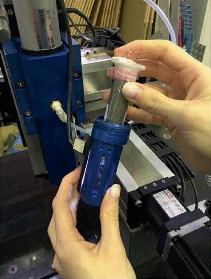
Loading syringe into the shell process
-
5.
Check ambient temperature and if it is below 22 °C degrees turn on the bed temperature.
-
6.
Extrude some material until it comes out correctly to ensure it is not dried at the tip and check the consistency of the ink. It has to be homogeneous and pasty (neither dry nor liquid) to be correctly printed.
-
7.
Finally, upload and execute the GCode of the part to print. If it is not successful, correct parameters and restart the process (Fig. 6.11).
Fig. 6.11 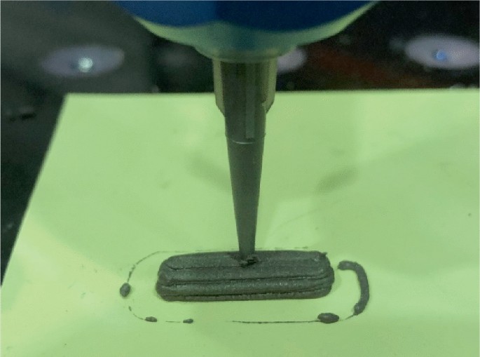
First completed printing test
-
8.
Weight the syringe once finished the print to know the quantity of the material used. Verify dimensions between the printing part and the CAD.


6.3.3 First Test Validation
The next step after the realization of the device is a series of tests in order to validate that it works correctly and meets the requirements. The validation tests have been carried out only using ink loaded with recycled material and also have 2 objectives: produce a series of samples and check the influence of temperature on the ink. For this reason, it was divided into two sub-series, without temperature control and using a hot bed.
For purposes of WP6 of the Fenix project, the same sample is printed in two different directions, short and long, in order to study the effects of the internal structure on the final part (Fig. 6.12).

Path planning of the sample with layers deposited in the long and short direction
After this whole process the piece is ready for the sinter process.
6.3.4 Sintering Process Parameters
After printing the green part, it is necessary to burn the binders and fuse the metallic particles together. This process is called sintering. The chart below shows the different sintering cycles used during different phases of the project. The objective of these tests are to observe the effect of the sintering and the different properties that can be given to the final material (Fig. 6.13).

Sintering parameters cycles
The observable effects of sintering conditions are the following (Fig. 6.14).

Effects of sintering conditions
Many parameters influence the final quality of the parts but a longer cycle (especially the isotherm part) seems to be highly beneficial for the process as it can be observed between the two monomodal tests (cycle A and B) and also bimodal inks seem to have the best density results.
6.4 Technology’s Viability
6.4.1 Applications in the Industry
CIM-UPC has printed two different use-case demonstrators with two different types of powders provided, FNX24 and FNX31, both Fe-Bi-modal.
The use cases demonstrators have been designed in order to prove the ability of the Fenix project to enter the industry with real applications and a circular process.
About the two demonstrators, one is a piece called Endstop and it is used in the machine itself to detect the end of the axis travel. The other one is a Handle useful for quick fixing with a thread on it. It has been machined after being printed. Below it is shown the printing results and the functional piece that would be replaced.
-
1.
Endstop:
See Fig. 6.15.

End-stop use-case
-
2.
Handle:
See Fig. 6.16.

Handle use-case demonstration and commercial application
Between the first tests, that were not a complex geometry, and the last ones, there have been a lot of improvements in the 3D printing process. Many printing parameters have been adjusted to the ink created. For example, the printing speed has been reduced to improve the extrusion deposition and to get more accuracy in the geometry printed. As temperature had an important role, the bed temperature was implemented and adjusted according to the ambient conditions. This made a good improvement in the ink fluency and adherence during the printing. All these improvements have a positive impact and consequently functional parts have been printed (Fig. 6.17).

Use-case demonstrator printing process
All data about printing conditions, characterizations and tests have been uploaded on ALBUS, that is Fenix platform to store data at all the stages of the circular business.
Half of these demonstrators have been sintered in Barcelona, same place where printed, and the others were sent to Italy to sinter. It is indicated in the ID of each part, with an A or a B respectively. This way it is possible to know if the travel and the time between the printing and the sintering, affects or not the final properties. Due to the hard travel conditions, the piece has to be very well packed with foam and other kinds of protections to ensure a good arrival, however, it has been observed that it is not guaranteed. However, this part is still in process waiting for the results.
CIM-UPC has also possible use-case demonstrators for copper inks, based on its main properties high thermal and electrical conductivity.
-
(i)
Heat sink: it is a passive heat exchanger made by thermal conductivity materials that dissipates the heat from a mechanical or electronic device. Cooper has perfect conditions for it, however as it is less ductile than other materials like aluminum, it is difficult and more expensive to manufacture into heat sinks in comparison with the aluminum ones. This is why DIW 3D printing can be the perfect technology to manufacture them and CIM-UPC has also printed one demonstrator for this use-case with a little more complex geometry. The ink used for the print has been FNX51, a commercial copper ink (Fig. 6.18).
Fig. 6.18 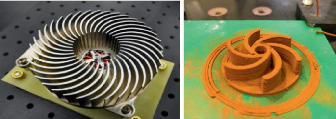
Commercial fan-less heatsink application and copper printed demonstrator
-
(ii)
Electrode connector for EDM (Electrical Discharge Machining): It is the tool-electrode for a metal fabrication process based on the use of electrical discharges. This tool requires good electrical conductivity properties and complex forms, so not only copper is a good material for it but also DIW technology is a good process to get it (Fig. 6.19).
Fig. 6.19 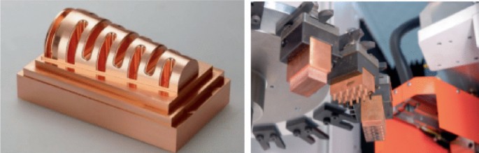
Commercial copper tool-electrode
-
(iii)
MIG Welding Nozzle: It is used to direct the gas into the weld puddle and to protect the contact tip from molten metal. Cooper is the only candidate when the process requires higher amperage. As copper has tough machining process conditions because of its softness property, DIW technology can, again, be a good alternative to manufacture them (Fig. 6.20).
Fig. 6.20 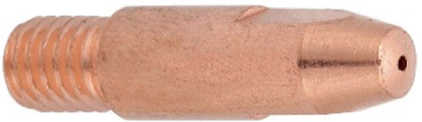
Commercial copper MIG nozzle


The last two use-case applications will be the next ones to print and test if they are viable and to test properties.
6.4.2 Applications in the Industry
Good results are linked to good part properties, with a similar density of the metal to achieve good mechanical properties. As seen before in the sintering previous section, monomodal ink samples show high porosity in the SEM (Scanning Electron microscopy) image and as a consequence, little mechanical properties. In other manufacturing processes density is increased by adding some pressure to the mold but in 3D printing this is not a possible method. Even though there are other methods, in this case, changing the distribution of the particles in the ink is the optimal one.
To do so, not only sintering parameters have been modified but also bimodal powders are developed, called FNX24 and FNX31. The main particle has a size of 82 µm and the next has around 12 µm for FNX24 and a size of 81 and 15 µm for FNX31. Consequently, the little spaces are filled with the smallest ones and density increases closer to the metal (8.13 g/cm3). Thereby, powders have been modified to get the minimum porosities of the printed parts (Fig. 6.21).

FNX24 and FNX31 bimodal particle distribution
So the good results are obtained, not only for the increased density, but also for the generation of good mechanical properties.
6.5 Conclusions
To conclude this chapter, it is worth to mention different points because the additive manufacturing process involves many different aspects such as the printing process itself, the sintering post-process, the material and the whole system based on circular economy.
Starting with the printing process, the printing parameters have been correctly determined to get good quality samples. Besides, sintering has been done successfully around Europe, overcoming shipping difficulties of the parts however due to COVID-19 this system has to be re-defined considering EU lockdown. In spite of these shipping issues, the effectiveness of the sintering is confirmed by obtaining bulk metallic parts. Moreover, the optimal size of the powders has been improved and thanks to bimodal composition, printed parts get better density and mechanical properties.
Referring to the circular system, thanks to the Fenix project, a workflow plan has been developed between different partners around Europe and with it, a circular business model has been implemented successfully. It has acquired and uploaded a complete dataset called ALBUS to track the different steps in the Fenix project to close circularities.
And last but not least, DIW technology has proven to be the best suitable additive manufacturing technology to recycle WEEE by developing the demonstrators, not only with Fe-based ink but also with copper-ink, with real applications.
Reference
Peroncini, S. (2018/2019). European University market for 3D printing and business plan of an additive manufacturing laboratory (Online).
Author information
Authors and Affiliations
Corresponding author
Editor information
Editors and Affiliations
Rights and permissions
Open Access This chapter is licensed under the terms of the Creative Commons Attribution 4.0 International License (http://creativecommons.org/licenses/by/4.0/), which permits use, sharing, adaptation, distribution and reproduction in any medium or format, as long as you give appropriate credit to the original author(s) and the source, provide a link to the Creative Commons license and indicate if changes were made.
The images or other third party material in this chapter are included in the chapter's Creative Commons license, unless indicated otherwise in a credit line to the material. If material is not included in the chapter's Creative Commons license and your intended use is not permitted by statutory regulation or exceeds the permitted use, you will need to obtain permission directly from the copyright holder.
Copyright information
© 2021 The Author(s)
About this chapter

Cite this chapter
Poudelet, L., Castellví, A., Calvo, L. (2021). An Innovative (DIW-Based) Additive Manufacturing Process. In: Rosa, P., Terzi, S. (eds) New Business Models for the Reuse of Secondary Resources from WEEEs. SpringerBriefs in Applied Sciences and Technology(). Springer, Cham. https://doi.org/10.1007/978-3-030-74886-9_6
Download citation
DOI: https://doi.org/10.1007/978-3-030-74886-9_6
Published:
Publisher Name: Springer, Cham
Print ISBN: 978-3-030-74885-2
Online ISBN: 978-3-030-74886-9
eBook Packages: EngineeringEngineering (R0)