
Abstract
Within FENIX a set of three use cases has been developed in order to test in practice the selected business models. After the description of a common data repository virtually connecting all the use cases and describing the common step of PCB disassembly, this chapter presents each use case into detail, by evidencing the main findings.
You have full access to this open access chapter, Download chapter PDF
10.1 Introduction
FENIX links together different production steps with the final goal to effectively re-introduce in the market the material recycled from wastes if electrical and electronic equipment. This chapter describes the work done for the technological validation of the pilot manufacturing lines networked together, to validate the links between them: assembly/disassembly process, hydrometallurgical process, High Energy Ball Milling (HEBM), feedstock formulation and 3D additive manufacturing. Different material has been tested also to identify the most effective cooperation and the results applied to support the definition of new business models. Three use cases have been considered for the validation of the net-worked activities of the plant: the direct use of the recovered PM by additive manufacturing (Use Case 2), the valorization of the by-product of PM recovery in form of metal powders for Additive Manufacturing via Robocasting and in form filament for Additive Manufacturing via Fused Filament Fabrication. For each use case several iterations of between the networked plant have been performed to identify optimization points and to collect da-ta on the networked plant that can be utilized for Business Development, Life Cycle Performance Assessment, and circular supply chain digitalization. The combination of the three use cases offers also interesting datapoints to evaluate the efficacy of a circular business based on multiple streams of activities (Fig. 10.1).

Process chain for the three FENIX use cases
10.2 Albus, the Data Repository of FENIX
The Use cases have defined a unique repository for the data generated during the validation, and in particular characterizing the batches delivered within the consortium. This platform, named internally Al-bus, consists in a space online in which pictures, analysis, processing data, identification codes are uploaded. Albus is the primary source of data for the validation of the business cases and the evaluation of the benefits of the Decision Support System to the whole business cases. The batch identification system that has been put in place allows to track the evolution of a component, even a specific phone from grave to cradle as a new product. Each step in the value chain has a defined input and output batch, as well as a defined set of information that characterize the batch. For example, the batches of dismantled WEEE components are provided with information about WEEE class, Component type, Nominal value €/kg, Quantities but also processing time and effort. The adoption of Albus gave the possibility to create a Data flow along with the Material flow that helped in the understanding and quantification of the business opportunity (Fig. 10.2).

Material and data flows in FENIX
10.3 Collection and Dismantling, the Conventional Approach
The initial steps in the value chain are similar, regardless the down-stream activities afterward. The first step in the networked pilot plant consists in the collection of WEEE to be recycled. For the first set of tests performed on the pi-lot plant, GREENTRONICS collected a quantity of 12.2 tons of electrical and electronic waste (WEEE), PCs and laptops mainly. The WEEE entered the normal treatment flow, respectively manual dismantling and sorting by types of fractions (electronic boards, iron, aluminum, coolers, power supplies, plastics, etc.). The fraction that was of interest in the first set of tests was the waste printed circuit board (WPCB), category 1. Thus, after the first treatment phase resulted in a quantity of 1 ton of WPCB category 1A. In the second treatment phase, the WPCBs were depolluted according to the UNIVAQ specifications. The following components were manually removed: batteries, electronic capacitors, heat sinks, connectors, quartz resonators, inductors, black panels, and multilayer and Ta capacitors. In the end, a quantity of 502 kg of cleaned WPCB resulted. In the last treatment phase, the WPCBs were ground in a professional shredding machine in 0.50–3.00 cm particles (Fig. 10.3).

WEEE collected and shredded for recycling at the Hydrometallurgical Plant
Other batches for recycling tests have been collected, varying com-ponents existing on the WPCB: components rich in rare earths and rich in precious metals. GREENTRONICS collected the same amount of WEEE and went through the same treatment phases, except for the shredding part of WPCB. A quantity of 43,735 kg of cleaned WPCB resulted.
To fully assess the potential of the hydrometallurgical plant, and the downstream metal valorization, components with a high content of precious metals (gold, silver) has been also collected. GREENTRONICS proceeded to a more detailed dismantling of the motherboards, extracting from them the RAM memories and CPUs. To collect 25 kg of such selected components, GREENTRONICS processed an amount of 1060 t of WEEE. In the first stage WEEE was manually disassembled, in fractions (electronic boards, iron, aluminum, coolers, power supplies, plastics, etc.), and then, in the second stage, we manually extracted CPUs and RAMs from the electronic boards. Detailed disassembly reports have been collected and uploaded into the platform Albus, to facilitate the evaluation of the LCPA and business figures.
10.4 Semi-Automated Disassembly, an Innovative Approach
A semi-automated PCB disassembly station, set up by POLIMI, was used as platform to evaluate the impact of mechanized disassembly in the business scenarios of FENIX and as glimpse of what could be a fully mechanized system form the point of view of data analysis, process optimization and business digitalization. Considering both the same process and the same equipment, a dataset has been implemented based on disassembly tests done on more than 50 PCBs previously extracted from WEEEs by GREEN operators and sent to POLIMI for a further disassembly. These PCBs came from disposed cellular phones. The “Albus” platform has been populated with several pieces of information to create a logical (and continuous) information flow among the different pilots. The data gathered by POLIMI do not have a practical value because of the low performance of the presented process compared with existing industry-oriented ones. Instead, it must be intended as a tentative to link the developed PCB disassembly process with the other pilots (Fig. 10.4).

A semi-automated disassembly station
The data gathered during the PCB desoldering process can be divided into two parts: data gathered from the cobot and data gathered from the operator. The need for two different data sources comes from the difference in data origin. The data coming from the operator are related to the physical properties and characteristics of the PCB while the data generated by the cobot are related to the automated process. Further sources of data have been considered to increase the efficiency of the data gathering process:
-
The introduction of a digital load cell under the PCB fixture to en-able automatic weight measurement of the PCB before and after desoldering.
-
The addition of a power measurement system capable of logging data directly into MQTT.
-
The use of real time data to automatically identify the phase of the process being performed and tag the data with this information to add more knowledge on the process and on its sustainability.
-
The exploitation of a cobot-assisted process just for the desoldering of both valuable and already functioning components from PCBs that could be, eventually, re-sold into the market as secondary spare parts.
10.5 Use Case 1: Green Metal Powders for Additive Manufacturing
The new Robocasting machine has been designed to use feedstock composed of advanced metal powder formed with non-precious metals recovered from electronic waste. The machine can manufacture metal parts by additive and this enables FENIX to target a new segment of the AM market which has substantial growth potential over the next few years. This use case involves most of the plants developed in FENIX: Electronic wastes are treated via a Hydrometallurgical process to ex-tract precious metals, in which the resulting leachate is still rich in metals such as Copper that is collected and valorised. The copper is collected by electrowinning and mechanically alloyed with primary metals to form a new metal alloy. This powder is com-pounded with hydrogels to form an ink and is packed in syringes to be used by the dedicated DIW machine. The part realized with this AM technique can be afterward treated in a furnace to remove the hydro-gel additives in a first step and to sinter the part in a solid metal afterward (Fig. 10.5).

Material evolution between the different processing steps
The setup of the different production units and the parameters of the process involved have been adjusted to the specific requirements of this use case, from step 3 onward. From the interactions between the production steps useful information have been retrieved on the aspects of the business, both from the technical point, i.e. most effective parameters and procedures, and the commercial point, i.e. manufacturing lead time, costs etc. For this use case the main hydrometallurgical process utilized has been the GoldRec1, the plant was built to work following multiple pathways and differentiating between the use cases was useful to test the re-configurability of the networked plants (Fig. 10.6).

FENIX hydrometallurgical plant: 3D view, in red highlighted the components used both in Gold-Rec 1 and 2, in green the equipment for electrowinning used exclusively for GoldRec1
As explained in Chap. 5, the GoldRec1 final step consist in the electrowinning process, and this determine the specific challenge for USE CASE 1: the optimization of a Copper resulting from electrowinning of the residual solution from the recovery of the much valuable Au and Ag. The metal obtained as it is, find scarce if no use due the high oxygen level and the heterogeneous morphology of the particles, that makes it not competitive in the market if not further processed by casting or atomization. MBN applied its mechanical alloying route to this upcycling task, processing the copper to reduce the oxide content and integrating it in a new alloy suitable for additive manufacturing processes that involves a final sintering step (Fig. 10.7).

Upcycling steps for copper powder
In step 1, to provide consistent data on the powder characterization, the powder had to be homogenized, this step is anyway required to make the powder suitable for the mechanical alloying process with the MBN’s plant. It is important that the powder resizing does not substantially affect the material properties, such as composition, microstructure, and homogeneity of phases distribution. Different process energy levels were therefore tested before considering acceptable the resulting powder (Fig. 10.8).

As received copper—Obtained from electrodeposition
Step 2 is crucial step before processing of recycled Copper is to characterize it, to assess its actual metal composition and to quantify the presence of copper oxides. Visual inspection can reveal that the recycled Copper presents a wide morphological range, that is directly related to the electrowinning process. The copper adhering directly to the cathode appears in the form of scales and foils also in the centimeter range, while copper deposited on top of this layer resulted in a fine powder, once scraped from the cathode (Fig. 10.9).

XRD analysis of the recycled copper
For a quantitative assessment of the composition, MBN deployed different techniques, in particular SEM/EDX to identify the actual composition in metals, LECO analysis to precisely quantify Oxygen, and Carbon trapped in the powder and XRF that is complementary to but have advantages in the sample preparation and response speed (Fig. 10.10).

Different morphologies of the recycled copper from electrowinning
In step 3 a reduction of Copper powder is required to decrease further the presence of oxygen in the recycled powder. The amount of oxygen can be optimized in the recycling step and during electrowinning, but it is difficult to eliminate. The key to re-move the oxygen is to realize the process in an Ar/H2 atmosphere, the powder is put into a furnace and kept at moderate temperatures, to prevent sintering of the powder °C for time ranging from 120 to 180 min. The powder obtained has been further analyzed to assess oxygen evolution and determine the process condition in function of the oxy-gen level.
In step 4 Copper have been alloyed with other elements to obtain a new metal powder to be used in additive manufacturing. Mechanical Alloying (MA) is a solid-state powder processing technique that involves repeated cold welding, fracturing, and re-welding of powder particles in a high-energy ball mill. Mechanical Alloying has been used also to exploit the possibility to adapt to batch-to-batch variations, possibility due to different WEEE batches, and the possibility to substitute Copper in multiple alloys, that might better tolerate a not completely purified copper powder. The use of recycled copper required to develop new processing parameters and methods to improve the morphological characteristics of the material, especially to make it suitable to produce inks for Robocasting (Figs. 10.11 and 10.12).

SEM images in backscattering of section of alloyed powder

Sintering trials from powder with different morphologies
The use of recycled Copper has been assessed to evaluate the im-pact of the oxygen content in the final sintering behavior of the pow-der. To this end free sintering trials on the powder, obtained with different conditions, have been performed resulting in a good behavior of the sintering also substituting completely the copper in the formulation with recycled copper. Moreover, the proper use of post processing techniques to select the right particle distribution allowed to obtain densities in the sintered bulk that are comparable with those on a reference powder obtained from pristine metal powder.
The results obtained with the use of recycled Copper from electrowinning encouraged testing its optimization also as pure copper powder. To produce pure copper powder, a dedicated processing equipment have been used. Pre-conditioning of the equipment for mechanical alloying has been done using pure commercial copper obtaining a homogeneous lining that is continuously renovated and maintained during the process. Recycled Copper powder from electrowinning has been processed with the use of a specific Process Control Agent—PCA, to de-crease further the oxygen content. The PCA residues were afterward completely removed from the powder with a thermal treatment at low temperature (300 °C) obtaining acceptable values for residual oxygen levels (<0.5%) although the appearance of the powder resulted in affected and evidently darkened. If the AM processing aims at the commercialization of this powder, then this shortcoming must be considered (Fig. 10.13).

Post processed powder delivered for ink production and Robocasting
In step 5, the Particle Size Distribution (PSD) can be only partially con-trolled during the mechanical alloying process by using PCA and the specific process conditions. Therefore, in order to have a narrower PSD, sieves or other classification methods have to be used. After the synthesis step, powder is transferred to an air classifier to select those powder fractions (usually fine particles) that cannot be sieved. For dry materials of 100-mesh and smaller, air classification provides the most effective and efficient means for separating a product from the feed stream, for de-dusting, or, when used in conjunction with grinding equipment, for increasing productivity. Air classifiers can only be used for dry processing (Fig. 10.14).

Bimodal particle size distribution obtained with post processing
With the alloyed metal powder successfully obtained and manufactured, the next step is to formulate the appropriate composition. The formulation has been done to develop a material ink to be used through Direct Ink Writing (DIW) process. As two different Fe-based powders have been received (monomodal and bimodal), two different types of inks are obtained from the same inf formulation process. The ink must present a pseudoplastic behavior to be printable by DIW. So, it is recommended to have a solid load, i.e. metal powder content, of 35–60% to obtain a functional final part. The process is based on the mixture of the Fe-based powder with a hydrogel and a dispersant agent. The best performing ink formulation has been obtained with 25% of Pluronic acid as hydrogel and 45% by weight of powder (either monomodal or bimodal) Fe-based Monomodal powder. Dolapix PC75 has been used as dispersant agent (Fig. 10.15).

Syringe cartridge with FENIX metal ink being loaded into the shell process
After loading the cartridge and creating the Digital File with the printing parameters, it is time to start the DIW printing process in the FENIX machine. As stated in previous chapters, the need for the construction of a specific new DIW printer was necessary to cope with the high viscosity of the metal ink. Many printing parameters have been adjusted to obtain good depos-its with the ink created. The main one parameter to be adjusted was the printing speed that has been reduced to improve the extrusion deposition and to get more accuracy in the geometry printed. Temperature also has an important role, the bed temperature was monitored and adjusted according to the ambient conditions. This gave the possibility to have a good improvement in the ink flowability and adherence during the printing. All these improvements have been tested on simple geometries be-fore evaluating the final printing capability on complex and more functional objects (see Fig. 10.16).

DIW process of a complex shape
The last processing step to be evaluated to before obtaining a full metallic component is sintering the printed part, that is still in its “green” state. A selected number of printed samples in green state have been sintered and analyzed systematically to identify the better performing material and the most suitable/effective conditions that can be suggested to possible users of this technology. Once obtained sintered parts, their visual analysis with SEM is a powerful, although only indicative, evaluation of the actual densification state. To obtain a more quantitative value, that can be utilized also by the DSS, the detailed evaluation of the density has been performed on all the samples. This requires evaluating the picnometric density, in helium, that considers all the open porosities, and the Archimedean density, in water, that take into account only partially the surface roughness but not the open porosities. The internal porosity is calculated considering the theoretical value of a completely densified material (Fig. 10.17).

SEM images in section of a sintered 3D printed parts, each row is a material variant—magnification × 100
10.6 Use Case 2: 3D Printed Jewels
Use case 2 focuses on developing a new business model based on an innovative system for offering customized and personalized jewellery to customers using recycled precious metals from the FENIX waste electronics recycling process. A use case pilot is developed, which involves a prototype 3D scanning hardware and the complementary software for customizing jewels. In order to capture the human face, the FENIX team has created a prototype scanner which uses photogrammetry and controlled lighting to accurately capture the human facial geometry and has also developed an initial set of face jewellery designs in order to convert the captured facial geometry to jewels (Fig. 10.14). The purpose of the prototype 3D scanner is to act as a point of sale taking orders directly from customers and feeding them to the FENIX interconnected operations for further processing (Fig. 10.18).

Face jewelry
The business model revolves around the concept of specialized hardware that will act as a point of sale taking orders for customized and personalized jewelry from potential clients (the jewelry is 3D printed in castable resin and then cast with recycled precious metals from electronic waste). FENIX developed innovative and customized hardware and software for use case 2, subtracting detailed 3D scan of human faces, by reproducing a 3D mesh of it. Subsequently, the scanned faces will be transformed into a customizable jewelry object. In addition, a software platform will support the commercial process related to customizable face jewelry objects being ordered from each hardware installation. The 3D printing facility and distribution center that will use the recovered precious metals will be linked to this use case pilot installation and to the online platform that will process all the orders. The process developed is explained graphically in the following Fig. 10.15.
3D Scanning human faces and converting them into customized jewelry is a brand new and totally innovative concept that currently does not exist anywhere in the world. The use of precious metals recovered from the recycling of electronic waste adds further innovation to the concept and caters for branding the jewels as part of the circular economy. The FENIX Jewelry use case has the potential of a total reconfiguration of the channel landscape allowing jewelers to achieve instant sales with the onsite hardware and the online back end services that will be provided (Fig. 10.19).

The FENIX customized jewelry process
10.6.1 Description of the Involved Plants in UC2
Electronic Waste collected and dismantled by GREENTRONIC and POLIMI are processed via Hydrometallurgical route to recover precious metals by UNIVAQ at the plant installed within LoRusso Estrazioni. The precious metal is then melted and converted to jewelry by I3DU and 3DHUB by using lost wax casting in combination with 3D printing (Fig. 10.20).

Plants involved in UC2
All the data collected in every step of the production chain are registered and stored in ALBUS, that is the data repository platform for FENIX developed to host the different data sources and to allow linking the batches from WEEE to precious metal.
10.6.2 Metal Recovery
The GOLD-REC 2 hydrometallurgical process (Fig. 10.17), process that was previously developed by UNIVAQ and patented by University of L’Aquila, was applied on grinded RAM modules, PCBs of mobile phones and ceramic CPUs of desktop computer. An important advantage of this process is represented by the fact that it can be performed on the entirely waste material without a preliminary crushing (Fig. 10.21).

GoldRec2 process flowsheet
The process was tested within the Fenix hydrometallurgical plant (Fig. 10.18) and it consists in solubilization of both base and precious metals content of wastes using the HCl-H2O2-C2H4O2-H2O leaching system (Fig. 10.22).

FENIX hydrometallurgical plant—3D view
In brief, the plants involved and their relation to use case two are the following (Table 10.1).
10.6.3 3D Scanning
For the scanning of the human face in 3D and converting the facial characteristics into a usable 3D mesh, several available 3D scanning technologies were originally reviewed. In order to conclude which 3D scanning technology would be the most suitable for the specific application of 3D scanning the human face the following three criteria were considered as the most important:
-
Speed. A person face is not a static element and is a constantly moving object that cannot hold still for long periods of time waiting to be scanned, so the scan process needs to be either instantaneous or fast.
-
Accuracy. The resulting 3D scan geometry must be accurate enough so when the jewel is created the human face is still recognisable and the person can identify the facial characteristics on a small scale.
-
Non-Intrusive. The scan process and underlying technology needs to be non-intrusive for humans.
Of all the reviewed technologies it was concluded that the most suitable one to be used for the application is photogrammetry as it offers the highest speed (click of a button) and is the least intrusive and most familiar one for humans (i.e. it is just cameras photographing the face) (Table 10.2).
For the photogrammetry based scanner that was developed several design variations were designed and several iteration loops were necessary in order to find the optimum angle for the 15 cameras so that there is sufficient camera focal view overlap for photogrammetry to have good results and to be able to create a 3D mesh of the face with sufficient quality for being 3D printed and casted in precious metals (i.e. 15 images of the face taken from different horizontal and vertical angles so that there is more than 20% overlap from image to image).
After the initial prototyping phase, further development of specialized hardware for 3D Scanning of the human face with a more detailed and refined industrial design that looks more like a finished product took place. The most ergonomic and aesthetically nice design was selected as being the best candidate and was further developed into a detailed design. Below are some renders on the final design selected which was the basis for developing the final prototype of the 3D scanner (Fig. 10.23).

Final detail of 3D scanner design
That design was also prototyped and constructed using 3D printing (Fig. 10.24).

Final 3D scanner design prototype
In parallel with the development of the scanner, development of custom software/firmware for controlling the cameras and picture capture as well as the luminosity from the LED lights took place. The firmware was designed to be able to provide a GUI to the operator enabling them to:
-
Control the lighting by adjusting the luminosity of the led lights.
-
Control basic image capture properties (brightness, contrast saturation etc.).
-
Fully synchronize the image capture so that all 15 images are captured at the exact same instance.
Apart from developing the firmware a more advanced user interface has also been designed. This user interface will be the main interface that the users will interact with while using the scanner allowing them to 3D scan their face and select and order different custom-made jewelry with their own face in 3D.
10.6.4 Wax Printing and Lost-Wax Casting
Once the human face is captured by the 3D scanner and is fused into the custom jewellery, the production of the jewel can begin. The wax printing and Lost-wax Casting manufacturing process starts by 3D printing the model in wax or castable resin. This step is a type of Stereolithography that uses a wax-like resin. Next, one or more wax sprues will be attached to the model. Then the model will be attached by the sprue to a wax ‘tree’, together with several other models. The tree is then placed in a flask and covered in a fine plaster. When the plaster solidifies, it forms the mould for casting the metal. The plaster mould is then put in an oven and heated for several hours to a point where the wax is completely burned out.
Next, molten metal is poured in to fill the cavities left by the wax. Once the metal has cooled and solidified, the plaster mould is broken, and the metal models are removed by hand. Finally, the model is filed and sanded to get rid of the sprues. It will be sanded, polished or sandblasted to create the finish desired by the customer (i.e. the cutting-edge technology of 3D printing meets the ancient technique of metal casting!). The upside of casting the model is that the final product will have the best quality: surfaces will be smooth, and the strength, feel, and look of precious metals (e.g. a silver ring or a gold pendant) is exactly what a customer would expect.
10.7 Use Case 3: Advanced Filaments
FENIX linked together different production steps to get advanced filaments for 3D printing using non-precious metals recovered from electronic waste. The metal/polymer filaments can be used in fused filament fabrication (FFF otherwise also known as FDM) to produce metal parts. The development of this feedstock enables the overall FENIX business system to target the prosumer segment of the market which has substantial growth potential over the next years. Like in the other Use Cases, Electronic Wastes are processed via Hydrometallurgical route to remove precious metals, the resulting leachate is still rich in metal such as Copper and Tin that are collected and valorised. The metal mixture obtained after precipitation and calcination is mechanically alloyed with primary metals to form an advanced metal alloy developed to be easily and effectively sintered. The resulting powder is compounded with polymer and additives and extruded in filaments rich in metal (<80 wt%) that can be printed by FFF resulting in a green compound. Debinding and sintering of the resulting part leads to the formation of a 3D printed metal component. The data and results gathered in Albus during the validation of the use case, contributed to the overall assessment of the activities (Fig. 10.25).

Process and material involved in use case 3
This use case is based on the valorization of the by-product form the recovery of Precious Metals with the GoldRec2 approach, these metals consist mainly in Copper Tin and Iron. The details on the processing steps related to the recovery of precious metal are reported in the previous chapter, while the specific part related to UC3 consists in the final cementation of both Cu and Sn with iron metal powder. This powder mixture, as it is, finds scarce if no use due the mixed and variable composition that can also change at each batch of recovery. Mechanical Alloying (MA) was applied in the networked pilot activities to upcycle this metal mix by-product to make it suitable to be used as starting material for other manufacturing routes. During MA, the recycled powder was alloyed with pristine elements to compensate the composition of the recycled metal powder, targeting the production of an alloy suitable for additive manufacturing processes that involve a sintering step. The activities performed in MBN for the powder up-cycling were divided in several steps, going from initial powder analysis to the final granulation that produces a pre-compounded mixture ready to use in AM-feedstock filament production. Already from visual inspection, the recycled powder seams to not suffer much from oxidation, thanks to the calcination step, further analysis confirmed that it can be used directly along with the other commercial raw powder in the MA process. A more detailed analysis at the SEM reveals that the amounts of tiny particles, below few microns, is not negligible, and this might cause problems connected with dustiness, that can hinder a direct commercialization of the recycled powder. The processing steps, as those done in MBN, solve this issue mechanical, by alloying the powder in a new product (Fig. 10.26).

SEM images of the recycled powder mixture
The composition of the recovered powder can vary from batch to batch, according to the hydrometallurgical process parameters, with the composition of the starting WEEE and the efficiency of the process. Therefore, the main initial step in the precise evaluation of the powder mixture is to assess its actual metal composition (Fig. 10.27).

Benchmark of EDX and XRF results on the recycled powder mixture, on the left the portable XRF scanner used for the analysis
Given the concordance of the data achieved with the two techniques, that is within the respective instrumental errors, and considering that XRF can be directly performed on the powder without sample preparation, this latter was chosen to perform the verification of the batches to verify the metal content and determine the mixture of commercial powder and recycled powder in the mechanical alloying process. The powder must be weighed carefully to respect the weight ratio between the different elements. To improve the alloying process, the powder is mixed to start from an already good dispersion of the primary and recycled element. This operation is normally performed also with commercial raw materials, and it is facilitated by the fact that they are purchased all with similar particle size ranges that in general do not contain a significant amount of very small particles. Using the recycled powder metal mix from calcination made this step more challenging, the amount of very fine particles tends to increase the difficulty of an effective dispersion. To overcome this, different approaches have been effectively adopted, one using a dedicated V shape blender, the other using custom made tapered tank for tumbling. Once properly dispersed the powder is introduced in the Mechanical Alloying plant. The processing condition had been optimized to get a dispersion of the elements while maximizing the yield of particles in the fraction between 10 and 60 µm, leaving to the post-processing activities the optimization of the morphology and the yield (Fig. 10.28).

Evolution of particle size distribution obtained with different processing conditions
10.7.1 Granulation, Compounding and Extrusion
The first batches of powder were directly tested for compounding with polymer, but they were not processable because of the high viscosity generated during the mix. Decreasing the metal content in the compound is not a viable solution since it has to be the highest possible, above 80 wt%, to have chances to be successfully sintered in a metal component at the end. Therefore, to overcome this problem MBN deployed its experience in powder agglomeration to provide a pre-compounded product that consist in the alloyed metal powder, mixed with a small amount of binder and additives. Different batches have been produced considering the possible combination of binder, in particular:
-
(M) Masterbatch powder is formulated to be compounded with more polymer in the extruder, example are the powders with Polyethylene Wax and Stearic Acid for which High density polyethylene (HDPE) is added to make the filament
-
(F) Production of Final composition has been tried with Acrylic res-in, this was meant to be directly extrudable to make a filament
-
(S) Granulated powder for Solvent Debinding, where wax is used and must be partially removed with apolar solvents before sintering
-
(W) Granulated powder for Water debinding, where glycols are used and must be partially removed with hot water before sintering (Fig. 10.29).
Fig. 10.29 
Scheme of the different granulated powder developed for compounding

The specific extruder utilized to obtain the filament is a “Desktop” grade one. Although the company suggests a maximum filler percentage of 30%, it has been used for processing filled polymers with a filler percentage more than 80%. At this level of filler percentage, the raw materials must be either in powder form or pre-compounded, with the latter being preferable. The ability to process highly field polymers derives from the pineapple—shaped screw. Most of the materials examined were not plastic enough when heat-ed near the melt temperature. That behavior resulted in filament separation when dragged from the puller, restricting the effectiveness of the specific mechanism. In order to solve that issue, the puller’s linear velocity should match the filament’s one as it leaves the nozzle. Since the installed nozzle had a diameter of 4.0 mm, it was not possible to reduce the filament’s diameter if the linear speeds of the pulley and the filament were the same. The solution given was to change the nozzle and install a new one with a diameter of 2.0 mm. That decision was a critical one since it proved to be the game changer for producing high filled filaments with the specific extruder. The most effective combination of metal powder, polymeric binder and lubricant resulted to be the mixture with High Density Polyethylene, Polyethylene Glycol and Stearic Acid (Fig. 10.30).

Extrusion trials of HDPE based filament at different screw rotational speeds and temperatures
Once identified the correct extruding parameters the dimensional accuracy was excellent, with the automated extruder function working perfect except when the flow became unstable.
10.7.2 Printing of the Metal/polymer Filaments Developed from Recycled WEEE
An entry level 3D printer was used to test the printability of the produced filaments. Small square specimens with dimension 20 × 20 × 3 mm were printed. The small size was chosen in order to be easier to investigate debinding and sintering process parameters. Since it was known that a larger nozzle was necessary to avoid clogs, the in-stalled 0.4 mm was replaced with a 0.6 mm one. Although the filaments were fragile, through the developed custom filament holder it was possible to feed them to the printing head without issues. The parame-ters tested were the following:
-
1.
Printing head temperature.
-
2.
Bed adhesion.
-
3.
Bed temperature.
-
4.
Print speed.
-
5.
Infill type.
-
6.
Mass flow.
Printing head temperature is one of the most significant parameters since it affects the liquification of the material, thus the viscosity which in turn affects the material flow. Incorrect temperature setting can cause sporadic clogs and textured top surfaces. The initial testing temperature was 180 °C, but it was concluded that a printing temperature of 186 °C produced the best printing results, as it is presented in the Fig. 10.31.

Effect of the printing head temperature on the top surface quality
HDPE is well known for being a very difficult-to-print material since it has a large coefficient of thermal expansion and distorts a lot during the printing process and after printing, during cooling. A good printing bed adhesion is necessary for a successful print. Three substrates were tested, glass plate, PEI sheet and packaging tape. The first two had no success, the printing part was not sticking on these surfaces. The best solution proved to be the packaging tape which in fact is PE. Also, in order to reduce wrapping and distortion during printing, the printing table must be heated as high as possible. During our testing, a temperature of 100 °C was sufficient for these small parts. For larger parts, a warmer setting is advised. Print speed is another parameter that affects the quality of the print-ed object. In the tested case, it was more than obvious that the material itself does not allow fast printings. The initial test speed was 30 mm/s and the optimized one was 13 mm/s. Different printing path were also tested to minimize the presence of voids that would hamper the final sintering step. Although the part with the concentric infill type was heavier, the weight did not match the calculated one considering part dimensions and material composition which should be approximately 3.52 gr. Part porosity is the reason for this issue, and it can be reduced by increasing material flow. After conducting several prints with different material flow coefficients, an increase of about 20% produced acceptable results (Fig. 10.32).

Custom spool/ filament holder to use the filament in a Zortrax M200 3D printer
10.7.3 Debinding and Sintering of the Final Metal Part
The setup used for debinding the printed pars is showed in below, a balloon filled with the solvent and containing the samples were kept in a in a thermostated bath for the duration of the debinding. A condenser on top prevents the leaking of fumes, and the whole test has been performed in a fume hood (Fig. 10.33).

Equipment for solvent debinding
The objective of the debinding trials were to:
-
1.
Identify the conditions for a complete removal of the PEG from the sample.
-
2.
Minimise the debinding effort, aiming to ease the process for an end-user.
-
3.
Minimise the risk deriving from using organic solvents (Fig. 10.34).
Fig. 10.34 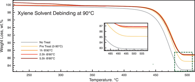
Thermal degradation profile of printed samples debinded in Xylene at 90 °C

Hexane, Cyclohexane and Xylene have been tested, at room temperature and at near to boiling temperature, the best performing process resulted to be with Xylene that also at RT gave better results than the other two. The better performance with Xylene is mostly due with the higher temperature that can be reached in the thermostated bath, thanks to the higher boiling point of Xylene. The sintering cycle has been performed in a tubular furnace, keeping a flow of a gas mixture of Hydrogen and Argon (10% H2) to facilitate binder removal and with the use of Titanium powder as hydrogen Getters. The process is like the one adopted for the sample print-ed via Robocasting in Use Case 1, with the use of alumina sand to prevent distortion of the sample during the thermal process (Fig. 10.35).

Thermal profile used in the furnace, on the left the sample container with alumina powder
On the best sintered samples it was possible to measure the hard-ness, that is indicative of the overall mechanical properties of the specimen. The results are positive and confirming the targeted hard-ness value expected for this alloy. In figure below are also reported the indicative hardness values of Steel and Titanium, where Fenix material can compare. It has been compared with annealed metals since the thermal process, and the following slow cooling, is comparable with an annealing process (Fig. 10.36).

Vickers Hardness measured on different points in the sintered samples, compared with standard materials
The measurement of other mechanical properties, such as tensile strength and Young Modulus, is strongly affected by the printing parameters and is highly anisotropic.
10.8 Conclusions
10.8.1 Use Case 1 Conclusions
Affordability
To understand whether a DIW Technology is affordable or not, it must be compared with other processes that could manufacture the same product quality and the best candidate to compare DIW is Selective Laser Melting.
Selective Laser Melting (SLM), also known as direct metal laser melting, is an additive manufacturing technology that uses a power la-ser to melt and fuse powder that is commonly metal material.
Even though SLM has more geometry options with less design limits, both have in common the possibility of adjusting the desired infill and modifying the geometry until it is optimized.
SLM uses layers from 30 to 50 µm thick and DIW layers thickness are between 0.3 and 0.5 mm. In comparison, DIW has the worst surface finish but both need post processing so at the end, this fact is not determinant.
The processes are different, but it is easy to distinguish that DIW has a really simple process compared with SLM, that has to have perfect laser system adjustments.
And finally, DIW has cheaper machine costs. It is around 20.000 and 25.000€ meanwhile SLM is much more expensive and not yet available in the same price target.
The availability of the powder from FENIX processes makes metal printing technology available to a wider range of possible user, that can exploit recycled metal powders as well as standard metal powders.
Main Results:
-
If the powder from the recovery plant is meant to be directly sold as a product, a comminution step for homogenization should be considered.
-
The connection in a circular business with a powder processing industry such as MBN, waive the need of a powder comminution at the powder recovery plant.
-
Recycled Copper after electrowinning require homogenization and oxygen removal treatment to be considered close to market reference.
-
The copper obtained from GoldRec1 is almost pure, it does not contain other metals, the characterization procedures can be reliably performed with only XRF and LECO.
-
A processing route for the inclusion of recycled copper powder obtained by electrowinning in the new formulation has been defined and utilised to produce Iron based alloy.
-
The oxygen level can be reduced but in copper-based powder, solely composed by recycled Copper, this still affect the powder appearance.
-
Different solutions have been found to maximise the efficiency of the links between the plants, saving cost and effort in overall production route.
Although the networked pilots can be identified with the production of metal powders, there are more services and products to be considered as exploitable result of the activities, here a list:
-
Hydrometallurgical Plant—as product (the plant itself) or as a service for recover of gold and metal powders.
-
The powder from recovered metals—as a product to be used for the formulation of inks (also available from FENIX Marketplace).
-
The powder from recovered metals—as a product to be used for direct laser sintering in AM (soon available at the FENIX Marketplace).
-
Inks and DIW Printers—as a combination of product (he printer) and service (the ink) to be used as affordable additive manufacturing platform to produce parts that can be sintered into metal components (available from FENIX Marketplace).
-
Metal Parts AM—as a service, to realize metal parts from CAD design provided by the user (also available in the dedicated section ‘’Customer Generated Content’’ in FENIX Marketplace).
10.8.2 Use Case 2 Conclusions
The activities performed in the FENIX use case 2 succeed in demonstrating the technical feasibility at relevant industrial scale of the circular business models, by delivering products (raw precious metals) that can be utilized in the jewellery industry. This resulted from iteration throughout all the networked plants, from WEEE collection to jewellery realization, trying different approaches to get the most from the networked pilots.
Although the networked pilots can be identified with the jewellery production, there are more services and products to be considered as exploitable result of the activities, here a list:
-
Hydrometallurgical Plant—as product (the plant itself) or as a service for recovery of gold and other precious metals, already working in collaboration with a possible customer, LoRusso Estrazioni
-
The 3D Scanner—as a product or as a service, to enable retailers to offer new highly personalized, cutting edge, innovative and green jewellery to their clients.
-
The 3D printing facility as a service to jewellers who are selling FENIX jewellery.
10.8.3 Use Case 3 Conclusions
Different solutions have been found to maximize the efficiency of the links between the plants, saving cost and effort in overall production route in view of an integrated circular business. As example:
-
XRF characterization agrees with the EDX and is preferred to determine actual composition of each batch of recycled powder before the alloying process.
-
The analysis performed in this stage before alloying, that are unavoidable to correctly address the following alloying process, can substitute the characterization step after calcination, saving time/effort in the whole networked pilot.
-
The calcinated powder have to be managed carefully for its dustiness, all its handling needs to be performed with correct PPE and/or suction benches.
-
The hardware used is scalable, allowing to readily process batches from 20 to 100 kg/day.
-
Power post processing has been effective in increasing the overall yield of the powder in the suitable range.
-
The Particle Size Distribution has been optimized differently than the material for Use Case One since the granulation and com-pounding process are negatively affected by the increase of surface area associated with bimodal distribution.
-
Production method for granulation based on Polyethylene has been chosen among as the most effective one for filament production.
Although the networked pilots can be identified with the filament production, there are more services and products to be considered as exploitable result of the activities, here a list:
-
Pre-Compounded powder—as a product to be used for the formulation of filament or for the direct use in injection molding (also available from FENIX Marketplace).
-
Metal/Polymer filament—as a product to be used with commercial FFF and FDM additive manufacturing platform for the pro-duction of parts that can be debinded and sintered into metal components (available from FENIX Marketplace).
-
Metal Parts AM—as a service, to realize metal parts from CAD design provided by the user.
The results obtained during the activities performed are not limited to the one listed above, the other results, that con not be directly exploited relate to the setup of ALBUS, the development of DSS models for identifying correlations processes in all the networked plants, the mechanical alloying of mixed powders from direct cementation.
Author information
Authors and Affiliations
Corresponding author
Editor information
Editors and Affiliations
Rights and permissions
Open Access This chapter is licensed under the terms of the Creative Commons Attribution 4.0 International License (http://creativecommons.org/licenses/by/4.0/), which permits use, sharing, adaptation, distribution and reproduction in any medium or format, as long as you give appropriate credit to the original author(s) and the source, provide a link to the Creative Commons license and indicate if changes were made.
The images or other third party material in this chapter are included in the chapter's Creative Commons license, unless indicated otherwise in a credit line to the material. If material is not included in the chapter's Creative Commons license and your intended use is not permitted by statutory regulation or exceeds the permitted use, you will need to obtain permission directly from the copyright holder.
Copyright information
© 2021 The Author(s)
About this chapter

Cite this chapter
Bianchin, A., Smyrnakis, G. (2021). Recycling and Upcycling: FENIX Validation on Three Use Cases. In: Rosa, P., Terzi, S. (eds) New Business Models for the Reuse of Secondary Resources from WEEEs. SpringerBriefs in Applied Sciences and Technology(). Springer, Cham. https://doi.org/10.1007/978-3-030-74886-9_10
Download citation
DOI: https://doi.org/10.1007/978-3-030-74886-9_10
Published:
Publisher Name: Springer, Cham
Print ISBN: 978-3-030-74885-2
Online ISBN: 978-3-030-74886-9
eBook Packages: EngineeringEngineering (R0)