
Abstract
Assuming S.PSS applied to DE is an opportunity for a locally based sustainability for all, as introduced in this volume, we envision a new role for designers: Designing Sustainable Product-Service Systems applied to Distributed Economies, or shortly System Design for Sustainability for All (SD4SA).
You have full access to this open access chapter, Download chapter PDF
1 General Considerations for Conceptual Integration into the Design Process
Assuming S.PSS applied to DE is an opportunity for a locally based sustainability for all, as introduced in this volume, we envision a new role for designers:
Designing Sustainable Product-Service Systems applied to Distributed Economies, or shortly System Design for Sustainability for All (SD4SA).
To introduce this topic, the following preliminary definition could be given to articulate the new potential of such design:
System Design for Sustainability for All (SD4SA):
design of S.PSS applied to DE, i.e. the design of Systems of Products and Services that are together able to fulfil a particular customer demand (deliver a “unit of satisfaction”), within the Distributed Economies paradigm; based on the design of innovative interactions among locally-based stakeholders, where the ownership of the product/s and/or its life cycle responsibilities/costs remain with the provider/s, so that the provider/s continuously seek environmentally and/or socio-ethically beneficial new solutions accessible to all with economic benefits.
Within this framework a new knowledge-base and know-how emerge: competences in designing and implementing Sustainable Product-Service Systems applied to Distributed Economies, i.e. Distributed energy Generation, Distributed production of Knowledge, Distributed Software development, Distributed Manufacturing and Distributed Design.
Based on the foundations of S.PSS design [10, 6], the following approaches and skills can be identified and refined for System Design for Sustainability for All (SD4SA):
-
(a)
“Satisfaction-system” approach: This calls for skills to design the system of products and services that, within a DE paradigm, can satisfy a particular demand (“satisfaction unit”);
-
(b)
“Stakeholder configuration” approach: This calls for skills to design the stakeholders’ interactions in a particular DE satisfaction-system;
-
(c)
“System sustainability4all” approach: This calls for skills to design-for-all a DE system where the providers continuously seek environmental and/or socio-ethical beneficial new solutions, with economic benefits.
This new role in SDS4A calls for the design of “appropriate stakeholder configurations” and favouring the design of “appropriate technologies”, to address S.PSS applied to DE. In this framework, two key approaches have been merged, redefined and updated: Product-Service System Design for Sustainability and Distributed Economies (DE) design. Other disciplines that are not explicitly mentioned here could and should also be included, to contribute to a comprehensive and complete research base, e.g. Social Entrepreneurship for Sustainable Development and System Innovation for Sustainability.
2 A Reference Model of S.PSS and DE Design
2.1 Method and Tools for System Design for Sustainability for All
Criteria, method and tools
Before introducing and describing methods and tools, let us summarize the main issues discussed so far. It has been argued that a potential role exists for design for sustainability, in promoting and facilitating innovation resulting in environmentally beneficial, economically viable and socially equitable/cohesive enterprises/initiatives offering a mix of products and services, especially when applying the Sustainable Product-Service Systems (S.PSS) model to Distributed Economies (DE).
The first key point is the approach to design a stakeholders’ configuration, which is committed to creating and promoting innovative types of interactions and partnerships between appropriate socio-economic stakeholders of a system responding to a particular social demand (unit of satisfaction). Consequently, new skills are required from the designer, directly or as a facilitator of a design process:
-
A designer must be able to design both products and services, related to a given demand (needs and/or desires), i.e. a satisfaction unit;
-
A designer must be able to identify, promote and facilitate innovative configurations (i.e. interactions/partnerships) between and among different stakeholders (entrepreneurs, users, NGOs, institutions, etc.), i.e. a satisfaction system related to a given demand (needs and/or desires) as a satisfaction unit
The second key point emphasizes S.PSSs applied to DE innovations that are environmentally, socio-ethically and economically sustainable, i.e. they have a low environmental impact and promote socially equitable and cohesive results, with economic benefits. This underlines that the design process should be oriented towards sustainable solutions, i.e. a designer must be capable to design S.PSSs applied to DE systems (and related stakeholder interactions) that couple economic benefits with environmental and socio-ethical, beneficial new solutions. Consequently, these new skills are required from the designer:
-
The ability to orientate the system design process towards eco-efficient solutions, encompassing both environmental and economic sustainability;
-
The ability to orientate the system design process towards socio-efficient solutions encompassing both socio-ethical and economic sustainability.
In this chapter, we describe a series of tools that can be applied during different phases of a design process. Besides their specific functions, more generally, they are meant to assist the designer in accomplishing three objectives:
-
1.
Assessing existing system sustainability and defining sustainability system design priorities;
-
2.
Generating a sustainability-focused system idea and concept (innovative S.PSS applied to DE);
-
3.
Checking/visualizing the sustainability improvement/worsening of developed system concept/s (comparing the existing baseline with the new, innovative system).
Various research projects have been funded by the European Union and the United Nations Environment Programme (UNEP)Footnote 1 over the past decades to develop and test methods and tools for system design, the main ones being SusHouse,Footnote 2 ProSecCo,Footnote 3 HiCS,Footnote 4 MEPSS,Footnote 5 SusProNet,Footnote 6 LeNSFootnote 7 and LeNSes.Footnote 8
In this chapter, the Method for System Design for Sustainability (MSDS) is described, together with its tools for System Design for Sustainability for All, i.e. design of S.PSS applied to DE. It is important to note that experimentation, both in applied research projects and in teaching, has been fundamental and will continue to be so in future, in order to allow methods and tools to be assessed, adapted and improved.
2.2 MSDS: A Modular Method for System Design for Sustainability
The MSDS method aims to support and orient the entire process of system innovation development towards sustainability. It is conceived for designers and companies, but it is also appropriate for public institutions, NGOs and other types of organizations. It can be used by an individual designer or by a more extensive design team. In all cases, special attention has been paid to facilitate the co-designing processes both within the organization itself (between people from different disciplinary backgrounds) and outside, bringing different socio-economic actors and end-users into play. The method is organized in stages, processes and sub-processes. It is characterized by a flexible modular structure so that it can easily be adapted to the specific needs of designers/companies/organizations and to diverse design contexts and conditions. Its modular architecture is of particular interest in terms of the following considerations:
-
Stages/processes: all stages and related processes can be undertaken, or only some depending on the particular requirements of the project;
-
Tools: the method is accompanied by a series of tools that can be selected and deployed during the design process according to the project need;
-
Dimensions of sustainability: the method takes into consideration the three dimensions of sustainability (environmental, socio-ethical and economic). It is possible to choose which dimension(s) to operate on;
-
Integration of other tools and activities: the method is structured in such a way as to allow the inclusion of design tools that have not been specifically developed for it. It is also possible to modify existing activities or add new ones according to the particular aspects of the design project.
The basic structure of MSDS consists of four main stages:
-
1.
Strategic analysis
-
2.
Exploring opportunities
-
3.
System concept design
-
4.
System detailed design.
An additional stage can be added, across the others, for drawing up documents to report on the sustainability characteristics of the designed solution:
-
Communication.
Table 1 shows the aim and processes for each stage.
3 Tools Developed by LeNS
This section describes several tools that may be used to support the various stages of the Method for System Design for Sustainability (MSDS) with an integration of Distributed Economies (DE).Footnote 9 In general, the tools are created to support designers to achieve four objectives:
-
To assess existing systems and define sustainability design priorities;
-
To explore opportunities by generating sustainability-oriented system ideas with a specific focus on S.PSS applied to DE;
-
To visualize the proposed S.PSS and DE concept design;
-
To detail and communicate the proposed S.PSS and DE concept design by highlighting environmental, social and economic benefits.
Seven S.PSS and DE design support tools, newly developed within the LeNSin project, are presented below:
-
Sustainability Design-Orienting Scenarios (SDOS) on S.PSS and DE
-
Innovation Diagram for S.PSS and DE
-
Concept Description Form for S.PSS and DE
-
System Map for S.PSS and DE
-
S.PSS and DE Idea Borads (embedded into the SDO toolkit)
-
Strategic Analysis Toolkit (SAT) for DE for Socio-Economic Ecosystems (SEE)
-
Distributed Manufacturing (DM) applied to PSS design toolkit.
MSDS and other tools for system design for sustainability have been developed to support system design for sustainability for all, and a wide selection of these tools can be found and downloaded from the LeNS platform (www.lens-international.org). This particular section of the book aims to help potential users to apply the newly developed S.PSS and DE tools in practice. For this reason, each tool is described using the following structure:
-
1.
The aim and the components of the tool;
-
2.
The tool’s integration into the MSDS design process;
-
3.
How to use the tool;
-
4.
Availability and resources required.
Fig. 1 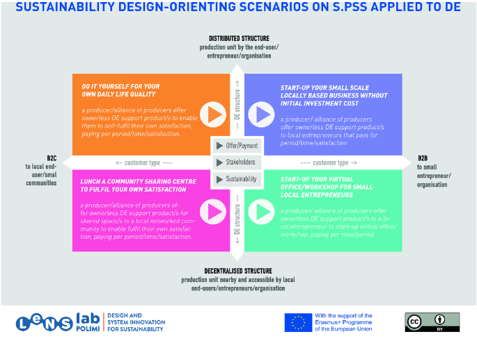
SDOS on S.PSS and DE tool

3.1 Sustainability Design-Orienting Scenarios (SDOS) on S.PSS and DE
Aims
The objective of Sustainability Design-Orienting Scenarios (SDOS) on S.PSS and DE (Fig. 1) is to orient the design process towards sustainable system solutions by using immersive and inspiring scenario videos to stimulate the generation of S.PSS-based DE ideas for all.
Components
The Sustainability Design-Orienting Scenarios on S.PSS and DE consist of:
-
Four main visions’ videos
-
Three sub-videos presenting options for all the visions in terms of:
-
Offer/payment
-
System configuration
-
Sustainability.
-
Integration into the MSDS design process
The SDOS on S.PSS and DE is used in Ideas generation oriented to sustainability to stimulate the generation of ideas (Fig. 2).

Integrating SDOS Scenario on S.PSS and DE into the MSDS process
How to use the SDOS on S.PSS and DE
The tool is used in two simple steps:
First, open the SDOS on S.PSS and DE tool. Play the four videos of the four visions, to get initial design inputs through sample stories (Fig. 3).

The menu page of the SDOS on S.PSS and DE tool with the links to the four vision videos
Secondly, play the three sub-videos, to open up sample stories linked to all options related to:
-
Offer/payment
-
System configuration
-
Sustainability (Fig. 4)
Fig. 4 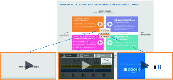
SDOS on S.PSS and DE tool links to the three sub-videos visualizing offer/payment, system configuration and sustainability

Availability and requested resources
The SDOS on S.PSS and DE tool is an open-access tool that can be downloaded for free from www.lens-international.org, ‘Tools’ section. A computer, a PDF reader and Internet connection are required to access the tool.
The tool may be used by a single designer, though the support of a multi-disciplinary team is preferable.
This tool requires 15 min to explore and get inspired by the proposed visions.
3.2 Innovation Diagram for S.PSS and DE
Aims
The objective of the Innovation Diagram for S.PSS and DE (Fig. 5) is to help designers to position and characterize existing offers and competitors and select promising ideas for new concept profiling.

Innovation Diagram for S.PSS and DE
Components
The diagram consists of:
-
Polarity diagram concept profile
-
Digital sticky notes
-
Database of labels.
Integration into the MSDS design process
The Innovation Diagram for S.PSS and DE is used at various stages of the design process (Fig. 6).

Integrating Innovation Diagram for S.PSS and DE integrated into MSDS design process
-
In Analysis of the project promoters and the reference context, it can be used to:
-
Analyse the current offer and the related competitors’ offers to orientate promising ideas.
-
-
In Visions, clusters and ideas selection and System concept development it can be used to:
-
Select, map and cluster the most promising ideas and create the profile and S.PSS and DE concept.
-
How to use the Innovation Diagram for S.PSS and DE
First, open the tool and move to the “…_existing offer” slide. Work in the “existing offer” slide to position an existing offer (Fig. 7). Select the company/organization icon (1) and choose one of the DE types to substitute the general one. Paste the label in the diagram and write the company/organization name in the free space on the label.

The existing offer slide of the Innovation Diagram for S.PSS and DE
The second step is to characterize the existing offer by specifying all of the following (Fig. 8):

Elements to characterize in the existing offer
-
Provider (1). Select the company/organization structure label, and choose one of the Offer type characterization icons (Distributed, Decentralized or Centralized and its sector, i.e. energy Generation, Food production, Water management, Manufacturing, Software development or Knowledge) to substitute the general one. Place in the provided section and write the company/organization name in the free space on the label.
-
Customer (2). Select customer/s (B2B–B2C) structure label icon/s and choose one of the characterization icons to substitute the general one. Place in the customer section and write customer/s name in the free space on the label.
-
Type of PSS (3). Select the S.PSS type of the offer (if any): PRODUCT-ORIENTED, USE-ORIENTED, RESULT-ORIENTED and place it in the S.PSS type section. Remember, that in most cases existing offers are not S.PSS.
-
Offered Products & owners (4). Select the product icon representing what the company offers and paste in the products section. Select who retains the product OWNERSHIP (provider or customer) and place the label in the provider/customer label.
-
Offered Services & providers (5). Select the service icon representing what the company offers and paste in the service section. Select who PROVIDES the service and place the label in the provider label.
-
What is paid (6). Select the icon describing what is paid by the customer/s and place the label in the payment section.
-
Offer configuration (7). Select the DE type icon of the offer and paste it in the DE type space. Select its structure icon and place it in the nearby space.
The same process to characterize the existing offer could be done in relation to competitors, by moving to the “…_Competitors” slide. Finally, the Innovation Diagram could be used to insert and position promising ideas designed with the idea boards (SDO toolkit), within the “…_Concept” slide (Fig. 9).

The concept slide of the Innovation Diagram for S.PSS and DE with the SDO idea boards
Now it is time to generate new ideas spotting the areas that are left empty (Fig. 10). Identify and cluster those ideas that can be combined to draft the system concept. Write a text (max 200 characters) outlining the preliminary system concept.

The concept slide of the Innovation Diagram: new idea generation, idea clustering and system concept drafting
Finally, profile an S.PSS and DE draft concept by copying and pasting characterizing icons of the emerging S.PSS and DE concept (Fig. 11).

Innovation Diagram: profiling an S.PSS and DE draft concept
Availability and requested resources
The Innovation Diagram for S.PSS and DE is an open access tool that can be downloaded for free from www.lens-international.org, ‘Tools’ section. A computer and a PowerPoint reader are needed to access the tool. This tool requires at least:
-
20 min to position and characterize the existing offer, 15 min to position and characterize the competitors,
-
45 min to select promising ideas, generate new ones, cluster them and identify/describe/profile a draft concept.
3.3 Concept Description Form for S.PSS and DE
Aims
The objective of the Concepts Description Form for S.PSS and DE (Fig. 12) is to finalize the description and characterization of a new S.PSS and DE concept.

Concept Description Form for S.PSS and DE
Components
It consists of a sum-up of the concept with:
-
Concept title
-
Satisfaction unit
-
Concept description
-
Concept profiling, i.e. Provider, Customer, Type of S.PSS, offered Products & owner, Offered services & provider, What is paid, Offer configuration.
Integrating the tool into the MSDS design process
The Concept Description Form for S.PSS and DE is used in System Concept Design to describe and profile the designed S.PSS and DE concept (Fig. 13).

Concept Description Form for S.PSS and DE integrated into the MSDS design process
How to use the S.PSS and DE concept description form
The Concept Description Form can be used in three simple steps (Fig. 12). First, write the title and the description of the S.PSS and DE concept. Secondly, indicate the UNIT OF SATISFACTION of the concept. Finally, characterize the concept with the information in all the fields.
Availability and requested resources
Like the previously described tools, the Concept Description Form for S.PSS and DE is an open access tool that can be downloaded for free from www.lens-international.org, ‘Tools’ section. A computer, a PowerPoint reader, and Internet connection are required to access this tool. The tool may be used by a single designer, though the support of a multi-disciplinary team is preferable. This tool requires at least 15 min to complete.
3.4 System Map for S.PSS and DE
Aims
The purpose of the System Map for S.PSS and DE (Fig. 14) is to support (co-)designing, visualization and configuration of the system structure, indicating the actors involved and their interactions in distributed systems providing additional support to its users defining DE configuration.Footnote 10

System Map for S.PSS and DE
Components
The System Map for S.PSS and DE contains graphical representations of:
-
Stakeholders involved;
-
Flows/interactions: physical, financial, informational and labour performance;
-
System configurator: Distributed, Decentralized, Centralized.
Integration into the MSDS design process
The System Map for S.PSS and DE is used at various stages of the design process (Fig. 15).

System Map for S.PSS and DE integration into the MSDS design process
-
In Product-Service System Concept Design it can be used to:
-
Visualize stakeholders’ interaction within the concept
-
-
In Product-Service System detailed design it can be used to:
-
Further detail and visualize stakeholders’ interactions within the concept.
-
How to use the System Map for S.PSS and DE
The System Map for S.PSS and DE enables comprehensive visualization of the system structure (Fig. 16). To start with, identify boundaries, including offer boundary and system boundary.

System Map for S.PSS and DE: design offer boundary and system boundary
Later, identify the actors involved: select a structure icon, then choose a characterization icon to substitute the general one, and finally drag and drop into the system map (Fig. 17).

System Map for S.PSS and DE: design and position actors
Now it is time to define interaction flows using arrows and descriptions. Interaction flows can be material flow, information flow, financial flow and labour flow (see the Legend in Fig. 18). Remember that the reading order is essential, thus note the numbering of interaction flows.

System Map for S.PSS and DE: design interaction flows
Finally, use dashed squares to indicate ownership (owner and product inside) and squares around actors to indicate partnership (Fig. 19).

System Map for S.PSS and DE: design ownership and partnership
Availability and requested resources
The System Map for S.PSS and DE can be drawn on paper with no need for software. It is, however, advisable to use slideshow software, in order to facilitate management and modifications. The System Map for S.PSS and DE with labels and icon repositories is open access, available for free download at www.lens-international.org, “Tools” section. The tool is based on a layout and a set of standardized icons, usable with PowerPoint readers. From this base it is possible to modify the various icons and add new ones.
The tool was developed for use by any design team member, and no particular graphic skills are required. The time required to set up a System Map for S.PSS and DE depends on the level of details along the design process; nevertheless, it could range from approximately 60–90 min.
3.5 S.PSS and DE Idea Boards (embedded into the SDO toolkit)
Aims
The objective of S.PSS and DE Idea Boards (embedded into the SDO toolkit) (Fig. 20) is to support designers in orientating the system idea generation design process towards sustainable DE for all S.PSS-based solutions.

S.PSS and DE Idea Boards (SDO toolkit)
Components
The tool consists of 6 Idea Boards, one per criteria as listed below, and a corresponding set of guidelines suggesting S.PSS-based DE ideas through innovative stakeholder interactions:
-
Complement the DE hardware offer with Life Cycle services
-
Offer ownerless DE systems as enabling platform
-
Offer ownerless DE systems with full services
-
Optimize stakeholders’ configuration
-
Delink payment from hardware/resource purchases
-
Optimize DE systems structure.
Integration into the MSDS design process
The S.PSS and DE Idea Boards (SDO) are used in idea generation oriented to sustainability to orientate the system idea generation design process towards sustainable S.PSS-based solutions for all (Fig. 21).

S.PSS and DE Idea Boards (SDO) integration into the MSDS design process
How to use S.PSS and DE Idea Boards (SDO)
The following steps must be performed to access the tool:
-
Download the SDO toolkit from www.lens-international.org
-
Type project name, etc.
-
Click on S.PSS and DE sustainability dimension
-
Click on orientate concept.
To orientate the system idea using the S.PSS and DE Idea Boards (Fig. 22), select the idea tables one by one (one for each criterion) (1). Then, read the guidelines (a set for each criterion) (2) and check the guideline’s example for further inspiration (3). Drag and drop the “digital post-it” and describe the emerged system ideas (for each criterion) (4). You can see and read more information on the case related to the specific guideline (5).

S.PSS Idea Boards (embedded into SDO toolkit)
Availability and requested resources
S.PSS and DE Idea Boards are embedded into the SDO toolkit. The tool is also available for free download at www.lens-international.org, “Tool” page. A computer, a PowerPoint reader and Internet connection are needed to use the tool. Idea Boards require at least 75 min to complete.
3.6 Strategic Analysis Toolkit (SAT) for DE for Socio-Economic Ecosystems (SEE)
The Strategic Analysis Toolkit, SAT, consists of tools which first identify the actors and their activities in the ecosystem; then the infrastructure and needs of the actors; clarifies the goal, problem statement definition, design brief and unit of satisfaction using participatory design tools; and, finally a tool for competitor analysis. This section introduces tools related to processes and sub-processes within the Strategic analysis stage in the MSDS methodology (Fig. 23).

Strategic analysis toolkit (SAT) integration into the MSDS design process
Aims
The strategic analysis toolkit aims to help a designer in Sustainable Product-Service System Design with an intervention focus on Socio-Economic Ecosystems (SEE) of multi-cultural and diverse communities engaged in distributed economic activities.
Process 1: Project Socio-Economic Ecosystem Analysis
-
1.
Awesome Actors Tool. The first step of strategic analysis is to identify all the actors and their aspects of activity, best accomplished by interviewing local administrators and visionaries (e.g. local elders, thought leaders, NGOs, etc.). The Awesome Actors Tool helps its users to identify the main value proposition of the local ecosystem, its problems, all actors and their activities (Table 2).
Table 2 Awesome actors tool -
2.
KFPS Knowledge Mining Tool. This tool helps to identify existing infrastructure and required transformations. Interviewing local administrators/visionaries helps in acquiring information on service, product-service, and infrastructure transformations planned and required in the local ecosystem (Table 3).
Table 3 KFPS knowledge mining tool -
3.
Empathy Mapping, AEIOU Mapping, Value Opportunity Analysis, SWOT, PESTLE, System Map. A set of tools supports their users in meeting the actual actors and understanding their needs, e.g. Value Opportunity Analysis tool (Table 4).
Table 4 Value opportunity analysis
Process 2: Defining intervention context
-
4.
Co-design using “Clarify Your Goal”. The tool adopted from Frog Design [2] helps to define design goals, identify the problem statement, design brief and unit of satisfaction (Fig. 24).
Fig. 24 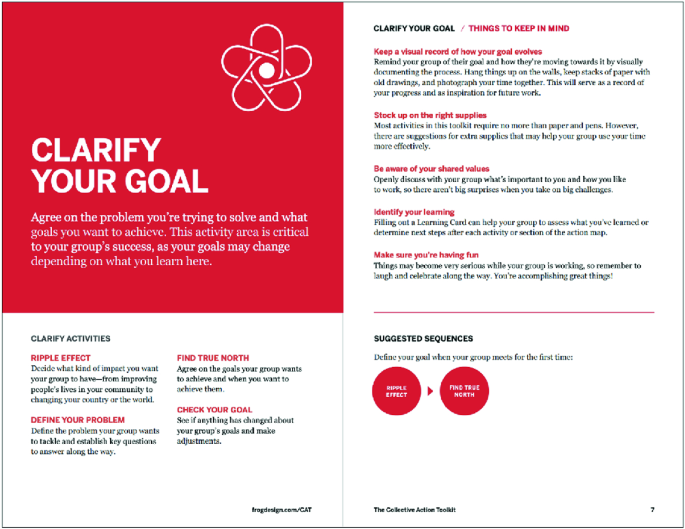
“Clarify Your Goal” section of Frog Collective Action Toolkit
-
5.
Competitor analysis on form, category, generic, budget level (using Porter's five forces analysis if applicable [5]). The tool helps to collect the competition space knowledge (Table 5). Competitors of the system are found based on the clarified goal of the design intervention and the main value proposition of the local context.
Table 5 Competitor analysis on form, category, generic and budget levels

Currently, the toolkit has been designed and tested on two SEE contexts, both located in Assam, India.
Availability and resources required
Downloadable files of each tool can be found in Banerjee et al. [1] with the following information on resources and time needed to carry out design processes using each tool.
3.7 Distributed Manufacturing (DM) Applied to PSS Design Toolkit
The DM applied to PSS design toolkit (Fig. 25) has been tested with students, experts, manufacturing industry professionals and design practitioners through three rounds of empirical application, to ensure its effectiveness and usability [4].

The DM applied to PSS design toolkit
Aims
The DM applied to PSS design toolkit serves two purposes: (1) it provides its users with knowledge about potential DM opportunities and (2) supports idea generation for PSS solutions improved with DM features.
Components
The toolkit consists of four elements, each of which is described below in detail:
-
40 near-future scenario cards
-
3 scenario cards’ selection diagrams
-
1 introductory card
-
1 idea generation diagram.
Near-future scenario cards
Double-sided near-future scenario cards are brief snapshots illustrating how specific features of Distributed Manufacturing can be applied to Product-Service Systems throughout their life cycle (Fig. 26). Scenario cards are made to inspire and to encourage future-oriented thinking. Furthermore, they serve an educational purpose and contain a sufficient amount of information to support a learning process about DM and PSS.

Front and back sides of the near-future scenario card
Scenario cards’ selection diagrams
Scenario cards’ selection diagrams on which scenario cards are mapped illustrate areas tackled by the near-future scenarios. The toolkit contains three scenario cards’ selection diagrams (Fig. 27): [1] the stage-by-stage DM and PSS connection diagram (1); [2] the DM features diagram (2); and [3] the PSS implementation barriers diagram (3). These diagrams are made to facilitate relevant scenario cards’ selection. Each diagram classifies scenario cards according to PSS life cycle stages and/or DM features, or PSS implementation barriers and contains questions helping to select relevant cards.

Scenario cards’ selection diagrams
Introductory card
This toolkit is made to facilitate new PSS development as well as to improve existing PSS solutions. The introductory card allows the toolkit’s users to decide whether they would like to create a new PSS or to improve an existing one (Fig. 28). Depending on their choice, one of the three scenario cards’ selection diagrams must be selected.

The introductory card
Idea Generation Diagram
The Idea generation diagram (Fig. 29) is used for positioning ideas developed using near-future scenario cards.

Idea generation diagram
Integration into the MSDS design process
The DM applied to PSS design toolkit can be best used to facilitate idea generation for S.PSS solutions enabled by DM. In addition, near-future scenario cards can be used to explore and analyse existing examples of DM and learn about the DM potential. Finally, the idea generation diagram can be used to position, cluster and select promising developed ideas for further detailing (Fig. 30).

DM applied to PSS design toolkit’s integration into the MSDS design process
How to use the DM applied to PSS design toolkit
Each element of the DM applied to PSS design toolkit is created to be used in a purposeful order (Fig. 31): first, the identification of the goal using the introductory card (1); second, the selection of relevant scenario cards using the scenario cards’ selection diagrams (2); third, DM applied to PSS idea generation using near-future scenario cards (3); and, finally, positioning of developed ideas on the idea generation diagram (4).

A proposed design process of the DM applied to PSS design toolkit
Availability and resources required
The DM applied to PSS design toolkit is available for free download (from www.lens-international.org, “Tools” section). The toolkit needs to be printed; other required resources are post-it notes and pens.
The toolkit may be used by a team of designers, design students, or multidisciplinary team. It is advisable to involve various system actors. The toolkit requires at least 120 min to conduct a complete ideation process.
3.8 Summary
This chapter has presented several tools supporting the design of S.PSS applied to DE that have been developed or updated during the LeNSin project. Many other tools have been developed to support system design for sustainability for all and a wide selection of those can be found and downloaded from the LeNS platform (www.lens-international.org).
Notes
- 1.
Design for Sustainability (D4S): A Step-By-Step Approach (UNEP funded, 2005–2009) (see [6]).
- 2.
SusHouse: Strategies towards the Sustainable Household (EU funded, 1998–2000) (see [9]).
- 3.
ProSecCo: Product-Service Co-design (EU funded, 2002–2004).
- 4.
HiCS: Highly Customerised Solutions (EU funded, 2001–2004) (see Manzini et al. [3]).
- 5.
MEPSS: MEthodology for Product Service System development (EU funded, 2002–2005) (see [8]).
- 6.
SusProNet: Sustainable Product-Service co-design Network (EU funded, 2002–2005) (see [7]).
- 7.
LeNS: Learning Network on Sustainability (2008–2010).
- 8.
LeNSes: Focused on System Design for Sustainable Energy for all (EU-funded, Oct 2013–Oct 2016).
- 9.
This is the one of the outcomes of the LeNSin project, creating, integrating and updating tools produced by the project partners together with other existing tools and approaches linked to system design for sustainability. The tools described here are a selection of those that have been used and tested during a set of pilot courses as part of the LeNSin project and in several studies with companies and industry experts.
- 10.
The original System Map tool is presented in detail in the first LeNS book, Sect. 3.6 [10].
References
Banerjee S, Upadhyay P, Punekar RM (2019) Contextualising sustainable product-service design methods for distributed economies of India. In: Ambrosio M, Vezzoli C (eds) Designing sustainability for all: Proceedings of the 3rd LeNS world distributed conference, vol 1, pp 270–275
Frog Design (2016) Collective action toolkit. https://www.frogdesign.com/wp-content/uploads/2016/03/CAT_2.0_English.pdf
Manzini E, Collina L, Evans S (eds) (2004) Solution-oriented partnership. Cranfield University, Cranfield
Petrulaityte A, Ceschin F, Pei E, Harrison D (2020) Applying distributed manufacturing to product-service system design: a set of near-future scenarios and a design tool. Sustainability 12(12):4918
Porter ME, Kramer MR (2006) Strategy and society: the link between competitive advantage and corporate social responsibility. Harvard Bus Rev
Tischner U, Vezzoli C (2009) Product-service systems: tools and cases. In: Crul M, Diehl JC (eds) Design for sustainability (D4S): a step-by-step approach (United Nations Environment Programme UNEP)
Tukker A, Tischner U (eds) (2006) New business for old Europe: product services, sustainability and competitiveness. Greenleaf Publishing, Sheffield, UK
van Halen C, Vezzoli C, Wimmer R (eds) (2005) Methodology for product service system. How to develop clean, clever and competitive strategies in companies. Van Gorcum, Assen, Netherlands
Vergragt PJ (2002) Strategies towards the sustainable household. Final report. TBM, Delft University of Technology, Delft
Vezzoli C, Kohtala C, Srinivasan A, Diehl JC, Fusakul SM, Xin L, Sateesh D (2014) Product-service system design for sustainability. Greenleaf Publishing, Sheffield, UK
Author information
Authors and Affiliations
Corresponding author
Editor information
Editors and Affiliations
Rights and permissions
Open Access This chapter is licensed under the terms of the Creative Commons Attribution 4.0 International License (http://creativecommons.org/licenses/by/4.0/), which permits use, sharing, adaptation, distribution and reproduction in any medium or format, as long as you give appropriate credit to the original author(s) and the source, provide a link to the Creative Commons license and indicate if changes were made.
The images or other third party material in this chapter are included in the chapter's Creative Commons license, unless indicated otherwise in a credit line to the material. If material is not included in the chapter's Creative Commons license and your intended use is not permitted by statutory regulation or exceeds the permitted use, you will need to obtain permission directly from the copyright holder.
Copyright information
© 2021 The Author(s)
About this chapter

Cite this chapter
Vezzoli, C., Petrulaityte, A., Banerjee, S., Upadhyay, P., Punekar, R.M. (2021). Designing S.PSS and DE: New Horizons for Design. In: Vezzoli, C., Garcia Parra, B., Kohtala, C. (eds) Designing Sustainability for All. Lecture Notes in Mechanical Engineering. Springer, Cham. https://doi.org/10.1007/978-3-030-66300-1_4
Download citation
DOI: https://doi.org/10.1007/978-3-030-66300-1_4
Published:
Publisher Name: Springer, Cham
Print ISBN: 978-3-030-66299-8
Online ISBN: 978-3-030-66300-1
eBook Packages: EngineeringEngineering (R0)