
Abstract
In previous chapters we discussed several semiconductor devices including the diode, the BJT, the FET, the operational amplifier and the current feedback amplifier. There are several other devices that are available to the designer and we will discuss some of these in this chapter. At the end of the chapter the student will be able to
Access this chapter
Tax calculation will be finalised at checkout
Purchases are for personal use only
Bibliography
J. Graeme, Photodiode Amplifiers: Op Amp Solutions (McGraw-Hill, New York, 1996)
Author information
Authors and Affiliations
Problems
Problems
-
1.
Design a system using a photocell and an op-amp as a comparator to switch on a motor when ambient light exceeds a certain level.
-
2.
Design a system using a photocell and a transistor to switch on an alarm when ambient light rises above a specified level. Indicate the changes needed for the system to indicate the absence rather than the presence of light.
-
3.
Design a light metre to cover the ranges 10–10,000 lx using the photo diode in the zero bias mode shown in Fig. 14.92 and a 1 mA milliameter.
Fig. 14.92 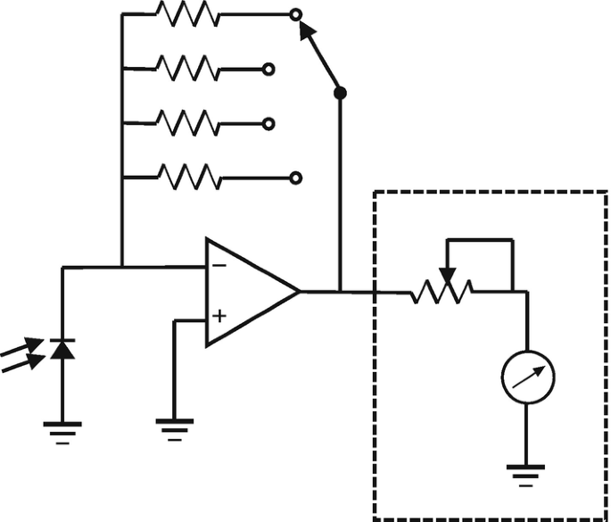
Circuit for question 3
-
4.
Explain the operation of the phototransistor and indicate one method by which the light-induced current can be converted to a useable output voltage.
-
5.
Using the photoresistor opto-isolator along with an op-amp, design a remote gain control amplifier system.
-
6.
Outline the approach by which the photofet opto-coupler can be used in the design of (i) a voltage-controlled Sallen-Key low-pass filter and (ii) a voltage-controlled Wien bridge oscillator.
-
7.
A microcontroller with a 0–5 V output is used to activate another digital system from which it must be isolated. Use the configuration shown in Fig. 14.93 to realize such a system with VCC1 = VCC2 = 5 V.
Fig. 14.93 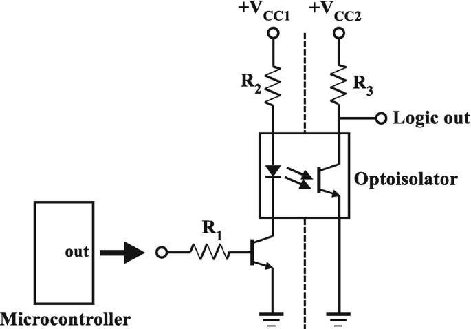
Circuit for question 7
-
8.
A thyristor used in a static power switch has IG = 750 μA, VGC = 0.7 V, VAC = 0.4 V and IH = 15 mA. Using VTRIG = 4 V and VCC = 36 V, determine the resistor RG in order to trigger the thyristor into conduction and the resulting anode current for a load RL = 700 Ω in the circuit of Fig. 14.37.
-
9.
For an operating frequency of 300 Hz, find the capacitor value required to achieve a phase lag of 75o with a resistor of 56 k.
-
10.
Describe the operation of a static triac switch for controlling AC power to a load. Show how phase control can be introduced to allow control over the full half cycle.
-
11.
Design a system to remotely switch on a large (8 A) heating load using the phototriac and a triac.
-
12.
Using a Shockley diode having VS = 15 V, VH = 1.3 V and IH = 5 mA, design a relaxation oscillator to produce a linear waveform with a slope of 100 mV/μs.
-
13.
Explain how a diac can be used to improve the turn-on performance of a triac-controlled power switch.
-
14.
A UJT with η = 0.65 is powered by a 12 V supply. If the emitter is at zero potential, determine the reverse bias across the pn junction.
-
15.
Using the 2N2926 unijunction transistor, design a relaxation oscillator with a frequency of oscillation of 12 kHz and operating from a 15 V supply. Provide a buffered voltage output from the system. For this UJT, η = 0.56 → 0.75, IP(mx) = 5 μA and IV(mx) = 4 mA.
-
16.
Determine the oscillating frequency of the relaxation oscillator shown in Fig. 14.94 where the UJT has η = 0.63.
Fig. 14.94 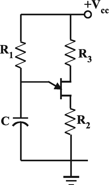
Circuit for question 16
-
17.
Explain how the PUT differs from the UJT.
-
18.
Using the 2N6027 PUT, design a relaxation oscillator with a frequency of oscillation of 5 kHz and operating from a 24 V supply. For the 2N6027, RG = R1//R2 = 10 k, and typical current values are IP = 4 μA and IV = 150 μA.


Rights and permissions
Copyright information
© 2021 Springer Nature Switzerland AG
About this chapter

Cite this chapter
Gift, S.J.G., Maundy, B. (2021). Special Devices. In: Electronic Circuit Design and Application. Springer, Cham. https://doi.org/10.1007/978-3-030-46989-4_14
Download citation
DOI: https://doi.org/10.1007/978-3-030-46989-4_14
Published:
Publisher Name: Springer, Cham
Print ISBN: 978-3-030-46988-7
Online ISBN: 978-3-030-46989-4
eBook Packages: EngineeringEngineering (R0)