
Abstract
A filter is an electrical network that passes signals within a specified band of frequencies while attenuating those signals that fall outside of this band. Passive filters utilize passive components, namely, resistors, capacitors and inductors, while active filters contain passive as well as active components such as transistors and operational amplifiers. Passive filters have the advantage of not requiring an external power supply as do active filters. However, they often utilize inductors which tend to be bulky and costly, whereas active filters utilize mainly resistors and capacitors. Additionally, active filters can produce signal gain and have high input and low output impedances which allow simple cascading of systems with little or no interaction between stages. This chapter discusses the principles of active filter operation and treats with several types and configurations of active filters. At the end of the chapter, the student will be able to:
This is a preview of subscription content, log in via an institution.
Buying options
Tax calculation will be finalised at checkout
Purchases are for personal use only
Learn about institutional subscriptionsBibliography
R. Schaumann, M. Van Valkenburg, Design of Analog Filters, 1st edn. (Oxford University Press, 2001)
T. Kugelstadt, in Active filter design techniques in op amps for everyone, ed. by R. Mancini, (Texas Instruments, 2002)
A. Waters, Active filter design (Mc Graw Hill, 1991)
Author information
Authors and Affiliations
Problems
Problems
-
1.
Design a first-order low-pass non-inverting filter with unity gain and a break frequency of 5 kHz.
-
2.
Design a first-order non-inverting low-pass filter with gain of 8 and a cut-off frequency of 17 kHz.
-
3.
Design a first-order low-pass filter with gain of 12 and a cut-off frequency of 25 kHz using the inverting configuration.
-
4.
Show that in a first-order low-pass filter, the amplitude response is down 3 dB at the cut-off frequency and determine the phase angle of the output relative to the input at that frequency.
-
5.
Using the Sallen-Key configuration, design a second-order low-pass Butterworth filter with unity gain and a cut-off frequency of 50 kHz. Ensure that offset voltage is minimized.
-
6.
Show that in the Sallen-Key second-order low-pass Butterworth filter, for the case where the network resistors are equal and the network capacitors are equal, the gain must be 1.6. Hence repeat the design of Question 5 using this modified approach.
-
7.
Show that in the Sallen-Key second-order unity-gain low-pass filter configuration shown in Fig. 11.61, if R1 = R2 and C2 = 2C1, then the transfer function reduces to a second-order Butterworth response
Fig. 11.61 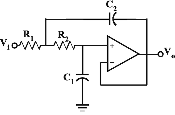
Circuit for Question 7
.

-
8.
Design a VCVS second-order unity-gain low-pass Chebyshev filter with a cut-off frequency of 22 kHz and a ripple width RWdB = 1dB.
-
9.
Design a VCVS second-order unity-gain low-pass Bessel filter with a cut-off frequency of 550Hz.
-
10.
Design a MFB second-order low-pass Butterworth filter with a gain of 8 and a cut-off frequency of 3 kHz.
-
11.
Design a VCVS third-order unity-gain low-pass Butterworth filter with a cut-off frequency of 33 kHz. What is the ultimate roll-off rate of such a filter?
-
12.
Show that in the Sallen-Key third-order unity-gain low-pass filter configuration shown in Fig. 11.62, if R1 = R2 = R3 and C2 = 2C3 and C1 = C3/2, then the transfer function reduces to a third-order Butterworth response. Hence repeat Question 11 using this simplified design procedure
Fig. 11.62 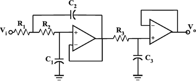
Circuit for Question 12
.

-
13.
Design a VCVS fourth-order unity-gain low-pass Chebyshev filter with a cut-off frequency of 12 kHz and 3 dB ripple width.
-
14.
Design a VCVS fifth-order unity-gain low-pass Butterworth filter with a cut-off frequency of 1200 Hz.
-
15.
Design a first-order high-pass non-inverting filter with unity gain and a break frequency of 5 kHz.
-
16.
Design a first-order non-inverting high-pass filter with gain of 8 and a cut-off frequency of 17 kHz.
-
17.
Design a first-order high-pass filter with gain of 15 and a cut-off frequency of 10 kHz using the inverting configuration.
-
18.
Show that in a first-order high-pass filter, the amplitude response is down 3 dB at the cut-off frequency and determine the phase angle of the output relative to the input at that frequency.
-
19.
Using the Sallen-Key configuration, design a second-order high-pass Butterworth filter with unity gain and a cut-off frequency of 5 kHz.
-
20.
Show that in the Sallen-Key second-order high-pass Butterworth filter, for the case where the network resistors are equal and the network capacitors are equal, the gain must be 1.6. Hence repeat the design of Question 19 using this modified approach.
-
21.
Show that in the Sallen-Key second-order unity-gain high-pass filter configuration shown in Fig. 11.63, if R1 = 2R2 and C1 = C2, then the transfer function reduces to a second-order high-pass Butterworth response
Fig. 11.63 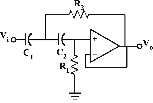
Circuit for Question 21
.

-
22.
Design a VCVS second-order unity-gain high-pass Chebyshev filter with a cut-off frequency of 14 kHz and a ripple width RWdB = 1dB.
-
23.
Design a VCVS second-order unity-gain high-pass Bessel filter with a cut-off frequency of 5 kHz.
-
24.
Design a MFB second-order high-pass Butterworth filter with a gain of 6 and a cut-off frequency of 2 kHz.
-
25.
Design a VCVS third-order unity-gain high-pass Butterworth filter with a cut-off frequency of 900 Hz. What is the ultimate roll-off rate of such a filter?
-
26.
Show that in the Sallen-Key third-order unity-gain low-pass filter configuration shown in Fig. 11.64, if C1 = C2 = C3 and R1 = 2R3 and R2 = R3/2, then the transfer function reduces to a third-order Butterworth response. Hence repeat Question 25 using this simplified design procedure
Fig. 11.64 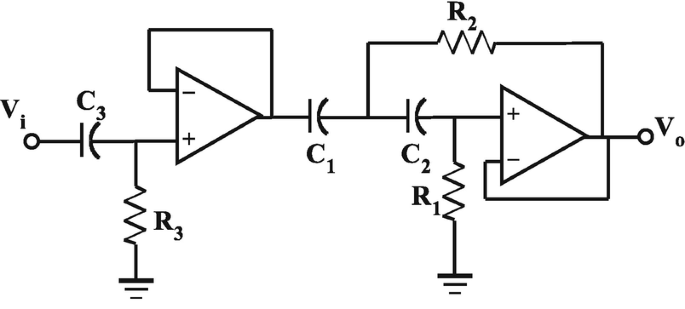
Circuit for Question 26
.

-
27.
Design a VCVS fourth-order unity-gain high-pass Chebyshev filter with a cut-off frequency of 1200 Hz and 2 dB ripple width.
-
28.
Design a VCVS fifth-order unity-gain high-pass Bessel filter with a cut-off frequency of 6 kHz.
-
29.
Using the VCVS band-pass filter shown in Fig. 11.65, design a Sallen-Key second-order band-pass filter having C1 = C2, R1 = R2 with a centre frequency of 13 kHz and a quality factor of 8
Fig. 11.65 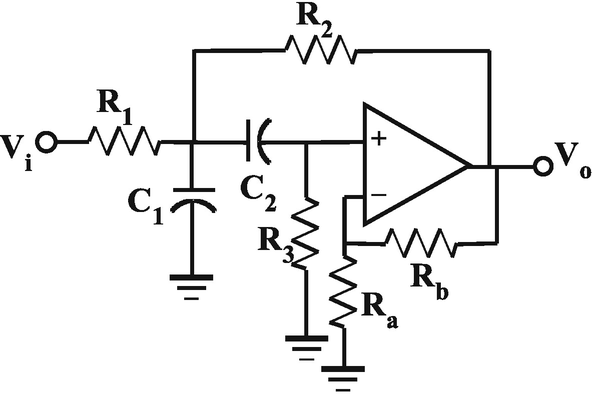
Circuit for Question 29
.

-
30.
For the VCVS band-pass filter shown in Fig. 11.65, develop design equations for R1, R2 and R3 if C1 = C2 = C and 1 + Rb/Ra = 2. Hence, design a VCVS band-pass filter having fo = 20 kHz, Q = 6 and G = 10.
-
31.
Design a second-order MFB band-pass filter with f0 = 2 kHz, Q = 9 and G = 5. Use the circuit shown in Fig. 11.66
Fig. 11.66 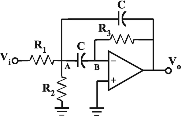
MFB band-pass filter for Question 31
.

-
32.
For the second-order MFB band-pass filter shown in Fig. 11.66, develop design equations without imposing the condition C1 = C2. Hence, design a second-order MFB band-pass filter having fo = 1 kHz, Q = 5 and G = 10.
-
33.
Design a second-order Wien band-pass filter with f0 = 60 Hz, Q = 10 and G = 2.
-
34.
Design a twin-T notch filter having a notch frequency of 2.5 kHz and Q = 25.
-
35.
Using the circuit shown in Fig. 11.67, design a Wien notch filter to have a notch frequency of 200 Hz, a Q of 25 and a gain of 2
Fig. 11.67 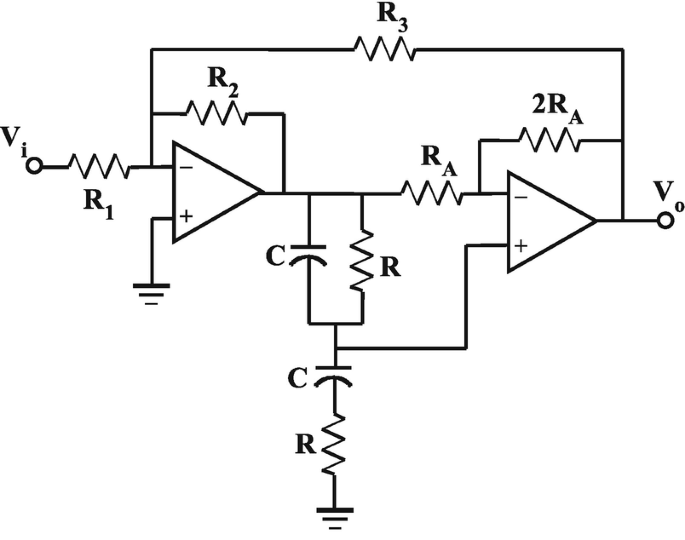
Circuit for Question 35
.

-
36.
By using a ganged potentiometer for R and two banks of switched capacitors for C, convert the Wien notch filter in Fig. 11.67 to a variable frequency circuit and specify the frequency range.
-
37.
Develop the transfer function for a Tow-Thomas biquadratic filter.
Rights and permissions
Copyright information
© 2021 Springer Nature Switzerland AG
About this chapter

Cite this chapter
Gift, S.J.G., Maundy, B. (2021). Active Filters. In: Electronic Circuit Design and Application. Springer, Cham. https://doi.org/10.1007/978-3-030-46989-4_11
Download citation
DOI: https://doi.org/10.1007/978-3-030-46989-4_11
Published:
Publisher Name: Springer, Cham
Print ISBN: 978-3-030-46988-7
Online ISBN: 978-3-030-46989-4
eBook Packages: EngineeringEngineering (R0)