
Abstract
The in-situ characterization approach can be utilized to develop insights into the mechanics of a wide diversity of materials. This chapter introduces the application of in-situ mechanical investigations for different materials science problems. The applicability of in-situ measurement techniques over a wide range of length scales (from atomic- to macroscale) and load scales (nano- to Mega-Newton) makes them highly suited for developing a comprehensive understanding of deformation phenomena activated in materials. Testing in high-resolution microscopes is beneficial to manipulate and examine the mechanical response of extremely fine nanomaterials. Real-time imaging of deformation is advantageous to establish morphology-mechanics correlation for different nanomaterials, such as 0D nanoparticles, 1D nanotubes or nanowires, and 2D nanosheets or nanoribbons. Superior mechanical properties of nanomaterials are harnessed by using them as reinforcement fillers in metal, ceramic, or polymer matrices. The in-situ mechanics approach is useful to decipher the interface mechanics and strengthening mechanisms. The real-time imaging approach can provide insights into load-transfer and failure mechanisms in specialized 3D architectures and metamaterials. The effect of tweaking geometrical parameters, such as unit cell shape, size, and angles of inclination on deformation characteristics can be determined with real-time imaging. Since the individual features in metamaterials can have nano- and microscale dimensions, high-resolution imaging provides insights into the local response which affects the bulk, overall response. Coupling mechanical measurements with the thermal stimulus or electrical output during in-situ testing is an advantageous strategy to probe the mechanics and transformations in smart materials, such as shape memory or piezoelectric materials. The in-situ approach is useful for examining biological materials. Real-time imaging can provide insights into mechanisms activated in different regions and along different orientations of the tissues. The application of the in-situ technique for probing the deformation of irradiated materials is discussed toward the end of the chapter. Table 5.1 below summarizes the application of in-situ mechanics approach for different classes of materials, mechanistic understanding obtained by multi-scale imaging, and quantitative mechanical properties. This table covers some of the key areas where the in-situ approach has gained popularity, but the applications of in-situ characterization are not limited to these categories and there are multiple avenues where the technique is utilized or has promising future potential. The subsequent sections discuss different materials science applications in greater detail. The challenges, solutions, advantages, and limitations are highlighted through different case studies. The readers are also referred to several supplementary videos throughout the chapter for better visualization and understanding of these applications.
Access this chapter
Tax calculation will be finalised at checkout
Purchases are for personal use only
References
Alducin D, Borja R, Ortega E et al (2016) In situ transmission electron microscopy mechanical deformation and fracture of a silver nanowire. Scr Mater 113:63–67. https://doi.org/10.1016/j.scriptamat.2015.10.011
Andersson RL, Ström V, Gedde UW et al (2014) Micromechanics of ultra-toughened electrospun PMMA/PEO fibres as revealed by in-situ tensile testing in an electron microscope. Sci Rep 4:6335. https://doi.org/10.1038/srep06335
Bhowmick S, Ozden S, Bizão RA et al (2018) High temperature quasistatic and dynamic mechanical behavior of interconnected 3D carbon nanotube structures. Carbon N Y 142:291–299. https://doi.org/10.1016/j.carbon.2018.09.075
Boesl B, Lahiri D, Behdad S, Agarwal A (2014) Direct observation of carbon nanotube induced strengthening in aluminum composite via in situ tensile tests. Carbon N Y 69:79–85. https://doi.org/10.1016/j.carbon.2013.11.061
Bustillos J, Zhang C, Boesl B, Agarwal A (2018) Three-dimensional graphene foam-polymer composite with superior deicing efficiency and strength. ACS Appl Mater Interfaces 10:5022–5029. https://doi.org/10.1021/acsami.7b18346
Cao C, Howe JY, Perovic D et al (2016) In situ TEM tensile testing of carbon-linked graphene oxide nanosheets using a MEMS device. Nanotechnology 27:28LT01
Casillas G, Palomares-Báez J, Rodríguez-López J et al (2012) In situ TEM study of mechanical behaviour of twinned nanoparticles. Philos Mag 92:4437–4453. https://doi.org/10.1080/14786435.2012.709951
Chen H, Gao Y, Zhang H et al (2004) Transmission-electron-microscopy study on fivefold twinned silver nanorods. J Phys Chem B 108:12038–12043. https://doi.org/10.1021/jp048023d
Chen Z, Ren W, Gao L et al (2011) Three-dimensional flexible and conductive interconnected graphene networks grown by chemical vapour deposition. Nat Mater 10:424–428. https://doi.org/10.1038/nmat3001
Chu K, Wang J, Liu Y, Geng Z (2018) Graphene defect engineering for optimizing the interface and mechanical properties of graphene/copper composites. Carbon N Y 140:112–123. https://doi.org/10.1016/j.carbon.2018.08.004
Deneen Nowak J, Mook WM, Minor AM et al (2007) Fracturing a nanoparticle. Philos Mag 87:29–37. https://doi.org/10.1080/14786430600876585
Ebenstein DM, Pruitt LA (2006) Nanoindentation of biological materials. Nano Today 1:26–33. https://doi.org/10.1016/S1748-0132(06)70077-9
Huang JY, Zheng H, Mao SX et al (2011) In situ nanomechanics of GaN nanowires. Nano Lett 11:1618–1622. https://doi.org/10.1021/nl200002x
Idowu A, Boesl B, Agarwal A (2018) 3D graphene foam-reinforced polymer composites – a review. Carbon N Y 135:52–71. https://doi.org/10.1016/j.carbon.2018.04.024
Issa I, Amodeo J, Réthoré J et al (2015) In situ investigation of MgO nanocube deformation at room temperature. Acta Mater 86:295–304. https://doi.org/10.1016/j.actamat.2014.12.001
Kiener D, Hosemann P, Maloy SA, Minor AM (2011) In situ nanocompression testing of irradiated copper. Nat Mater 10:608–613. https://doi.org/10.1038/nmat3055
Li S, Abdel-Wahab A, Demirci E, Silberschmidt VV (2014) Penetration of cutting tool into cortical bone: experimental and numerical investigation of anisotropic mechanical behaviour. J Biomech 47:1117–1126. https://doi.org/10.1016/j.jbiomech.2013.12.019
Li N, Wang H, Misra A, Wang J (2015) In situ nanoindentation study of plastic co-deformation in Al-TiN nanocomposites. Sci Rep 4:1–6. https://doi.org/10.1038/srep06633
Liao Z, Sandonas LM, Zhang T et al (2017) In-situ stretching patterned graphene nanoribbons in the transmission electron microscope. Sci Rep 7:211. https://doi.org/10.1038/s41598-017-00227-3
Liu D, Flewitt PEJ (2017) Deformation and fracture of carbonaceous materials using in situ micro-mechanical testing. Carbon N Y 114:261–274. https://doi.org/10.1016/j.carbon.2016.11.084
Liu F, Tang D-M, Gan H et al (2013) Individual boron nanowire has ultra-high specific young’s modulus and fracture strength as revealed by in situ transmission electron microscopy. ACS Nano 7:10112–10120. https://doi.org/10.1021/nn404316a
Liu Y, Karaman I, Wang H, Zhang X (2014) Two types of martensitic phase transformations in magnetic shape memory alloys by in-situ nanoindentation studies. Adv Mater 26:3893–3898. https://doi.org/10.1002/adma.201400217
Montemayor LC, Greer JR (2015) Mechanical response of hollow metallic nanolattices: combining structural and material size effects. J Appl Mech 82:071012. https://doi.org/10.1115/1.4030361
Nardecchia S, Carriazo D, Ferrer ML et al (2013) Three dimensional macroporous architectures and aerogels built of carbon nanotubes and/or graphene: synthesis and applications. Chem Soc Rev 42:794–830. https://doi.org/10.1039/c2cs35353a
Nieto A, Boesl B, Agarwal A (2015a) Multi-scale intrinsic deformation mechanisms of 3D graphene foam. Carbon N Y 85:299–308. https://doi.org/10.1016/j.carbon.2015.01.003
Nieto A, Dua R, Zhang C et al (2015b) Three dimensional graphene foam/polymer hybrid as a high strength biocompatible scaffold. Adv Funct Mater 25:3916–3924. https://doi.org/10.1002/adfm.201500876
Schwiedrzik J, Raghavan R, Bürki A et al (2014) In situ micropillar compression reveals superior strength and ductility but an absence of damage in lamellar bone. Nat Mater 13:740–747. https://doi.org/10.1038/nmat3959
Shan ZW, Adesso G, Cabot A et al (2008) Ultrahigh stress and strain in hierarchically structured hollow nanoparticles. Nat Mater 7:947–952. https://doi.org/10.1038/nmat2295
Shehzad K, Xu Y, Gao C, Duan X (2016) Three-dimensional macro-structures of two-dimensional nanomaterials. Chem Soc Rev 45:5541–5588. https://doi.org/10.1039/c6cs00218h
Tang D-M, Ren C-L, Wei X et al (2011) Mechanical properties of bamboo-like boron nitride nanotubes by in situ TEM and MD simulations: strengthening effect of interlocked joint interfaces. ACS Nano 5:7362–7368. https://doi.org/10.1021/nn202283a
Tsuda T, Ogasawara T, Deng F, Takeda N (2011) Direct measurements of interfacial shear strength of multi-walled carbon nanotube/PEEK composite using a nano-pullout method. Compos Sci Technol 71:1295–1300. https://doi.org/10.1016/j.compscitech.2011.04.014
Vlassov S, Polyakov B, Dorogin LM et al (2014) Elasticity and yield strength of pentagonal silver nanowires: in situ bending tests. Mater Chem Phys 143:1026–1031. https://doi.org/10.1016/j.matchemphys.2013.10.042
Wang H, Zhang X, Wang N et al (2017) Ultralight, scalable, and high-temperature-resilient ceramic nanofiber sponges. Sci Adv 3:e1603170. https://doi.org/10.1126/sciadv.1603170
Wei X, Wang M-S, Bando Y, Golberg D (2010) Tensile tests on individual multi-walled boron nitride nanotubes. Adv Mater 22:4895–4899. https://doi.org/10.1002/adma.201001829
Wu W, Hu W, Qian G et al (2019) Mechanical design and multifunctional applications of chiral mechanical metamaterials: a review. Mater Des 180:107950. https://doi.org/10.1016/j.matdes.2019.107950
Xu F, Qin Q, Mishra A et al (2010) Mechanical properties of Zno nanowires under different loading modes. Nano Res 3:271–280. https://doi.org/10.1007/s12274-010-1030-4
Yang Y, Chen W, Hacopian E et al (2016) Unveil the size-dependent mechanical behaviors of individual CNT/SiC composite nanofibers by in situ tensile tests in SEM. Small 12:4486–4491. https://doi.org/10.1002/smll.201601113
Yang W, Yang J, Dong Y et al (2018) Probing buckling and post-buckling deformation of hollow amorphous carbon nanospheres: in-situ experiment and theoretical analysis. Carbon N Y 137:411–418. https://doi.org/10.1016/j.carbon.2018.05.047
Yee DW, Lifson ML, Edwards BW, Greer JR (2019) Additive manufacturing of 3D-architected multifunctional metal oxides. Adv Mater 31:1901345. https://doi.org/10.1002/adma.201901345
Yi C, Chen X, Gou F et al (2017) Direct measurements of the mechanical strength of carbon nanotube - aluminum interfaces. Carbon N Y 125:93–102. https://doi.org/10.1016/j.carbon.2017.09.020
Yi C, Bagchi S, Gou F et al (2019) Direct nanomechanical measurements of boron nitride nanotube — ceramic interfaces. Nanotechnology 30:025706
Zeng XM, Du Z, Tamura N et al (2017) In-situ studies on martensitic transformation and high-temperature shape memory in small volume zirconia. Acta Mater 134:257–266. https://doi.org/10.1016/j.actamat.2017.06.006
Zhang J, Loya P, Peng C et al (2012) Quantitative in situ mechanical characterization of the effects of chemical functionalization on individual carbon nanofibers. Adv Funct Mater 22:4070–4077. https://doi.org/10.1002/adfm.201200593
Zhang P, Ma L, Fan F et al (2014) Fracture toughness of graphene. Nat Commun 5:3782. https://doi.org/10.1038/ncomms4782
Zhang C, Boesl B, Silvestroni L et al (2016) Deformation mechanism in graphene nanoplatelet reinforced tantalum carbide using high load in situ indentation. Mater Sci Eng A 674:270–275. https://doi.org/10.1016/j.msea.2016.07.110
Zhang H, Jiang C, Lu Y (2017a) Low-cycle fatigue testing of Ni nanowires based on a micro-mechanical device. Exp Mech 57:495–500. https://doi.org/10.1007/s11340-016-0199-1
Zhang Q, Lin D, Deng B et al (2017b) Flyweight, superelastic, electrically conductive, and flame-retardant 3D multi-nanolayer graphene/ceramic metamaterial. Adv Mater 29:1605506. https://doi.org/10.1002/adma.201605506
Zhang X, Yao J, Liu B et al (2018a) Three-dimensional high-entropy alloy − polymer composite nanolattices that overcome the strength − recoverability trade-off. Nano Lett 18:4247–4256. https://doi.org/10.1021/acs.nanolett.8b01241
Zhang Z, Zhang L, Yu Z et al (2018b) In-situ mechanical test of dragonfly wing veins and their crack arrest behavior. Micron 110:67–72. https://doi.org/10.1016/j.micron.2018.05.003
Zhou W, Yamamoto G, Fan Y et al (2016) In-situ characterization of interfacial shear strength in multi-walled carbon nanotube reinforced aluminum matrix composites. Carbon N Y 106:37–47. https://doi.org/10.1016/j.carbon.2016.05.015
Zhu Y, Qin Q, Xu F et al (2012) Size effects on elasticity, yielding, and fracture of silver nanowires: in situ experiments. Phys Rev B Condens Matter Mater Phys 85:045443. https://doi.org/10.1103/PhysRevB.85.045443
Author information
Authors and Affiliations
Corresponding author
5.1 Electronic Supplementary Materials
In-situ SEM tensile testing of Al-CNT, showing nanotube bridging and pullout (MP4 3704 kb)
In-situ SEM high-load indentation of TaC (MP4 16039 kb)
In-situ SEM high-load indentation of TaC-Graphene composite (MP4 53587 kb)
In-situ SEM tensile testing of PLC-Graphene foam composite showing polymer bridges resisting failure (MP4 16356 kb)
In-situ SEM tensile testing of PLC-Graphene foam composite showing sequential snapping of polymer bridges (MP4 10646 kb)
In-situ SEM tensile testing of 3D graphene foam showing re-alignment of graphene foam walls along the loading axis (MP4 8780 kb)
In-situ SEM tensile testing of 3D graphene foam showing necking and fracture events (MP4 8247 kb)
Questions and Assignments
Questions and Assignments
-
1.
Which of the following in-situ imaging techniques is suitable for observing dislocation events in real time during the deformation of nanoparticles?
-
(a)
Optical imaging.
-
(b)
Scanning electron microscope.
-
(c)
Transmission electron microscope.
-
(d)
All of the above.
-
(a)
-
2.
What are the benefits of probing local interfacial mechanical properties, such as interfacial shear strength, for the matrix/nanofiller interface? What are the qualitative and quantitative information one can derive from the in-situ assessment of the interfaces?
-
3.
The examples shown in Figs. 5.18, 5.19 and 5.20 pertain to interfacial shear strength measurement of nanotube–matrix interfaces for metal, ceramic, and polymer matrices, respectively. Can you adopt the same AFM pullout approach to measure interfacial shear strength for a 2D nanofiller-reinforced composite? List the potential challenges, if any, related to pullout testing of a 2D nanofiller. Write the equations for computing the interfacial shear strength and tensile stresses for a 2D nanofiller. (Hint: Modify the equations for the nanotubes mentioned in Sect. 5.2. You may assume the 2D plane of the nanofiller to be a perfect rectangle with length, l and breadth, b. Assume the thickness of the nanofiller to be “t”).
-
4.
What is the advantage of having high-temperature in-situ mechanical testing capability for studying shape memory effect? Frame your response by taking into consideration the following three factors:
-
(a)
Importance of temperature stimulus.
-
(b)
Role of mechanical stresses to induce transformations.
-
(c)
Information acquired by real-time imaging.
You may use a published scientific article from literature (other than the case studies discussed in this chapter) to elaborate your response.
-
(a)
-
5.
What are the challenges associated with in-situ mechanical testing of biological materials? Explain and elaborate with relevant real-world examples. Consider the following aspects for framing your response:
-
(a)
Environment sensitivity.
-
(b)
The complexity of sample preparation.
-
(c)
Real-time imaging issues.
-
(a)
-
6.
Biomimetics is the practice of seeking inspiration from nature to engineer/create materials, systems, processes, or models with superior performance. Bioinspiration can be useful to develop materials with superior mechanical properties, such as strength, toughness, and stiffness. How can the in-situ mechanics approach be helpful to engineer and optimize the properties of biomimetic materials? Explain with an example.
Note: Consider both quantitative (stress–strain response) and qualitative (real-time imaging) aspects of in-situ investigations.
-
7.
A table summarizing indentation-derived mechanical properties of osteonal bone is reproduced below. It can be seen that the modulus values are enhanced for dry samples. This poses a challenge for in-situ testing of bone samples in typical SEMs since the vacuum environment requires the samples to be dried before. What could be a possible approach to test moist bone specimens in SEM?
(Hint: Think in terms of imaging instrument design considerations).
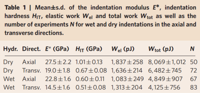
Reference: Schwiedrzik et al. Nature Materials 13, 740–747. (Reproduced with permission)
-
8.
Low-density mechanical metamaterials display enhanced load-bearing ability (with impressive strength-to-weight ratio). However, in-situ imaging during compression has revealed failure tends to initiate at the nodes or point of intersection for multiple struts (see Sect. 5.4). What could be the factors responsible for failure initiation at these points? What general precautions or modifications would you recommend while designing 3D architectures, so as to avoid premature failure?
-
9.
An SEM micrograph of a polymer microbeam subjected to mechanical loading is shown in the figure below.
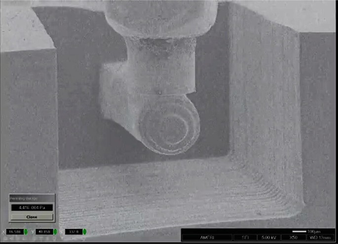
Figure: SEM micrograph of a polymer beam subjected to mechanical loading by a flat-ended punch. (The beam is 1.5 mm long and has a diameter of 300 μm). (Courtesy: Agarwal group (FIU), CELL-MET NSF Engineering Research Center)
-
(a)
Polymers are known to display time-dependent or viscoelastic mechanical behavior. Propose a detailed experimental scheme to investigate the viscoelastic response of this polymer specimen by “in-situ” testing (inside SEM). Your experimental scheme should be comprehensive and provide information pertaining to instrumentation, test parameters, real-time imaging, output, and analysis of the resultant data.
-
(b)
What could be the benefits of real-time imaging as compared to the conventional ex-situ approach? What are the challenges associated with in-situ measurement?
(Note: The chapter covered some examples of in-situ fatigue investigations. Seek inspiration from those examples to propose your experimental scheme.)
-
(a)
-
10.
The figure below (left) shows the SEM micrograph of a 3D printed polymeric honeycomb lattice. A flat-ended punch can be used to extract the overall mechanical response of the architecture. How can you measure the modulus of individual arms or nodes in the microstructure? Suggest a suitable in-situ (SEM) measurement technique and instrumentation.
Note: The individual arms have a width of ~2 μm.
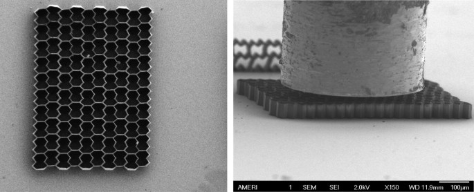
Figure: SEM micrograph of 3D printed honeycomb structure (left) and use of a flat-ended punch for in-situ compression inside SEM (right). (Courtesy: Agarwal group (FIU) and CELL-MET NSF Engineering Research Center)


Rights and permissions
Copyright information
© 2020 Springer Nature Switzerland AG
About this chapter

Cite this chapter
Nautiyal, P., Boesl, B., Agarwal, A. (2020). Application of In-Situ Mechanics Approach in Materials Science Problems. In: In-situ Mechanics of Materials. Springer, Cham. https://doi.org/10.1007/978-3-030-43320-8_5
Download citation
DOI: https://doi.org/10.1007/978-3-030-43320-8_5
Published:
Publisher Name: Springer, Cham
Print ISBN: 978-3-030-43319-2
Online ISBN: 978-3-030-43320-8
eBook Packages: Chemistry and Materials ScienceChemistry and Material Science (R0)