
Abstract
General Overview—The ITER project, established by an international agreement among seven Members (China, the European Union, India, Japan, Korea, the Russian Federation and the United States of America), is a critical step in the development of fusion energy: its role is to confirm the feasibility of exploiting magnetic confinement fusion for the production of energy for peaceful purposes by providing an integrated demonstration of the physics and technology required for a fusion power plant.
You have full access to this open access chapter, Download conference paper PDF
General Overview—The ITER project, established by an international agreement among seven Members (China, the European Union, India, Japan, Korea, the Russian Federation and the United States of America) Fig. 26.1, is a critical step in the development of fusion energy: its role is to confirm the feasibility of exploiting magnetic confinement fusion for the production of energy for peaceful purposes by providing an integrated demonstration of the physics and technology required for a fusion power plant.

ITER—International agreement among seven members
Rapid progress has been made in the design, manufacturing, construction and R&D activities, and, as shown in Fig. 26.2, the facility is now taking shape at St-Paul-lez-Durance in southern France.

Aerial view of the ITER site at St-Paul-lez-Durance with the construction of the Assembly Hall and Tokamak Complex
Fusion Technology is going beyond what is currently known and looks for Materials having strong mechanical capacities at very high temperatures in Normal/Accidental Scenarios and beyond design Basis Scenarios. Electromagnetic Loads, Disruption Loads, impulsive burst explosion loads, seismic loads and Aircraft Crash loads have to be considered in design loads combinations when Plasma Temperatures is above 150 million of degrees Centigrade and severe confinement is required to assure Primary Barrier decoupled from Plasma functional Scenario. It is difficult, but challenging. The major objective of the ITER project is to demonstrate that a future power producing fusion device can be maintained effectively and offer practical levels of plant availability.
Fusion powers the Sun and stars: two hydrogen nuclei combine, form a heavier nucleus and release energy (Fig. 26.3). Our objective is to reproduce this reaction on Earth.

Fusion reaction deuterium tritium
The process of nuclear fusion is summarized in the following steps:
-
Heat Deuterium-Tritium plasma to 150 million °C.
-
Confine and shape the plasma with magnetic fields.
-
Sustain a “burning plasma” with helium nuclei.
-
Transfer neutron energy to the metal walls.
-
Heat water → Steam → Electricity.
Nuclear Fusion Energy production advantages are listed:
-
Massive, continuous, baseload energy;
-
Safe, no meltdown possible;
-
No CO2 or other greenhouse gases;
-
No long-lived high-activity radioactive waste;
-
Unlimited fuel for millions of years.
ITER Mission (Fig. 26.4) is concentrated in getting demonstration to be able to produce industrial-scale fusion producing a “burning plasma” having:

ITER machine global assembly
-
Q ≥ 10—Gaining Factor;
-
50 MW of heating input—Required energy to work;
-
500 MW of thermal output—Energy produced.
The mechanism to assure nuclear fusion into the chamber (called Vacuum Vessel) is achieved running an electrical current in the DT gas in order to create a plasma status, heating with electromagnetic waves and inject high-energy neutrons.
The result: is to reach the temperature for fusion equal to 150,000,000 °C.
A giant magnetic cage is going to be built assembling together the central solenoid (13 m high and 1000 t), eighteen toroidal magnets (17 m high and 360 t each one) and six poloidal magnets (8 up to 24 m of diameter, 200 up to 400 t each one) Figs. 26.5 and 26.6.

Poloidal field coils

Integration PF/TF coils and VV-cage
The current situation in installation progress is summarized in the picture (Fig. 26.7).

ITER plant overview
Systems Description—Vacuum Vessel: The main component of ITER, where the fusion reaction takes place, is the Vacuum Vessel (VV), composed by the main vessel, the port structures and the VV supporting system (Fig. 26.8).

General overview of the Vacuum Vessel and Tokamak poloidal overview
The Vacuum Vessel is a torus-shaped double wall structure with shielding and cooling water between the shells (Fig. 26.9). The basic vessel design is an all-welded structure where the inner shell serves as the first confinement barrier for the in-vessel radioactive inventory. The Vacuum Vessel is divided into nine toroidal sectors joined by field welding using splice plates at the central vertical plane of alternate ports (of the odd numbers). The sectors are connected to each other with the splice plates with the provision for twofold cutting and re-welding.

Vacuum Vessel overall arrangement
At the upper level, there are 18 ports of a similar design. At the equatorial level, there are 14 regular equatorial ports and three ports for the neutral beam injection (NB ports). At the lower level, there are five ports for divertor cassette replacement and/or diagnostics (the divertor Remote Handling/diagnostic ports), and four ports for vacuum pumping (the cryopump ports). Between these ports, there are local penetrations for ELM coil penetrations, divertor piping, in-vessel viewing and glow discharge cleaning of the in-vessel components. The port structure is attached to the port stub (integral to the main vessel) and includes the port stub extension, and the port extension (normally equipped with the connected duct extended to the cryostat). The port components are connected to each other with the splice plates.
The main characteristics of the Vacuum Vessel are summarized in Table 26.1.
Water Cold Sinks: The Cooling Water system is designed to remove the high heat deposition on the Vacuum Vessel either during normal operation (the total heat deposition is non-uniformly deposited and mainly due to nuclear heating) or during off-normal operation (the decay heat of the VV and thermal radiation from the in-vessel components such as blanket and divertor—Fig. 26.10).

Vacuum Vessel water routing and water flow passage
The ITER Cooling Water System is composed of four main systems (Fig. 26.11):

Tokamak Cooling Water System (TCWS)
-
the Tokamak Cooling Water System (TCWS);
-
the Component Cooling Water System (CCWS);
-
the Chilled Water System (CHWS);
-
the Heat Rejection System (HRS).
The TCWS removes heat from the Vacuum Vessel (through the Vacuum Vessel Primary Heat Transfer System, VV-PHTS), from the in-Vacuum Vessel Components (through the Integrated loop of Blanket, Edge Localized Mode-Vertical Stabilization Coils, and Divertor PHTS, IBED-PHTS) and the Neutral Beam Injectors (through the NBI-PHTS).
The Tokamak Cooling Water System also employs some supporting systems such as the Draining and Refilling System (DRS), the Drying System (DYS) and the Chemical and Volume Control System (CVCS).
The Component Cooling Water System is an intermediate closed loop that transfers heat to the Heat Rejection System (HRS) for final disposal to the atmosphere. CCWS-1 also provides cooling for some other nuclear systems (e.g. Tritium Plant Systems components, etc.).
The non-nuclear systems (power supply, busbars, cryoplant, chillers etc.) are cooled by four independent trains CCWS-2A, 2B, 2C, 2D (based on pressure, temperature and water chemistry demanded by the systems) which again transfers heat to the HRS.
Two Chilled Water Systems (CHWSs) are also present: CHWS-H1 provides cooling for Protection Important Components (PICs) via direct air heat transfer, whilst CHWS-H2 provides cooling for non-PICs.
The Tokamak Cooling Water System, directly connected with Vacuum Vessel, has the following main functions:
-
remove heat deposited in the in-vessel components (FW/BLK and DIV PHTS components) and the VV and NBI PHTS components during a plasma pulse and rejects this heat to CCWS-1;
-
control the coolant temperature, flow rate and pressure for the in-vessel components VV and NBI during normal operation as required;
-
control differential temperature between in-vessel components and the VV during all modes of operation;
-
provide SIC signals to initiate drainage of the VV to the safety drain tanks during postulated Loss of Coolant Accident (LOCA) or Loss of Flow Accident (LOFA) events;
-
remove decay heat during normal operation from the in-vessel components and the VV after plasma shutdown;
-
provide decay heat removal by the VV PHTS after postulated loss of offsite power (LOOP) events;
-
provide the primary confinement boundary of the radioactive inventory of the TCWS PHTS coolant for postulated failures of in-vessel components;
-
measure the heat removed from the in-vessel components and VV to contribute to the determination of the overall fusion power balance.
The ITER vacuum vessel operates in normal operating condition at p ~ 0 MPa (vacuum) and in any case the maximum internal pressure shall be limited to 0.15 MPa absolute, in case of loss of coolant accident from the in-vessel components (coolant coming from the TCWS) or LOVA (loss of vacuum accident) event. In order to fulfil this Project Requirements the Vacuum Vessel has been equipped with an additional sub-system: the Vacuum Vessel Pressure Suppression System (VVPSS directly connected to VV).
In Fig. 26.12 plant layouts view of the Vacuum Vessel and the VVPSS.

Plant layout view of the VV and VVPSS
The sub-system includes four Vapor Suppression Tanks (VST), one Small LOCA Tank and three Large LOCA Tanks, containing enough water at room temperature to condense the steam resulting from the Design Basis coolant leaks into the Vacuum Vessel, thus limiting over-pressurization to 0.15 MPa absolute. The system can also be utilized in a variety of other situations, such as a simple loss of vacuum, to provide over pressure protection and enhanced confinement by maintaining low pressure in the system.
Four types of events are considered in the design of the VVPSS:
-
Type 1 event: Pure LOVA;
-
Type 2 event: Small Pure LOCA;
-
Type 3 event: Large Pure LOCA;
-
Type 4 event: Combination of LOVA and LOCA.
Event type 2, 3 and 4 are considered as Beyond Design Basis Accident (BDBA) when the amount of steam generated exceeds the condensation capacity of the Vapor Suppression Tanks (in case of failure of the isolation valves on TCWS).
Cryogenic Cold Sink: While the cold sink for VV is the TCWS, the cold sink for Magnets assuring the confinement function of plasma is the cryogenic system. The purpose of the ITER cryogenic system is to provide the required operational conditions for the magnet system, vacuum system and small users like diagnostics. The magnet system consists of superconducting magnets coils, structure and current leads, and is supported by 80 K thermal shields system. The vacuum system consists of cryo-pumps for torus and cryostat, cryo-pumps for Neutral Beam Injection (NBI) and Pellet Injection System (PIS). The users of the cryogenic system require helium cryogen at temperature levels of 4.5, 50 and 80 K and nitrogen at either 80 K or ambient temperature. The cryogenic system needs to satisfy all operational modes of the users at various stages of plasma operation. To satisfy the operational modes and resulting requirements, the ITER cryogenic system has been divided according to the ITER Geographical Breakdown System (GBS) in two different locations namely the cryoplant System (in cryoplant buildings and cryo-bridge) and the cryo-distribution system (in the Tokamak).
The ITER cryogenic system, see Fig. 26.13, has to guarantee stable operation conditions for the magnets and cryosorption panels over a wide range of plasma scenarios ranging from short (~100 s) plasma pulses with enlarged fusion power (700 MW) to long plasma burn times (3000 s) at reduced fusion power of 365 MW, whereas the baseline is 500 MW for 400 s.

Cryogenic system global architecture
As one of the world’s largest cryogenic infrastructure, see Figs. 26.14 and 26.15, the ITER cryoplant will provide an average cooling power of 75 kW at 4.5 K during plasma experiments and up to 87 kW in pure refrigeration mode through three LHe plants. For the thermal shield of the Tokamak and cryo-distribution, two 80 K helium loops with an average capacity of 40 kW equivalents at 4.5 K (2 × 4 kg/s loops in between 80 and 100 K) will be installed.

Cryoplant system 3D layout

Comparison of ITER cryo-plant helium cooling capacities
Two liquid nitrogen (LN2) refrigerators with a maximum capacity of 1300 kW at 80 K will support the nitrogen pre-cooling system of all helium plants. ITER will have its own nitrogen production facility on site, provided by a nitrogen generator of ~1550 N m3/h capacity for blanketing, leaks, purifier, regeneration of dryers as well as a redundancy in case of instrument air network failure.
An impurity processing system recovers and purifies helium from safety valves and other open circuit users. A heat recovery system (HRS) will recover up to 12 MW of heat from the cooling water circuits of the screw compressors for heating of the ITER buildings.
Storage and recovery of the helium inventory is managed via warm and cold (80 and 4.5 K) helium tanks.
ITER will have to store an overall helium inventory of 27 t. The storage system has been optimized and its cost reduced with the replacement of part of the warm storage vessels with a 175 m3 LHe dewar. The storages, including those for large volumes of gaseous and liquid nitrogen, are summarized in Table 26.2 and its layout in Fig. 26.16.

Cryogenic system installed in buildings 51/52
For the first time a large and distributed cryogenic system has to consider the constraint of a nuclear installation while aiming at maximizing the efficiency, flexibility, availability and reliability of operation required to demonstrate the economic viability of fusion for future energy production. As a nuclear installation, the ITER project is under the French Quality Order 1984 (French decree relating to the quality of design, construction and operation) which has been rolled-out to contractors and sub-contractors. Codes (mainly for pressure vessels) are imposed and strictly followed unless proper counter measure could be implemented. One of the main issue for IO as a nuclear operator is maintenance of all vacuum insulated pressure vessels which forces the design to take all measure to assure or avoid such activities of periodic inspections and requalifications.
A Reliability Availability Maintainability Inspectability (RAMI) analysis is developed and detailed along all design phases, with contractors and re-integrated to IO overall RAMI analysis.
For protection of investment as well as personal, Hazard and Operability (HAZOP) and Safety Integrity Level (SIL) studies are systematically conducted.
In order to meet RAMI, HAZOP and SIL requirements, the cryoplant technical specification refers to the European or International standard such as EN ISO 10440-1 for rotary-type positive-displacement compressor or EN ISO 10438 for lubrication, shaft-sealing and control-oil systems and auxiliaries. All rotating machineries have to follow either an ISO standard or its equivalent from the American Petroleum Institute (API). The heat exchanger will follow the TEMA (Tubular Exchanger Manufacturer Association) or ALPEMA (Aluminium Plate Fin Exchanger Manufacturer Association) standards.
Maintenance and In Service Inspection (ISI)—The World of Remote handling system and Robotics: A major objective of the ITER project is to demonstrate that a future power producing fusion device can be maintained effectively and offer practical levels of plant availability. During its operational lifetime, many systems of the ITER machine will require maintenance and modification; this can be achieved using remote handling methods. The need for timely, safe and effective remote operations on a machine as complex as ITER and within one of the world’s most hostile remote handling environments represents a major challenge at every level of the ITER Project organization, engineering and technology. Remote handling (RH) is the synergistic combination of technology and engineering management systems (Fig. 26.17) to enable operators to safely, reliably and repeatedly perform manipulation of items without being in personal contact with those items. ITER mission requires scheduled upgrades of the machine, by means of exchanging internal components, executing scheduled and unscheduled maintenance and/or repair operations.

Engineering innovation—robotics
To accomplish such tasks, ITER has adopted a RH maintenance plan (IRHMP). This is based on the maintenance system (IMS) equipment, on the IMS facilities (hot cell, test stand) and on a set of operational procedures. The RH approach required for a fusion device like ITER is characterized by: (a) geometrically complex working environment, (b) large, heavy components with close tolerance fits, (c) limited access through narrow ports; (d) poor visibility, (e) the RH equipment comprises combination of large transporters, specialised end-effectors (including teleoperated manipulators) and tooling, (f) relatively long distance between reactor and hot cell, (g) hot cell dimensions and functions. To complicate matters further, the environmental conditions in which the RH equipment is required to operate are: (a) ultra high vacuum clean conditions, (b) high gamma radiation, (c) contamination, e.g. beryllium dust, tritiated carbon dust, gaseous tritium and activated tungsten dust, (d) some level of magnetic field. The ITER Remote Handling Management Plan (IRHMP) (being developed, Fig. 26.18) will be the reference for the management of the specification, design, procurement and operation of all the ITER remote handling equipment and facilities, including the RH compatibility of ITER components.

Logic of the ITER IRHMP and its relation with the IMS
The objectives of the IRHMP are to: (a) establish and manage the ITER requirements for in-vessel components maintenance and upgrade, on the basis of the IMS equipment and facilities availability, (b) define the IMS performance parameters and operational limits, (c) define the IMS deployment strategy for planned and unplanned maintenance based on the IMS operational & safety limits and on the established machine experimental program, (d) develop an IMS information package, to allow good planning of in-vessel components’ maintenance & upgrade campaigns, (e) define and facilitate the use of best practice and standards for the specification, design and manufacture of the IMS, (f) define the best practice and standards for the design, manufacture and qualification of RH compatible ITER components, (g) define the best practice and standards to be used for the preparation and implementation of RH operations, (h) define and control the RH classification of ITER components.
The blanket RH equipment design has progressed in the JA-DA to include the CATIA modeling of the blanket In Vessel Transporter (IVT) system and its deployment process simulation (Figs. 26.19, 26.20 and 26.21). The process requires using dedicated, multiple pairs of IVT transfer casks (main IVT cask and intermediate IVT cask) required for the support of the IVT rail, for the deployment of the IVT vehicle/manipulator system, for the system support services and for the blanket modules exchange system. Some key technology aspects have also been or will be validated through a dedicated R&D program (manipulator gears lubrication, IVT rail hinge mechanism, cable handling, etc.), as well as the development of a simulator for the positioning control of the IVT vehicle and gripper.

Blanket RH 3D simulation

Blanket RH trials using the IVT and manipulator

The equatorial transfer cask (a) and the divertor transfer cask (b)
Electrical Networks and electrical conversion: The network that will control the power supply to the ITER plant basically consists of two parts: a network for steady state and a network for pulsed operations (Fig. 26.22). The steady state electrical network (SSEN) supplies the power needed to operate the plant including offices and the operational facilities. The major consumers are the cooling water and cryogenic systems requiring together about 80% of the total demand of 120 MW. The power is taken from the 400 kV network that winds across Southern France past Cadarache. The ITER pulsed power electrical network (PPEN) is also connected to the powerful high-voltage grid, it provides the large pulsed power needed to supply the superconducting coils and the heating and current drive (H&CD) systems. The AC power is received from the 400 kV high-voltage grid and transformed to intermediate levels (66 and 22 kV) via 3 step-down transformers. The total peak active pulsed power demand will be limited to 500 MW. This includes power required to operate and control the Poloidal Field coils, the power needed for the positioning and the shape control of the plasma current, and including the vertical stabilization, and power to supply the H&CD systems.

Electrical power distribution
A so called “reactive power compensation” system, one of the largest ever built so far, will make sure that the power taken off the grid does not exceed the level impose by the French grid operator.
The pulsed power supply is summarized in the attached scheme (Fig. 26.23).

Pulsed Power Supply
The main function of the Central Solenoid and Poloidal Field AC/DC converters are the following:
-
Power converters supply the magnets. However this is not the ultimate their main function. The main function is to control the plasma current and the plasma wall gaps.
-
Using the Coil Power Supply Converters, the CS and PF coil currents are controlled and affect the configuration of the magnetic flux, which determines the plasma shape and position as well as the plasma current (Fig. 26.24).
Fig. 26.24 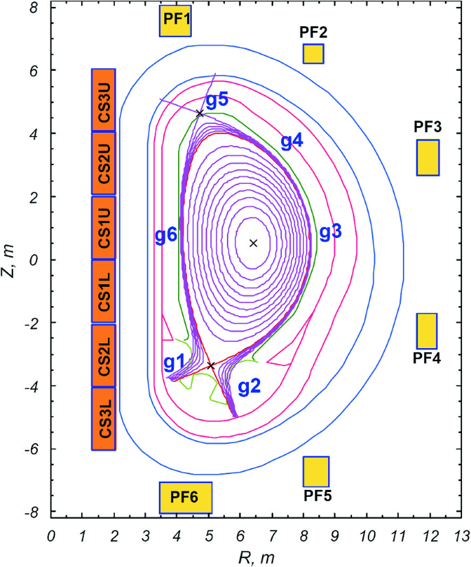
Plasma shape and position

The Coil Power Supply system is a large and intricate system that includes challenges, not only during the design and qualification, but also in the installation of the components into a very complex configuration:
-
About 2 GVA installed power of high current (up to 68 kA), thyristor based, 4 quadrants, ac/dc power converters (most likely the world largest, high current conversion plant);
-
80 kA, 2.4 kV Switching Power Converters, which are quite beyond the industry practices;
-
750 Mvar, Static Var Compensator and Harmonic Filtering system, connected to 66 kV ac (the largest in Europe, most likely the 3rd largest in the world);
-
5 km bipolar busbars (max. cross-section: 420 × 270 mm);
-
high reliable circuit breakers capable to carrying and interrupting up to 70 kA dc currents, and large resistors capable of discharging up to 50 GJ in about 30 s (first of its kind and key items for safety and investment protection).
ITER Vacuum System: The vacuum system will be one of the largest, most complex vacuum systems ever to be built. There are a number of large volume systems including: the cryostat (~8500 m3), the torus (~1330 m3), the neutral beam injectors (~180 m3 each) and a number of lower volume systems including: the service vacuum system, diagnostic systems, and electron cyclotron transmission lines. In total there are more than 400 vacuum pumps of 10 different technologies required to pump the systems. The most demanding vacuum pumping applications are served by 18 large cryogenic pumps of 3 distinct custom designs. All of the vacuum systems are progressing from design, validation and into manufacturing (Fig. 26.25).

ITER vacuum system global view
The ITER vacuum vessel and cryostat are to be directly pumped by a total of 8 cylindrical cryo-sorption pumps (Fig. 26.26) with integral 800 mm all metal vacuum valves.

Torus and cryostat cryo-pump (1.8 m diameter)
The “build-to-print” design of these pumps is complete and the first pump is well advanced in manufacturing. All component parts have been manufactured, qualified and are now being assembled with completion expected in 2017. The 8 t flange of this cryopump, known as the “pump plug”, is seen in Fig. 26.27.

Machined flange of the first Torus Cryo-pump
The ITER neutral beam systems are each to be pumped by a pair of open structure panel style cryo-sorption pumps (Fig. 26.28) with a length of 8 m, and height of 2.8 m. They will achieve a pumping speed of 4500 m3/s for hydrogen. The final design of these pumps has involved development of new fabrication methods so as to significantly reduce the cost and manufacturing time for the thousands of cryo-panels and thermal shields within the pumps. The procurement process of the first pump, to the ITER “build-to-print” design, has commenced, this first pump is destined for the ITER neutral beam test facility (MITICA) in Padua.

Nuetral injection cryo-pump
Conclusion—ITER is a fantastic challenging adventure for scientists, engineering and physics. It is the dream of each of us to achieve the highest level of knowledge in technology and scientific applications. ITER is a fantastic opportunity to produce transversal technologies to be applied in Medicine, aeronautics, aerospace, waste management, nuclear applications.
For all these reasons the Project belongs to all of us: we cannot fail in this fantastic effort.
Let us work together to achieve with contributions generated all over the World the primary objective to get ITER Plant getting First Plasma within December 2025 and Nuclear Phase within 2035.
It is the way to get the Sun on Earth.
We are all sure: ITER is the way to a new, clean, safe and nearly unlimited energy.
Author information
Authors and Affiliations
Corresponding author
Editor information
Editors and Affiliations
Rights and permissions
Open Access This chapter is licensed under the terms of the Creative Commons Attribution 4.0 International License (http://creativecommons.org/licenses/by/4.0/), which permits use, sharing, adaptation, distribution and reproduction in any medium or format, as long as you give appropriate credit to the original author(s) and the source, provide a link to the Creative Commons license and indicate if changes were made.
The images or other third party material in this chapter are included in the chapter's Creative Commons license, unless indicated otherwise in a credit line to the material. If material is not included in the chapter's Creative Commons license and your intended use is not permitted by statutory regulation or exceeds the permitted use, you will need to obtain permission directly from the copyright holder.
Copyright information
© 2020 The Author(s)
About this paper

Cite this paper
Orlandi, S. (2020). ITER Project: International Cooperation and Energy Investment. In: Maiani, L., Jeanloz, R., Lowenthal, M., Plastino, W. (eds) International Cooperation for Enhancing Nuclear Safety, Security, Safeguards and Non-proliferation. Springer Proceedings in Physics, vol 243. Springer, Cham. https://doi.org/10.1007/978-3-030-42913-3_26
Download citation
DOI: https://doi.org/10.1007/978-3-030-42913-3_26
Published:
Publisher Name: Springer, Cham
Print ISBN: 978-3-030-42912-6
Online ISBN: 978-3-030-42913-3
eBook Packages: Physics and AstronomyPhysics and Astronomy (R0)