
Abstract
This paper reports the research on the complex process of implementing modular product structures in a Product Lifecycle Management (PLM) system. There are many challenges in implementing the system. One main challenge is organising or mapping existing product data and migrating it to the new PLM system. Companies often use a PLM tool for management of CAD files, documents and drawings, but they do not take advantage of the full potential of the PLM system to support the development activities of modular products. Product data management tools are used mainly for product CAD data management and PLM systems support by automating and managing some of the operational complexity of modular product design. The aim of this research is to propose a data model that can be used for implementing modular product structures in a PLM system and a tool that can formalise the existing data so as to migrate it into the PLM system.
You have full access to this open access chapter, Download conference paper PDF
Keywords
1 Introduction
PLM systems are now widely used in companies to manage product development and service processes from beginning to life cycle end [1]. Among the major changes in product development, the lifecycle management and time to market of new products are the big issues. Reducing the development cycle is always a challenge. There seems to have a general transformation in the industry in the last two decades from developing products in independent projects to the development of product families. Architecture based product development is one initiative in the product development area to address the changed way of developing products, which focuses on the design of product ranges instead of individual products, and by reuse of knowledge, components, processes and utilization of economies of scale in many of the activities that are necessary to provide products for customers. Product architecture development can be done through Modularization of commonality among different variants. Modularization of product structures can serve as a means to provide a variety of products that are needed for customers, and at the same time re-use sub-solutions across different products to improve time-to-market [2]. To achieve this PLM tool should be implemented that will facilitate the modular structures and migrate the existing product data into the PLM system.
2 PLM System Architecture and Its Implementation Methods
By definition, PLM integrates product information, people and knowledge by controlling a company’s processes [3]. The PLM concept holds the promise of seamlessly integrating all the information involved throughout all phases of a product’s lifecycle to everyone in an organization at every managerial and technical level, along with key suppliers and customers. As such, PLM systems need the capability to serve up the information referred to the above, and they need to ensure the cohesion and traceability of product data. For an enterprise to be successful in today’s and tomorrow’s global markets, PLM is not an option, it is a competitive necessity [4].
A critical aspect of PLM systems is their product information modelling architecture. The traditional hierarchical approach to building software tools presents a dangerous potential pitfall: if PLM systems continue to access product information via Product Data Management (PDM) systems which, in turn, obtain geometric descriptions from Computer-Aided Design (CAD) systems, the information that becomes available will only be the CAD data. This is what most of the companies are using for. CAD data is a tiny portion of product information or knowledge [5]. In this research, a different approach is proposed in serving up information to PLM systems: a single PLM system support framework for product information that can access, store, serve and reuse all the product information throughout the entire product lifecycle. The full PLM system functionality can be achieved by the specific components: a Foundation Technologies (Infrastructure); Core functions; a set of business Applications; and a set of Business solutions [6].
The main elements of a typical PLM system architecture include PLM server, Web server, Mail server, Indexing server, Database server and few optional elements like Enterprise directory and administrative directory. The Java-based PLM server is the application layer of the system and provides system logic for behaviour and data element relationships. The Web server enables Web connectivity, giving Web-centric behaviour. These two elements comprise the technology core of the PLM solution. Client machines, which are the computers used by the user community, only require the latest browsers and network connectivity to access data and execute tasks. Since most PLM systems are Web-based applications, accessing information is as simple and familiar as browsing the Internet. Lightweight Directory Access Protocol (LDAP) server or Mail server to reference user, group, and organizational data. Most PLM systems also come bundled with a standalone LDAP server, the system Directory Server. You may also configure to access an existing corporate LDAP server, such as Microsoft’s Active Directory. A database server, such as an Oracle server, is used as the repository for metadata. Content files may also be stored in the database, but they are often referenced and stored elsewhere in a file vault. The database server, Windchill server, Web server, and client machines, establish a three-tier architecture, which is scalable and more accessible to manage than traditional client-server environments. File vaulting is the process of storing content on an external file system, as opposed to BLOBS (Binary Large Objects) in the Windchill database. By default, contents are stored inside the database. However, file vaulting manages data on an external file system in folders and subfolders and reduces the time for uploading and downloading data. The storage location of content files is transparent to the user, so user operations do not have to be modified.
3 Data Model for Modular Product Structure Implementation
3.1 Modular Product Structure
Modular products consist of detachable modules, which can be manufactured, assembled, and serviced separately. Some of the modules may be reusable, recyclable or re-manufacturable upon product retirement. Thus, modular design can provide benefits to many aspects of the product life cycle [7]. Product modularity is primarily seen as a product structuring concept, in which the product is decomposed into smaller, more manageable chunks (modules) in order to better manage design and manufacturing complexity. The most common way this is done is by the decomposition of the product down to component level and then a grouping of the components to form modules. Modularity is a concept and process of clustering the independent components into logical units that are relatively independent of each other in functions [8]. Modular design methods that have been focused on include function-based [9, 10], manufacturing or assembly [11], and mass customization [12]. Ulrich and Tung [13] gave a summary of different types of modularity and their advantages and disadvantages.
Modularity allows the designer to control the degree to which changes in product maintenance and service processes affect the product design. By promoting interchangeability, modularity also gives designers more flexibility, with decreased cycle time, to meet these changing processes. The flexibility that modularity offers is increasingly vital as uncertainty in service requirements (due to new diagnostic and repair technology and ever-changing warranty agreements) increase. This flexibility allows some design decisions to be delayed because they have a lower impact on the total product. Controlling the effects of changes and being flexible in responding to changes are the benefits of modularity. A compliant product can more readily adapt to a late influx of service technology or a new shift in service strategy. To implement the modular product structure in PLM, a data model is proposed which is the primary task to implement the methodology. The object types and their relations are illustrated in Fig. 1.

Data model for modular product structure in PLM
The PLM system used in this research is Windchill which supports a number of different types of objects: Display object type ‘PART’ is used for all parts in the product and its Object Class is called WTPart. The product is represented as ‘End Item’ for display in the system and its Object Class is also called WTPart with an attribute as End Item and values Yes/No. CAD models are called as CAD Documents for display purpose and its Object Class is called EPMDocument. The objects have been carefully defined to provide the functionality of the multiple structure views, yet able to handle the interdependencies as systems split modules, modules containing elements belonging to different systems, and interfaces between different system elements.
The data model shown in Fig. 1 is proposed to implement in PLM system which facilitates to structure products with the modular methodology. The product is the final End Item that the company will produce. This End item can be of 3 types, a Pre-Configured product, Configurable Product or Engineering to Order product. The soft type object in the system is called an End Item. As mentioned earlier this is recognized with an attribute that can be easily searchable either within the folder or in Global search. The proposed methodology is to have a single folder for each family of products. In the sponsoring company example, all products that are produced for 15 L Genset (Genset is the name of the final product). For clarity in this family, there are 2 types of configurable products and several pre-configurable products. Engineer TO Order (ETO) products are created depending on customers’ requirements.
3.2 PLM Objects and Their Relations
The End Item or Product will have a Used-By relation with all the Modules called Variants in PLM terminology. Each variant may consist of one or more options depending on the requirements. All Modules will have ‘Uses’ relationship to all assemblies. Each option in the module shall have an assembly with Uses relationship. An assembly is the combination of physical components representing the module in three aspects, i.e., Form, Fit and Function. The assembly will have ‘Owner’ relation with the CAD object. There will be only one Owner for each WTPart and this is an essential object that defines the assembly. Other documents can be added as an attachment if required, but only one object will be the Owner. The CAD assembly is always defined by a CAD drawing and this will have Reference or Child relationship. The CAD assembly will the parent from which the CAD Drawing is created, and it is a child. The assembly will have at least one part and as more as hundred if required. The parts under an assembly are called Bill Of Material (BOM). Since the initial BOM is defined by engineering, this is known as Engineering Bill Of Materials (EBOM). As progressing this BOM is transferred to downstream functions it will be changed or converted according to their needs.
The Part is the single level item and it can be on its own in the product or it can be part of an assembly. This represents a manufacturable or purchased item that is used at a different level in the product. Part will have Owner relation with CAD object similar assembly explained earlier. The CAD models can have CAD drawing to define the CAD part that will have a Reference or Content relationship. Another object mentioned in the data model is Drawing Specification. This object act as a space holder for storing the CAD drawing in PDF format while that is in the process of releasing. This will only represent the CAD drawing, does not contain any reference to other specifications attached to WTPart. The WTPart can have many specifications attached likewise material specifications with which the part would be made, standards specification to which the part would comply, and Regulation specifications the part would comply to. The drawing specification does not reflect all these references.
Another document type used in the data model is part drawing. This is a place holder for In-Process document and final released drawing in PDF format. PLM system has got the ability to create an in-process document while the objects are in the Change Management process. Product containers will be created for each generic Product Context. The products, i.e., End Items are stored in these containers which are represented with a folder figure in the data model. Under each product container, there are multiple folders to store product information. Each folder can represent different objects types, for example, Change Management objects, CAD objects, WT Part objects, Specifications objects, End Items (Products), Project Management data and Manufacturing data. Since the objects relate to the relationships proposed earlier, they will have good traceability even though they are stored in different locations in the system. The proposed data model will bring all product information under one system with good parametric relationships between the objects created. This model would work with most PLM systems in the market. This data model is tested in the PTC Windchill PLM system. The next challenge is how to arrange the legacy, i.e., existing product data. For this, a tool has been designed and explained which is discussed below.
4 Product Data Preparation Methodology and Migration Tool Design
One of the biggest challenges in implementing any new PLM systems in the industry is to deal with existing product data or knowledge. All PLM systems provide tools for data migration, but they are mainly focused on AS-IS process, do not have many flexible methods to adopt any specific needs of companies. This is mainly because the tools from the software are developed for general-purpose, not for any specific industry or product types, which leads to having out of system solution.
4.1 Product Data Preparation Concept
Data translation and migration from one system to other system is increasingly difficult based on the volume of data, quality, and complexity. Automation of data translation and validations at each step helps to achieve a higher return on investment. Detailed planning, analysis, selection and prioritization of the data are some of the key parameters for successful data migration. It is important to try to establish the value of the data that is considered for conversion and the scope of that effort [14]. A sample data of few products are collected from the sponsoring company. The well-defined product structure of this product type is studied and incorporated into the tool.
In the industrial investigation from the sponsor company, all the configurable product structure is created in an Excel document as the part of new product development and the same is maintained manually when there are changes to the structure. This is the main document for product structure information for all products. Only the top four levels of the product structure are maintained in this document, the rest of all intended levels of product structure are maintained in Enterprise Resource Planning (ERP) system. Some levels of structures are created and maintained in CAD/CDM systems and product configurator depending on the requirements of the system. For example, the product configurator function is to configure the product that the system does not require any manufacturing or CAD product information. Each system has got its own requirements to meet its functionality and a typical system will have input information from its preceding system and generates required output for the following system. The product data is created by CAD systems stored in the Product Data Management (PDM) system and the information needed for the manufacturing process is the interfaced to ERP system. Product data required for configuration is interfaced from the ERP system. Some ERP systems have a configuration module within its system for example Oracle. Figure 2 shows the relationships of product structure with different systems and how the product data is represented in their systems.

Product structure connections with different systems along with BOM types
Product data stored in PDM is in the form of EBOM, it is stored in ERP system in the form of MBOM for manufacturing, in the form of CBOM in configurator and in the form of SBOM for service function. For building the module product structure and structuring the product data for migration, a tool has been proposed. For this methodology data from 3 systems are collected and by using data mining techniques [15] the product data will be migrated to PLM in the earlier proposed data model methodology.
4.2 Product Data Migration Tool Design
To demonstrate the proposed data model described above, a tool has been designed using VBA (Visual Basic) as the Front End and Excel like the back-end data collection. The tool is named as ‘Integrated Product Modular Structure’. Out-Of-The-Box data migration functionality of most existing PLM systems in the market does not provide any mechanism to create a modular product structure. The proposed tool is designed to demonstrate the methodology with small sample data. The following steps will define the operation of this tool (as shown in Fig. 3).

The tool for creating modular product structure from legacy data [16]
-
Step 1. The 3 boxes on the left of Fig. 3 show the list of existing products, modules/features and options or variants as per the modular product structure. For example, Product 1 will have Engine module with Engine Kits as an option. The tool can also create new products, features, and options if required. This can be done using the bottom-left options available in the form shown above. Once the required features and options are created, users can create a new product and select the level one module or features and level two options to create a modular structure. The main function of this tool is to create a product with modular product structure including features and options making metadata connections in the background using the Visual Basic code written.
-
Step 2. The existing product data is collected from three different systems, i.e., product data management, enterprise resource planning and product configurator. Since the company has been selling products for many years, ERP systems must have product BOM in some format, either in manufacturing BOM or in some other form. A configurator has overloaded BOM of the product, with rules to drive the configurable product (CBOM). From the sponsor company data, these are the two areas where the product BOM is maintained for order management and other many operations. The CAD data which is the starting point of the product development process is maintained in many locations, but mainly on the CAD data management system called Windchill PDMLink (in the sponsor company). Data from all these systems are imported into this tool. The 3 boxes on the right side of Fig. 3 show the data from 3 systems.
-
Step 3. Frame ‘New Folder Creation’ is used to create the folder structure for storing product physical data in a respective folder and make relations to corresponding parts or assemblies or options or features. Folder/containers will be created for different object types for storing product information. For example, all the CAD objects are stored in one folder, Parts are stored in another, analysis data as attachments are stored in another folder. But the relations explained in the data model will keep them connected from traceability perspective.
-
Step 4. Once the above 3 steps are done, the top 3 levels of product structure are built, the parent-child relations would have been built in the background. This step is to connect the design information level product data, i.e., the CAD data. From the example discussed in Step 1, the relationship was built up to option level Engine Kits. Now in this step, the appropriate assembly or assemblies will be selected from the data populated in the CAD/CDM list. The program will allow selecting more than one assembly if there is more than one option for that variant. By selecting appropriate assembly/assemblies, the system will generate the next level, i.e., the 4th level of information to the product structure. This selection will be validated from the ERP and Configurator systems that are correct or not for the existing products. These can be achieved from the metadata relations existing in their system and migrate it to the tool. This methodology is proposed taking the assumption that there are logical references, i.e., either the classification or attributes that are driving the three systems. The output of this step is having the 4 levels of product structure build and collection of current location path of the files in the legacy systems. Once this data is available, an in-built logic will define the location of the object in the target PLM system.
-
Step 5. Data from one system is retrieved into export files, then while passing through integration module it is converted into a format that is understandable by another system after removing the redundant information which is challenging [17]. In this step, the formatted data from the integrated tool VBA and Excel is exported in the XLM data format. First, a schema based on XML source data will be created. The schema defines the structure of the XML file that replicates product structure data format. Figure 4 shows the pictorial representation of this process. This must be done outside Excel and the file is saved as a schema.xml file. From the formalised Excel product data file, open the schema and export the data from excel to XML format. This will be the source file for importing the data into the PLM system. This process only covers the metadata, not the physical data which is residing in the data vault. Migrating physical data is not considered in this paper. That is considered for future study.
Fig. 4. 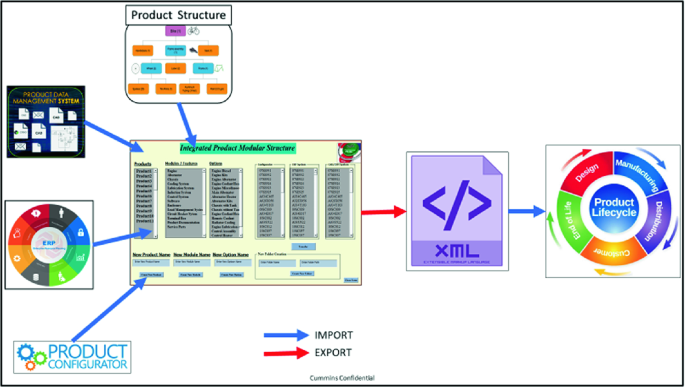
Product data translation mechanism

5 Conclusions
The manufacturing industry has been evolving for so many years, and there is an immense amount of product data generated in the process of product development. Modular product structures have been developed for many years and found many benefits in implementing this methodology. Most companies adapted this methodology on the process side while very few attempted to do it in PLM systems. The proposed methodology in this research gives an opportunity to prepare the data model and prepare the product data that can be structured and transfer the data in the structure format which will enable easy manageability, integrity, consistency and traceability of the product information in the whole lifecycle. The data mining process of the product data between the engineering information systems is an achievable approach which will give seamless connection of data integrity which enables the data flow process smooth in future product changes. With the developed tool, engineers should be able to build Modular Product Structures with PLM systems and connect the product knowledge to the structure which can be traceable as and when needed for future product development. Future work from this study is to develop an application of the proposed methodology to handle a large amount of product data. The developed tool has some limitations in handling big data for demonstrations using VB and Excel.
References
Mourad, M., Farouk, B., Benoit, E., Abd-El-Kader, S.: System Engineering and PLM as an integrated approach for industry collaboration management. In: IFAC Symposium, pp. 135–140 (2012)
Bruun, H.P.L., Mortensen, N.H., Harlou, U., Worosch, M., Proschowsky, M.: PLM system support for modular product development. Comput. Ind. 67, 97–111 (2015)
Bedolla, J.S., Ricci, F., Gomez, J.M., Chiabert, P.: Fostering PLM implementation in SMEs: modelling and managing verification processes. In: International Federation of Automatic Control, pp. 1762–1765 (2013)
Sudarsan, R., Fenves, S.J., Sriram, R.D., Wang, F.: A product information modeling framework for product lifecycle management. Comput.-Aided Des. 37, 1399–1411 (2005)
Silventoinen, A., Jorma P., Hannele, L.: A roadmap for product lifecycle management implementation in SMEs. In: The XX ISPIM Conference, Research Gate (2009)
CIMdata Inc: Product Lifecycle Management Empowering the Future of Business. CIMdata Inc., Michigan (2002)
Gu, P., Sosale, S.: Product modularization for life cycle engineering. Robot. Comput. Integr. Manuf. 15, 387–401 (1999)
Yua, S., Yanga, Q., Taoa, J., Tiana, X., Yinb, F.: Product modular design incorporating life cycle issues - Group Genetic Algorithm (GGA) based method. J. Cleaner Prod. 19, 1016–1032 (2011)
Huang, C.K.: Modularity in design of products and systems. IEEE Trans. Syst. Man Cybern. Syst. Hum. Part A 28(1), 66–77 (1998)
Krenga, V.B., Leeb, T.P.: Modular product design with grouping genetic algorithm—a case study. Comput. Ind. Eng. 46, 443–460 (2004)
Bryan, A.K.: Co-evolution of product families and assembly systems. CIRP Ann.-Manuf. Technol. 56(1), 41–44 (2007)
Mikkola, J.G.: Managing modularity of product architecture: toward an integrated theory. IEEE Trans. Eng. Manag. 50(2), 204–218 (2003)
Ulrich, K.T.: Fundamentals of Product Modularity, vol. 3973-80. American Society of Mechanical Engineers, Design Engineering Division DE (1991)
Murthy, K.: Best Practices for CAD Data Migration. https://www.hcltech.com/…/Best_practices_for_CAD_Data_Migration_v01_2.pd. Accessed 2011/16/2018
Jiawei, H., Kamber, M., Pei, J.: DataMining: Concepts and Techniques, 3rd edn. Elsevier Inc., Waltham (2012)
Giddaluru, M.P., Gao, J., Bhatti, R.: Integrating product knowledge with modular product structures in PLM. In: International Conference on Innovative Design and Manufacturing. ICIDM, Milan (2017)
Ostroukh, A.V., Gusenitsa, D.O., Golubkova, V.B., Yurchik, P.F.: Integration of PDM and ERP systems within a unified information space of an enterprise. J. Comput. Eng. 16, 31–33 (2014)
Author information
Authors and Affiliations
Corresponding authors
Editor information
Editors and Affiliations
Rights and permissions
Copyright information
© 2019 IFIP International Federation for Information Processing
About this paper

Cite this paper
Giddaluru, M.P., Gao, J. (2019). A Data Preparation and Migration Framework for Implementing Modular Product Structures in PLM. In: Fortin, C., Rivest, L., Bernard, A., Bouras, A. (eds) Product Lifecycle Management in the Digital Twin Era. PLM 2019. IFIP Advances in Information and Communication Technology, vol 565. Springer, Cham. https://doi.org/10.1007/978-3-030-42250-9_19
Download citation
DOI: https://doi.org/10.1007/978-3-030-42250-9_19
Published:
Publisher Name: Springer, Cham
Print ISBN: 978-3-030-42249-3
Online ISBN: 978-3-030-42250-9
eBook Packages: Computer ScienceComputer Science (R0)