
Abstract
Our discussion up to this point has been focusing on signalized intersections with isolated operation, meaning we only consider strategies to improve the operation of a single intersection. In this chapter, we extend our discussion to multiple intersections such that these intersections work together to achieve desired control goals, e.g., to improve traffic operation in certain direction(s). Such a strategy is called traffic signal coordination.
This is a preview of subscription content, log in via an institution.
Buying options
Tax calculation will be finalised at checkout
Purchases are for personal use only
Learn about institutional subscriptionsNotes
- 1.
In areas where vehicles are not allowed to enter an intersection during YELLOW signal, the splits represent durations of GREEN signal and YELLOW + RED signal, respectively.
References
Webster, F. Traffic signal settings. Road Research Technical Paper No. 39.
Kell, J.H. (1956). Coordination of Fixed-Time Traffic Signals, Lecture notes for Fundamentals of Traffic Engineering. University of California-Berkeley, Institute of Transportation and Traffic Engineering
Schiffman, M. (1972, January). Closed network signal timing. Traffic Engineering, 42(4), 35–37.
Author information
Authors and Affiliations
End-of-Chapter Problems
End-of-Chapter Problems
-
1.
(Progression in favor of one-way traffic with nonuniform block spacing) The following is a series of exercises on the construction of time-space diagrams based on the major route with five intersection streets, see the figure below.
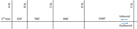
Reading from left to right, the green time as percent of cycle (the split) for each intersection is 60%, 65%, 55%, and 50%, respectively.
To construct a time-space diagram, use a sheet of 11″ × 16½″ graph paper in portrait orientation ruled 10 × 10 to the inch. Draw a vertical “space” scale on the left and a horizontal “time” scale across the bottom. Leave a 1″ margin on the left and on the bottom.
Label your time scale in units of cycle time, not in seconds. Use one cycle length equals 2″ so that four cycles can be shown. The vertical scale is 15″ long. With 1″ margin on each side, there are 13″ left to lay out a section of 1st Ave. of length 320′ + 760′ + 840′ + 1440′ = 3360′. Therefore, 3360′/13″ = 258 ft per inch, and you will want to lay out the block lengths as follows:
A St.–B. St.: 320′/258 = 1.24″
B St.–C. St.: 760′/258 = 2.94″
A St.–B. St.: 840′/258 = 3.26″
A St.–B. St.:1440′/258 = 5.58″
Total 13.02″
At certain time of the day, noticeably the morning and evening commuter rushes, the traffic volumes may be so unbalanced directionally that the traffic engineer may desire to coordinate the signals in such a way to favor the heavier direction of flow. The offsets required to give inbound preferential flow or outbound preferential flow are obtained from time-space diagrams such as the one to be constructed in this exercise.
Construct a time-space diagram for outbound preferential flow, to give maximum bandwidth to the outbound flow during PM peak period. Assume a speed of progression of 25 mph and cycle length of 80 s. Keep your time scale in terms of C; don’t convert it to seconds.
As a first step, use five 11″. strips of green poster paper, and use your red pencil to mark off the split for each one of the intersections. Label each strip on the back with the split and name of intersection. Fasten these strips down with paper clips as you construct your time-space diagram.
What is the bandwidth of your time-space diagram? When expressed as a percentage of the cycle length, the bandwidth is the efficiency of the flow in that direction.
What are the speed and efficiency of the flow in the opposite direction?
-
2.
(Progression in favor of two-way traffic with nonuniform block spacing) Still building on the system in the previous question, this problem exercises progression in favor of two-way traffic.
At certain time of the day, noticeably the mid-day off-peak, the traffic volumes may be so balanced directionally that the traffic engineer may desire to coordinate the signals in such a way as to favor two-way progression equally. The offsets required for such two-way progression are often called “overage offsets.”
Since the block lengths are not equal on this section of 1st Ave., it is unlikely that the “simultaneous” or “alternate” system will apply. The solution must be obtained by one of three methods: (1) trial and error using movable paper timing strips; (2) the modified Kell graphical method; or (3) a computer solution. This exercise utilizes the modified Kell graphical method.
The solution proceeds as follows: use Kell’s method to construct a time-space diagram for average offsets. Label your time scale in terms of C, not in seconds. After you have completed the outbound through band, remember that you must not draw the inbound until you have constructed an inbound speed line at a speed identical to your outbound through band. Your inbound through band must be parallel to this speed line.
Modify this Kell solution, if necessary, by adjusting the timing at the outer end intersection (E St.) so that the start of green coincides with the beginning of the through band. Do not, however, change the width of the Kell through bands at the other intersections.
What is the width of the through band in each direction? Calculate the speed of progression for cycle lengths of 50 s and 80 s.
-
3.
(Progression in favor of two-way traffic with nonuniform block spacing) A major route under coordination intersects eight minor streets A through H. The distance from A Street to H Street is 7800 ft. A timing strip is provided with G, Y, and R labeled, but cycle length is to be determined. The split of G + Y and R is 43% and 57%, respectively, of cycle length. A progression line “a” that rises 1200 ft per half cycle is provided to start with. Speed limit on this route is 30 mph (48 kph). Use Kell’s procedure to finish up the graphic construction to coordinate signals on this route in favor of traffic in both directions.

-
4.
(Simultaneous and alternate systems) An arterial intersects five cross streets which are all 775 ft apart. If the scale remains the same as in Problem 1, i.e., 1″ = 258 ft, these intersections are 3″ apart on the time-space diagram. A speed of progression of 20 mph is desired and a cycle length as short as 50 s satisfies the traffic condition at the individual intersections.
Perform the calculations to select a single or double or triple alternate system. Construct the time-space diagram for the selected system, using the paper timing strips from Problem 1. Remember that alternate systems does not require a 50–50 split at each intersection; it is only required that the offsets for all signals be either zero or one-half the cycle length. What are the cycle length, speed, and bandwidth of your solution?
Now construct the time-space diagram for a simultaneous system. What are the speed and bandwidth?
-
5.
(Single and double alternate systems) The Department of Transportation is reviewing its policy on median breaks (crossovers) on arterials with raised (or depressed) medians. Each break would be located at a driveway or public cross-street and would be signalized. You have been asked to determine the effect on platoon progression of various candidate policies ranging from 660 to 1320 ft between signals. It is desired to have equal spacing between signals and good progression in both directions simultaneously. Someone has calculated and shown the relationship between cycle length, speed, and signal spacing for both the single and double alternate timing designs in Tables 14.2 and 14.3, respectively. Your assignments are (1) confirm that in fact the double alternate system needs a signal spacing of 1320 ft if the desired cycle length is 80 s and the speed limit is 45 mph. (2) If these two tables are correct, what would you recommend to the policy?


-
6.
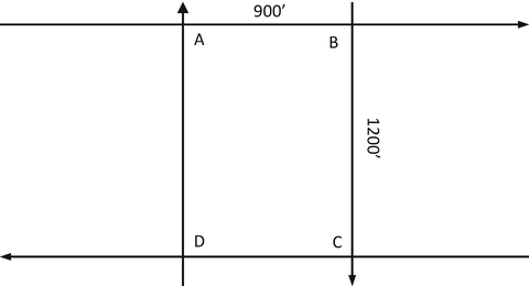
(Network coordinating) Given one block of a downtown street system as shown below, starting at intersection A, determine the start and end of green at all intersections in order to ensure that the signals will have network coordination. Begin with a design speed of 30 ft per second or 20 mph. Cycle time must be kept at 60 s. Assume a 50–50 split of green time. Do not use quarter-cycle offsets because they will produce speeds of progression in excess of 50 mph. Calculate your final speeds.
-
7.
(Network coordinating) The figure below shows a triangular network where signals are installed at each intersection and traffic flows as indicated. Block sizes and phase splits are indicated in the figure. Desired progression speed is 50 fps. Find a common cycle length and coordinate signals in this network.

-
8.
(Network coordinating on overlapping loops) The following problem concerns a network with overlapping loops. The desired speed is 50 fps or 34 mph. All intersections have a 50–50 phase splits. It is desired to have good progression about loop ABCFA and loop ABDEA. What cycle length will give that in the indicated directions?

-
9.
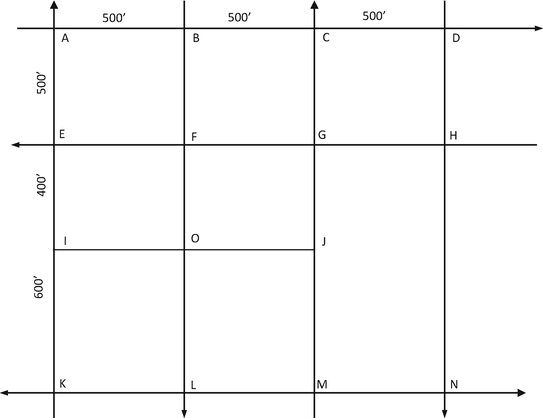
(Network coordinating on a complex network) In the network below, traffic flows in the directions indicated. The desired speed is 40 fps or 27.2 mph. All signals have 50–50 phase splits. Good progression is desired on loop ADHEA and loop ADNKA. Use intersection A as the reference signal. Note that link NK is on a double alternate system. Determine cycle length, final speeds, and start and end of green at coordinated intersections.


Rights and permissions
Copyright information
© 2020 Springer Nature Switzerland AG
About this chapter

Cite this chapter
Ni, D. (2020). Traffic Signal Coordination. In: Signalized Intersections. Springer, Cham. https://doi.org/10.1007/978-3-030-38549-1_14
Download citation
DOI: https://doi.org/10.1007/978-3-030-38549-1_14
Published:
Publisher Name: Springer, Cham
Print ISBN: 978-3-030-38548-4
Online ISBN: 978-3-030-38549-1
eBook Packages: EngineeringEngineering (R0)