
Abstract
Nowadays the interest in grid-supporting energy storage systems for frequency response improvement is spurred to increase the penetration of renewable energy resources. Operational frequency constraints of the grid code should be fulfilled in the combined state feedback frequency control provided through the BESS frequency support and UFLS relays. In this paper, favoritism and unfairness of the grid-interactive Battery Energy Storage System (BESS) frequency support is investigated in terms of Rate of Change of Frequency (RoCoF), frequency nadir, time response, steady-state error, and specifically, total load shed subject to power balance over the network. Categorizing load shedding stages into vital and non-vital can measure the appropriateness of the BESS response. Conflicts of the BESS control parameters, performance measures and UFLS actions are verified on the modified Cypriot transmission grid, and the simulation results show that a controller or modulation technique would be essential to coordinate the BESS and UFLS scheme frequency responses to handle conflict of controllers.
You have full access to this open access chapter, Download conference paper PDF
Keywords
- Battery Energy Storage System
- Under Frequency Load Shedding
- Dynamic frequency response
- Performance measures
1 Introduction
A rising interest to investigate the impact of high penetration of renewable generation on frequency control of power system and the capability of delivering frequency support by full Converter Control-Based Generators (CCBGs) is emerged during recent years [1]. Decrease of system inertia and conventional spinning reserve and increase of unpredictable uncertainties imposed by integrating renewables in the generation mix deteriorates the frequency support. By implementation of the virtual synchronous machine behavior [2, 3] through the new grid-supporting convertors of storages and renewables, the frequency support can be improved by means of the provided fast synthetic inertia and timely generation control in severe conditions [4].
In severe frequency decline situations, Under-Frequency Load Shedding (UFLS) programs (generally including event-based and response-based UFLSs) as the last automated measure of power system prevention from collapsing are designed and implemented by Transmission System Operator (TSO) through dynamic off-line simulations in operational planning time-scale. In response-based UFLS programs, the relay settings are usually pre-defined, fixed, and non-robust which may not be a comprehensive solution for the wide range of combinational/cascading events and operational variability and uncertainty imposed by high penetration of renewables [5]. Grid-interactive BESS can support the system operation during inertial and primary response through the inertia and droop parameters tuning of the SPC (Synchronous Power Controller).
Several TSOs have announced new grid codes requiring Electronically Interfaced Resources (EIRs) like energy storages, PVs, HVDC links, and wind power plants to provide frequency response [6]. The mutual interaction of UFLS as a traditional emergency control action has not been investigated enough under high share of renewable energy sources with BESS frequency support. The influence of the fast acting power controller of BESS on UFLS scheme and also mal-operation and readjustment of UFLS settings in high penetration of wind generation are presented in [7] and [8]. In [9], a systematic method is presented for controlling an energy storage system output power for preventing transient load shedding. Existing UFLS schemes suggested for conventional power systems has not been yet incorporated in grid-supporting convertors tuning to provide better inertial and primary frequency response.
A SPC-based Battery Energy Storage System (BESS) [10,11,12] as a linear state feedback controller could be tuned to control the performance of system frequency response measured by conflicting multi-dimensional performance measures such as minimum RoCoF and frequency, steady state error, and settling time. Good performance of UFLS schemes as another state feedback controller in conjunction with BESS frequency response is of great importance considering the fact that frequency support of the BESS may be harmful to some frequency performance measures or UFLS scheme performance. On the other hand, UFLS actions as a step change in RHS of the swing equation declines the BESS frequency response. Although, UFLS scheme has similar operation horizon as BESS frequency support, they used to be adjusted in different operational planning horizons, which makes the conflicts more complex and inevitable. In this paper, it is shown that the gains of the SPC and UFLS relays parameters need be adjusted in a coordinated manner to compromise between diverse technical and economic performance criteria of the frequency response.
The rest of the paper is constructed as follows: Sects. 2 and 3 provide an investigation of the impact of UFLS scheme and BESS inertia and droop characteristic on frequency response based on the unified discretized system frequency response using UFLS and BESS frequency responses formulation. Simulation results and discussion is presented in Sect. 4, respectively. The conclusion is drawn in Sect. 5.
2 Impact of BESS Inertia and Droop Characteristic on Frequency Response
2.1 Unified Discretized System Frequency Response
Based on the swing equation, accelerating and decelerating behaviour of the power system could be studied, when a power disturbance occurs. If the sum of all torques acting on the rotor shaft of a synchronous machine on the right-hand side of the swing equation including;
-
the mechanical torque (Tm) (power input),
-
the electrical torque (Te) (power output), and
-
the damping torque (Td) [Nm]
Does not add up to zero, the excess torque accelerates or decelerates the rotor with moment of inertia J [kg m2], meaning that the rotor angle θ [rad] accelerates (non-zero second derivative). By multiplying the swing equation with the system frequency ωb, the torques turn into power. In a single-area be made of Ng synchronous machine, the generalized continuous form of Center of Inertia (CoI) swing equation, presented in (1) is linearized as (2).
Terms of \( \Delta P^{im} \left( t \right) \) could be defined as a function of \( \frac{d\Delta f\left( t \right)}{dt} \) and/or \( \Delta f\left( t \right) \) or as a step input. Generation and load changes which may cause input power imbalance are: Generation outage \( (\Delta P^{c} ) \), Governor action \( (\Delta P^{gov} ) \), Wind, PV, and ESS frequency response \( (\Delta P^{wind} , \Delta P^{PV} \left( t \right),\Delta P^{ESS} \left( t \right) ) \) and load changes is incurred by load shedding \( (\Delta P^{sh} \left( t \right)) \), and load damping \( (D\Delta f\left( t \right)) \). By assuming each term of \( \Delta P^{im} \) as X, the system frequency response could be discretized over time with time step ∆t as \( \Delta X\left( {n\Delta t} \right) = \Delta X_{n} \).
The main focus of the rest of the paper is on the BESS influence on system frequency response and UFLS scheme. According to, other terms of (3) except than \( \Delta P^{ESS} \left( t \right) \) and \( \Delta P^{sh} \left( t \right) \) are ignored in the following equations. However, in simulation step, all of the resources contributing in the system frequency response are modelled and reflected.
2.2 System Acceleration Behaviour
The corresponding performance measures of the system frequency response are shown in Fig. 1.

Frequency performance measures illustration.
For a step-wise decrease in \( \Delta P^{c} \) from 0 to \( - \Delta P \) at the disturbance time t0, system frequency starts to drop fast with a high RoCoF. Higher RoCoF may activate the RoCoF relays of DGs and loads. The inertial and primary frequency response of the generations and loads try to limit the frequency deviation by increasing the system kinetic energy. At minimum frequency (Nadir frequency) time tm, RoCoF reaches zero and the frequency deviation \( \Delta f \) starts to decrease. Subsequently, \( \Delta f \) oscillates and finally stabilizes at the new steady-state frequency \( \Delta f_{ss} \).
Consequently, as shown in Fig. 2 the frequency response could be divided into areas in which the power system is accelerating, and others in which the system is decelerating. In an accelerating area, the frequency deviation \( \Delta f \) with respect to the steady-state frequency \( \Delta f_{ss} \) is increasing or in other words \( \Delta f - \Delta f_{ss} \) and RoCoF have the same sign. This can be written as:

Acceleration periods of power system frequency response.
2.3 BESS as a State Feedback Controller
The frequency response of storage can be similar to conventional units when participating in inertia and primary response. When the system is faced with large amount of power deficiency, ESS can provide FFR (Fast Frequency Response) based on the following transfer function [13]:
where \( H_{e} \) and \( R_{e} \) are inertia constant and primary frequency constant of control, respectively, and \( T_{e} \) is the time constant of BESS which is ignored in comparison to the time constants of the other and consistent with conventional units. Therefore;
Charging, discharging and power capacity limits of the BESS is assumed to be considered on the limits of the \( \Delta P^{ESS} \), \( H_{e} \) and \( R_{e} \). Integration of (8) in (3) results in (9).
In (9), BESS inertia and droop characteristics turn to be a state feedback on system frequency. In order to provide a better frequency response, we need to tune the inertia and damping of the BESS, which is achieved by regulating the converters’ SPC parameters (H and R) through a Multi-objective optimal gain-tuning method. A SPC-based BESS as a state feedback of the system DAEs is shown in Fig. 3 in which x is [\( f,\dot{f} \)] and K = [H, R] of the controller.

SPC-based BESS as a State feedback control.
2.4 Discussion on BESS Frequency Response
We may state that feedback can cause a system that is originally stable to become unstable. Certainly, feedback is a double-edged sword; when it is improperly used, it can be harmful [14]. Based on the (5) and (6), during accelerating time-intervals, to arrest the rate of change of frequency the system needs inertia emulated by the BESS. As soon as the system starts decelerating, inertia should reduce again to prevent overshoot in frequency response. The unused inertia imposes the frequency to return to the steady-state frequency slower, which deteriorates the overall frequency response.
Additionally, damping should be increased during decelerating phases to help decrease the settling time of the frequency deviation. The additional inertia required during accelerating phases is proportional to the RoCoF and the required additional damping is proportional to the frequency deviation from the steady state. Without adaptive damping and inertia control, the BESS response is not canceled out when the system has sufficiently stabilized which may result in unstable oscillations.
Due to the conflicting influence of the battery inertia and droop responses in accelerating and decelerating periods of frequency response, conflict of interests appears between different performance measures of frequency response with respect to the provided inertia and droop responses of BESS.
3 Response-Driven UFLS as a Non-linear State Feedback Controller
The response driven based load shedding, widely uses Under Frequency-based Load Shedding solutions. The inherent closed loop/ feedback based control scheme in decentralized response driven UFLS system makes them efficient in acting against the disturbances.
As frequency is a very good indicator of Power Mismatch, the operation based on under frequency relays has high control precision and robustness with respect to uncertainties. However, it can have many difficulties and challenges. The setting of the UFLS is highly complex, which involves many parameters including the number of LS stages, percentage of load allowed to be shed, the time delay for each stage, real time topology etc. Together these variables make the UFLS settings a non-linear and multi-dimensional problem. Secondly, UFLS is triggered after the frequency has already declined to certain low values causing a time delay, which makes the solution more reactive in nature and the system stability requires more time.
UFLS relays are characterized using incremented/decremented step behavior in swing equation. For simplicity, the related blocks can be represented as a sum of incremental (decremental) step functions. For instance, as presented in (10), for a fixed UFLS scheme [15], the function of \( \Delta P^{sh} \left( t \right) \) in the time domain could be considered as a sum of the incremental step functions of ∆Pk.u(t – tk). Therefore, for L load shedding steps:
(10) and (11) could be linearized using binary and big variables [16]. As stated above, the relay logic dictates that the block of load \( \Delta P_{k} \) be shed when the corresponding timer exceeds \( n_{k} \). When a contingency occurs, for each load-shedding stage k with \( f_{th}^{k} \), the relay disconnects a block of load after \( n_{k} \) time step when the frequency trajectory [computed using (3)–(4)] violates the frequency set point for a predetermined time delay.
3.1 Discussion on UFLS and BESS Mutual Effect
Similar to the SPC-based BESS frequency response, a response-driven based UFLS scheme is affecting the frequency response as a non-linear state feedback controller as presented in Fig. 4. f(x) is presented in (10).

SPC-based BESS and UFLS scheme as State feedback controls control.
UFLS action at \( t_{{f_{th} }} - t_{k} \) is a positive step change in generation-load imbalance which is reflected in system DAEs as a disturbance. Subsequent change in the rocof and frequency values alter the BESS inertial and primary response and reduce the BESS frequency support.
In some situations, however, frequency support of EIRs may be harmful to frequency control as they generate an extra energy in a short period of time, which reduces frequency decay and derivative but could not be maintained over time. Reduction of frequency derivative through emulating inertia via EIRs looks positive at first sight as the reduced frequency derivative triggers less under-frequency relays, but in some conditions, the shedded load is smaller than the amount what the event requires. As the EIRs cannot maintain extra generation over time, the frequency may continue to decay until the shedding of the next load step. It is also possible to activate other system and components protection by resulting in lower steady state frequency.
Based on (10) and (11), load shedding steps are activated, if the frequency reduces temporary or recurrently below a certain UFLS threshold. If the steady state frequency settles at a frequency above the same threshold, load shedding may be considered as nonvital. BESS can provide fast injection of power with limited energy capacity to prevent temporary frequency decreases and unnecessary load shedding. On the other hand, BESS should withdraw from support when the frequency decline is under arrest and additional load shedding would not be activated.
In order to avoid mal operation of UFLS scheme in the presence of the BESS frequency support, UFLS schemes should be incorporated in the controller tuning of the BESS as an economic objective to be optimized in conjunction with other frequency performance measures. In comparison with BESS controller tuning, most power systems operate with predetermined load shedding schemes and use fixed relay settings. Hence, resetting UFLS thresholds or changing load shedding amounts are not often viable options.
Moreover, with the existing supervisory and control capabilities, TSOs are not tendentious to re-design UFLS scheme for a short while. Then, the frequency thresholds, time delays and shed load percentage could be assumed fixed during the optimal gain-tuning of BESS. Using synchrophasor measurements for control of grid interactive energy storage system and UFLS relays [17] provide the possibility of coordinated online control of these resources of inertia and primary frequency response.
4 Studied System
4.1 System Modelling and Characteristics
There are 13 load shedding stages (~68% of the total load) spread over all Cyprus, which are presented in the following Table 1. This UFLS scheme is implemented in the system by definition and setting of the under frequency relays in DIgSILENT PowerFactory. A 50 MW, 100MWh BESS is added to the network equipped by SPC with tunable inertia and droop parameters of 15 and 60 as the maximum gains, as it is presented in [18]. The initial values of 0.5 and 0 are assumed for the SOC and power output states of the BESS, respectively. SOC limits are supposed as 0.2 and 0.8.
Other RHS terms of the swing equation in (2) are enclosed in the system modelling and control like turbine and governors, and Wind turbine standard controllers accorded to Grid Code requirements. Load damping effect are not considered in this study. The coincident disturbance of two generation units with 90 and 60 MW dispatch power is considered to tune the BESS parameters.
4.2 Conflict of Interests
In order to investigate the mutual effect of UFLS plan and BESS frequency support, system frequency response is presented in different scenarios in Fig. 5. As it is shown, without UFLS relays and BESS (a), with UFLS relays and without BESS (b), and with BESS (H = 5, R = 20) and UFLS (c) scenarios are studied.

Effect of UFLS plan and BESS frequency support on frequency response: red (b) and green (c).
Comparison of transient responses in these scenarios are summarized as follows:
-
1.
In (a), the system frequency decreases continuously until the system becomes unstable due to the cascading outage of conventional and renewable resources due to their under frequency relay activation. Primary and inertia support of conventional generation are not enough to arrest the frequency decline.
-
2.
By activation of UFLS in (b), the first three blocks of the UFLS plan are activated with 0.2 s delay after the frequency reaches the thresholds (taction = [2.89, 3.15, 3.95]). The non-vital shedding stage is avoided by BESS frequency support. Re-producing the frequency responses for three different combination of activated shedding stages in Fig. 6 (red: stage one, green: stage one and two, blue: all stages) analyses the necessity of the activated stage with respect to steady state frequency. While two first stages are categorized as vital, third stage is non-vital as the frequency settles above 48.8 without the activation of this stage.
Fig. 6. 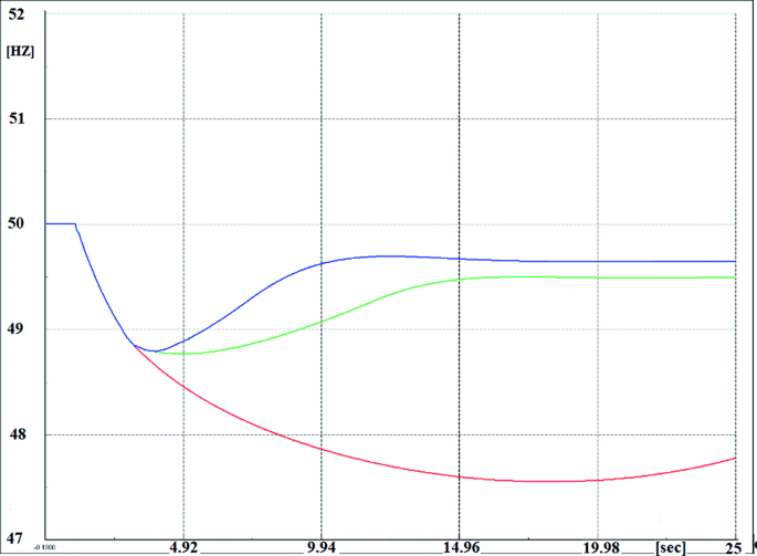
Vitality analysis of activated load shedding stages.
-
3.
Addition of BESS in (c), the first two blocks of the UFLS plan are activated with 0.2 s delay after the frequency reaches the thresholds (taction = [3.24, 3.74]). Although the non-vital shedding stage is avoided by BESS frequency support, other performance measures like RoCoF and minimum frequency are improved and response time and steady state frequency affected harmfully.

As it is presented in Table 2, a conflict of interests appears due to the parallel activation of UFLS and BESS frequency support in viewpoint of different performance measures. Undesirable effect of the BESS are grayed out in the table.
5 Conclusion
First, it was shown that by considering BESS droop and inertia gains along with the multistage UFLS plan, the overall performance of the load shedding plan and BESS frequency support are mutually influenced by each other in the both favorable and unfair directions. It was also revealed that the BESS droop and inertia gains are affecting frequency performance measures as a double-edged sword regarding system acceleration behaviour. Accordingly, the conflict of interests raised with respect to the UFLS and BESS state feedback controls interference (with similar operation and different planning horizons) should be handled through a gain tuning approach. Enabling coordinated online control of BESS parameters UFLS scheme using synchrophasor measurements provides better inertia and primary frequency response considering demonstrated conflicts of interest.
References
Dreidy, M., Mokhlis, H., Mekhilef, S.: Inertia response and frequency control techniques for renewable energy sources: a review. Renew. Sustain. Energy Rev. 69(November 2015), 144–155 (2017)
Rodriguez, P., Citro, C., Candela, J.I., Rocabert, J., Luna, A.: Flexible grid connection and islanding of SPC-based PV power converters. IEEE Trans. Ind. Appl. 54(3), 2690–2702 (2018)
D’Arco, S., Suul, J.A., Fosso, O.B.: A virtual synchronous machine implementation for distributed control of power converters in SmartGrids. Electr. Power Syst. Res. 122, 180–197 (2015)
Morren, J., de Haan, S.W.H., Kling, W.L., Ferreira, J.A.: Wind turbines emulating inertia and supporting primary frequency control. IEEE Trans. Power Syst. 21(1), 433–434 (2006)
Tang, L., McCalley, J.: Two-stage load control for severe under-frequency conditions. IEEE Trans. Power Syst. 31(3), 1943–1953 (2016)
Greenwood, D.M., Lim, K.Y., Patsios, C., Lyons, P.F., Lim, Y.S., Taylor, P.C.: Frequency response services designed for energy storage. Appl. Energy 203, 115–127 (2017)
Gonzalez-Longatt, F., Rueda, J., Vázquez Martínez, E.: Effect of fast acting power controller of battery energy storage systems in the under-frequency load shedding scheme. In: International Conference on Innovative Smart Grid Technologies (ISGT Asia 2018), no. June (2018)
Aparicio, N., Añó-Villalba, S., Belenguer, E., Blasco-Gimenez, R.: Automatic under-frequency load shedding mal-operation in power systems with high wind power penetration. Math. Comput. Simul. 146(2017), 200–209 (2018)
Pulendran, S., Tate, J.E.: Energy storage system control for prevention of transient under-frequency load shedding, pp. 1–11 (2015)
Zhang, W., Cantarellas, A.M., Rocabert, J., Luna, A., Rodriguez, P.: Synchronous power controller with flexible droop characteristics for renewable power generation systems. IEEE Trans. Sustain. Energy 7(4), 1572–1582 (2016)
Marin, L., Tarras, A., Candela, I., Rodriguez, P.: Stability analysis of a grid-connected VSC controlled by SPC
Eliassi, M., Paulino, P.A.B., Torkzadeh, R., Rodriguez, P.: Event-based under-frequency inertia emulation scheme for severe conditions
Khazaei, J., Nguyen, D.H., Thao, N.G.M.: Primary and secondary voltage/frequency controller design for energy storage devices using consensus theory. In: 2017 6th International Conference on Renewable Energy Research and Applications, ICRERA 2017, vol. 2017–Janua (2017)
Kuo, F.G.B.: Automatic Control Systems, pp. 398–401 (2002)
Hassan Bevrani, B., Verbic, G.S., Koepper, H.D.: Robust Power System Frequency Control, vol. 48, no. 2 (2009)
Banijamali, S., Amraee, T.: Semi adaptive setting of under frequency load shedding relays considering credible generation outage scenarios. IEEE Trans. Power Deliv. (2018)
Torkzadeh, R., Eliassi, M., Mazidi, P., Rodriguez, P.: Synchrophasor measurements for control of grid interactive energy storage system
Rocabert, J., Luna, A., Blaabjerg, F.: Control of power converters in AC microgrids. IEEE Trans. Power Electron. 27(11), 4734–4749 (2012)
Acknowledgments
This work was partially supported by the European Commission under project FLEXITRANSTORE—H2020-LCE-2016-2017-SGS-774407 and by the Spanish Ministry of Science under project ENE2017-88889-C2-1-R. Any opinions, findings and conclusions or recommendations expressed in this material are those of the authors and do not necessarily reflect those of the host institutions or funders.
Author information
Authors and Affiliations
Corresponding author
Editor information
Editors and Affiliations
Rights and permissions
Open Access This chapter is licensed under the terms of the Creative Commons Attribution 4.0 International License (http://creativecommons.org/licenses/by/4.0/), which permits use, sharing, adaptation, distribution and reproduction in any medium or format, as long as you give appropriate credit to the original author(s) and the source, provide a link to the Creative Commons license and indicate if changes were made.
The images or other third party material in this chapter are included in the chapter's Creative Commons license, unless indicated otherwise in a credit line to the material. If material is not included in the chapter's Creative Commons license and your intended use is not permitted by statutory regulation or exceeds the permitted use, you will need to obtain permission directly from the copyright holder.
Copyright information
© 2020 The Author(s)
About this paper

Cite this paper
Eliassi, M. et al. (2020). Conflict of Interests Between SPC-Based BESS and UFLS Scheme Frequency Responses. In: Németh, B., Ekonomou, L. (eds) Flexitranstore . ISH 2019. Lecture Notes in Electrical Engineering, vol 610. Springer, Cham. https://doi.org/10.1007/978-3-030-37818-9_6
Download citation
DOI: https://doi.org/10.1007/978-3-030-37818-9_6
Published:
Publisher Name: Springer, Cham
Print ISBN: 978-3-030-37817-2
Online ISBN: 978-3-030-37818-9
eBook Packages: EngineeringEngineering (R0)