
Abstract
The aim of tissue engineering is to create a working tissue for a replacement body part. Scaffold is the key biomedical device in tissue engineering applications, and in this chapter, we focus on scaffolds, including the key design parameters. In particular, a more detailed discussion on electrospinning is provided.
Access this chapter
Tax calculation will be finalised at checkout
Purchases are for personal use only
References and Further Reading
Blitterswijk, C.A., Boer, J.: Tissue Engineering. Academic Press, Cambridge, MA, USA (2015)
Schwab, M.: Encyclopedia of Cancer. Springer, New York (2008)
Brandrup, J., Immergut, E.H., Grulke, E.A., Abe, A., Bloch, D.R.: Polymer Handbook, vol. 7. Wiley, New York (1989)
Sperling, L.H.: Introduction to Physical Polymer Science. Wiley, Hoboken (2005)
Bosworth, L., Downes, S.: Electrospinning for Tissue Regeneration. Elsevier, Sawston, UK (2011)
Burdick, J.A., Mauck, R.L.: Biomaterials for Tissue Engineering Applications: A Review of the Past and Future Trends. Springer, New York, NY, USA (2010)
Basu, B., Katti, D.S., Kumar, A.: Advanced Biomaterials: Fundamentals, Processing, and Applications. Wiley, Hoboken (2010)
Bártolo, P., Bidanda, B.: Bio-Materials and Prototyping Applications in Medicine. Springer, New York (2008)
Subia, B., Kundu, J., Kundu, S.C.: Biomaterial Scaffold Fabrication Techniques for Potential Tissue Engineering Applications. IntechOpen (2010)
Minuth, W.W., Strehl, R., Schumacher, K.: Tissue Engineering: Essentials for Daily Laboratory Work. Wiley-VCH (2003)
O’Brien, F.: Biomaterials and scaffolds for tissue engineering. Mater. Today. 14, 88–95 (2011)
Hollister, S.J.: Porous Scaffold Design for Tissue Engineering. Nat. Mater. 4, 518–524 (2005)
Woodfield, T.B.F., Blitterswijk, C.V., Wijn, J.D., Sims, T.J., Hollander, A.P., Riesle, J.: Polymer scaffolds fabricated with pore-size gradients as a model for studying the zonal organization within tissue-engineered cartilage constructs. Tissue Eng. 11, 1297–1311 (2005)
Teixeira, S., Ferraz, M.P., Monteiro, F.J.: Biocompatibility of highly macroporous ceramic scaffolds: cell adhesion and morphology studies. J. Mater. Sci. Mater. Med. 19, 855–859 (2008)
Author information
Authors and Affiliations
Problems
Problems
1.1 Problem 11.1
Consider the configuration of electrospinning for a highly porous biomaterial as a scaffold for tissue engineering applications. A polyvinylpyrrolidone (PVP) monomer solution of 10 ml (VD) needs to be deposited on the substrate material. The solution has a viscosity of 10 × 10−3 kg/m s and a density of 1.2 g/cm3. This solution should flow through a needle with a length of 1.5 cm (L) and an inner radius (Rb) of 0.5 mm. The radius of the plunger (Rp), where the force for fluid motion is obtained through pressure exerted by the thumb, is 5 mm. A calibration experiment was performed previously for the relation between the flow rate and the average fiber diameter produced by electrospinning as shown in Fig. 11.P1.

Average fiber diameter against flow rate in the electrospinning process
In this question, we consider for manufacturing of a scaffold with a target fiber diameter of 800 nm.
-
(a)
What are the Reynolds number of the flow along (i) the cylinder and (ii) the needle?
-
(b)
What are the fluidic resistance (ΔP/Q) along (i) the cylinder and (ii) the needle?
-
(c)
Can you compare between the pressure drop in the cylinder and that in the needle?
-
(d)
What is the minimum required force applied to support the required rate of the liquid injection?
The polymerization process of PVP can be described as Fig. 11.P2 below:

Polymerization of poly(vinyl-pyrrolidone)
Consider also the molar weight of the PVP polymer (Mw) is 43,000 g/mole and the atomic weights of the atoms listed below (Table 11.P1).
-
(e)
What type of polymerization should this process be and why?
-
(f)
What is the degree of polymerization (DP)?
1.2 Problem 11.2
A sample for 3D printing of a scaffold is prepared by dissolving 0.10 g of polystyrene (molecular weight: 4.26 × 10⁶ g/mol) in 100 ml of butanone. The sample has a viscosity 1.273 times of the pure butanone. Given the empirical values of KP and ap in the Mark-Houwink-Staudinger relation have been previously obtained as 3.9 × 10⁻³ and 0.58, respectively, what is the sample viscosity?
1.3 Problem 11.3
The extension ratios (= λ) for four different molar masses (MP) of polyisobutylene in cyclohexane obtained at 30 °C are listed in Table 11.P2. Check that these data are consistent with Eq. 11.14.
1.4 Problem 11.4
Imagine that you are responsible for manufacturing an artificial bone for replacement of a bone fragment missing in the skull of a patient who had a serious injury in a car accident. A surgery was performed previously to remove a broken piece of bone. During the primary bone healing of the patient, your role is to manufacture a scaffold for the subsequent bone cell seeding and culture in order to develop the in vitro artificial bone. In the next surgery, this artificial bone will be placed at the missing location of the skull for sealing the skull.
-
(a)
Before the manufacturing, imaging of the skull should be performed to obtain the 3D geometry of the missing part of the bone. Can you suggest a bio-imaging method? Please describe briefly the working principle.
-
(b)
The scaffold was then fabricated by a rapid prototyping machine. The substrate material you could use is the composite of hydroxyapatite and PEG-PLA-PEG. Figure 11.P3 is showing the chemical synthesis of PEG-PLA-PEG. What kind of the polymerization is involved in this process? Please explain.
-
(c)
The composite should include mostly PEG-PLA-PEG, whose viscosity (μ) is ~8.872 × 10⁻³ kg/m·s. During the rapid prototyping process, the composite should be applied onto the sample for deposition using a syringe. The injection operation was controlled by a computer. The composite solution should flow through a syringe needle with a length of 0.1 mm (L) and an inner radius (Rb) of 0.1 mm. The radius of the plunger (Rp), where the force for fluid motion is obtained through pressure exerted by the thumb, is 1 cm. Assume that the solution flow rate is 5 nL/h. What is the minimum required force applied to support the required rate of the liquid injection?
-
(d)
The missing piece of bone had the shape as a quarter of a circular disc as shown below. Taking into account that a bone cell should have a diameter ~10 μm, the scaffold should have the separating hole/gap widths Dgap such that the cells can deposit and migrate inside the scaffold. Please design for scaffold and the corresponding path of the extruder/syringe needle for the fabrication.
Fig. 11.P4 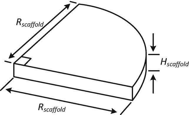
Geometry of a missing piece of bone
-
(e)
Please express the porosity of the scaffold as a function of Dgap.
-
(f)
Considering that the cured scaffold material has the Young’s modulus close to cure PLA (EPLA = 3.5 GPa), please express the equivalent compressive stiffness of the scaffold as a function of Dgap.
-
(g)
Based on the design and fabrication strategy you provided in part (d) and further considering the injection flow rate of the composite (as mentioned in part (c)) is now flexible (no longer fixed as 5 nL/h), denoted as Q, please estimate for the manufacturing time.
-
(h)
To achieve a functional scaffold, the allowable Dgap should be ≥30 μm such that cells can migrate into the inner scaffold body. The equivalent compressive stiffness Escaffold of the scaffold should be ≥0.5 GPa to maintain the structural shape after implantation. The patient’s injury site would need the scaffold dimensions of Rscaffold = 2 cm and Hscaffold = 3 mm. Furthermore, the flow rate Q can only be set ≤10 nL/h by the injection system. Given all these parameter settings/constraints, can you find out a set of feasible operation parameters and manufacturing time for your scaffold design? Please show how you obtain the results.


Polymerization of PEG-PLA-PEG
Rights and permissions
Copyright information
© 2019 Springer Nature Switzerland AG
About this chapter

Cite this chapter
Lam, R.H.W., Chen, W. (2019). Scaffold Design. In: Biomedical Devices. Springer, Cham. https://doi.org/10.1007/978-3-030-24237-4_11
Download citation
DOI: https://doi.org/10.1007/978-3-030-24237-4_11
Published:
Publisher Name: Springer, Cham
Print ISBN: 978-3-030-24236-7
Online ISBN: 978-3-030-24237-4
eBook Packages: Biomedical and Life SciencesBiomedical and Life Sciences (R0)