
Abstract
The above reference to lodestone is interesting in that it is over 2000 years old. The property of the magnetic field to attract or generate a force is universally known and is used in practical devices, probably more than most of us realize. How many applications of the permanent magnet do you recall? Did you know, for example, that many electric motors use permanent magnets or that the ignition in cars is commonly controlled by a permanent magnet and a Hall-element switch? It is therefore quite useful to identify the properties of the permanent magnet since sooner or later you will encounter it in design. Thus follows the study of magnetic properties of materials. Many materials exhibit magnetic properties, some quite surprising. The permanent magnet is only one of them. Iron, nickel, or chromium oxides on audio tapes, video tapes, or computer disks store information in the form of magnetic field variations. Solid nickel contracts when placed in a magnetic field, while strong magnetic fields cause atoms to tilt about their spin axes, a phenomenon that leads directly to magnetic resonance imaging (MRI). Naturally occurring materials, such as magnetite (Fe3O4), are found in bacteria and in brains of many animals which use this material as a biological compass for navigation in the geomagnetic field. Magnetite and hematite (Fe2O3) are the basis of the lodestone (a naturally occurring, magnetic stone).
Now sing my muse, fir ’tis a weighty cause.
Explain the Magnet, why it strongly draws,
And brings rough iron to its fond embrace.
This men admire; for they have often seen
Small rings of iron, six, or eight, or ten,
Compose a subtile chain, no tye between;
But, held by this, they seem to hang in air,
One to another sticks and wantons there;
So great the Loadstone’s force, so strong to bear!.
—Titus Lucretius Carus (94–50 BCE), De Rerum Natura (On the nature of things), T. Creech, Translation, London 1714.
Access this chapter
Tax calculation will be finalised at checkout
Purchases are for personal use only
Notes
- 1.
Caius Plinius Secundus. Pliny died during the eruption of Mount Vesuvius in 79 CE, the same eruption that buried Pompeii. In his book on Natural History, published around 77 CE, he mentions both the legend of discovery of the lodestone as well as an interesting story about magnetic suspension. He goes on to describe the various types of lodestone found at the time and locations where these are found. One particularly interesting is the haematite (blood-stone, from its red color). This is essentially rust: Fe2O3 which is only very slightly magnetic. The common lodestone is made of magnetite (Fe3O4 and tends to be black). His description of the stone as the most marvelous thing there is or “lifelike” is poetic, but many attributes such as curative powers are totally absurd. According to Pliny, other common names for the stone were “live iron,” “Heraclion” (a reference to either the city of Heraclea or Hercules, referring to its power over iron), and “Sideratis” (iron earth).
- 2.
Thales of Miletus is believed to be the earliest to mention the lodestone, although he probably learned of it during his travels in Egypt (see footnote 2 on page 98). Thales is said to have believed (according to Aristotle) that the magnet has soul since it attracted (had “sympathy” to) iron.
- 3.
Pliny writes that an architect by the name of Timochares by order from King Ptolemy II, Phyladelphus, began to put a vaulted roof of lodestone on the temple of Arsinoe (Ptolemy’s wife) in Alexandria, so that her statue, made of iron, would be suspended in air. Another mention by Ruffinus says that in the temple of Serapis (in Memphis, Egypt), there was an iron chariot suspended by lodestones. When the stones were removed, the chariot fell and was smashed to pieces. Beda (the Venerable) says that a statue of Bellerophon’s horse (Pegasus) framed of iron was placed between lodestones, with wings expanded, floating in air. These are legends, but that the idea of suspending iron by lodestone was mentioned almost 2000 years ago is remarkable in itself. Magnetic levitation seems to be not all that new, at least not in concept.
- 4.
William Gilbert (1540–1603) is most often mentioned as physician to Queen Elisabeth I (even though this occurred only during the last 2 years of his life), but his education included Mathematics and Physics. His main activity prior to the publication of De Magnete was in medicine, but he also experimented in chemistry and, certainly, in magnetics. His book became to be appreciated as one of the first to describe systematic experiment without regard to mysticism, opinions, and perpetuation of unfounded information and was the culmination of 18 years of careful (and expensive) experimental work. It is fascinating to read how he disclaims opinions of ancients and contemporaries about magnetic properties attributed to planets or constellations or that rubbing of a magnet with garlic will cause it to lose its properties. These seemingly trivial experiments were necessary to dispute prevalent notions of the time, including that magnet will not attract iron in the presence of diamonds or that it will lose its attraction if rubbed by onions, garlic, or goat’s blood. For example, in Book III, Chapter XIII, he describes an experimant in which he surrounded a lodestone by 75 “excellent” diamonds in the presence of witnesses and could observe no effect on the magnetic field or that rubbing a magnetic needle with a diamond does not affect it (one belief held was that the diamond will cause the needle to reverse its action). Gilbert died in the plague of 1603.
- 5.
The magnetic compass is believed to have been invented in China and perhaps later, separately, in Europe. There are also some stories about Marco Polo having brought it from China, but this cannot be true, as mention of the compass as a known instrument in Europe can be traced as far back as 1180 CE. Compasses were known to be made in Italy before 1300 CE (at Amalfi, near Naples) whereas Marco Polo returned from China in 1295. According to some accounts, the compass was known in China as early as 1100 BCE. One account gives details of a chariot, on which a figurine with outstretched arms points to the south. The figurine was pivoted and had in it lodestones to act as a compass. The time: 2637 BCE in China.
- 6.
After Joseph Henry (1797–1878), Professor of Mathematics and Natural Philosophy at Albany and later at Princeton. His major contributions to electricity and magnetism are the development of the electromagnet and the study of induced currents. He was the first to show the potential uses of the magnetic force. When he developed his powerful electromagnets (the Smithsonian Institution still has one of his early electromagnets, capable of lifting up to 1.5 tons), it became evident that magnetism was of practical importance and led directly to the development of electric motors and other electromagnetic power devices. These investigations were made in parallel to those of Michael Faraday. Henry became the first secretary of the Smithsonian Institution in 1846 and served in this capacity until his death. Others of his interests led to the demonstration of telegraphy, a primitive form of which he used to communicate between his office and home. He was an enthusiastic meteorologist and is credited with influencing the establishment of the U.S. Weather Bureau.
- 7.
Pierre Weiss (1865–1940), French physicist and perhaps the first to initiate the study of atomic level magnetic fields, theorized in 1907 that coupling forces in domains must exist, and these forces hold the spins together. The existence of domains as well as loss of magnetization beyond a certain temperature (Curie point) were also part of Weiss’ work. The domain walls are sometimes called Weiss walls or Bloch walls (after Felix Bloch, Swiss physicist and recipient of the 1952 Nobel Prize in Physics).
- 8.
This force is called the Laplace force although we derived it from the Lorentz force. The distinction between the two forces is in the fact that the Laplace force is a macroscopic force on the ensemble of moving charges whereas the Lorentz force is the microscopic force on a moving charged particle.
Author information
Authors and Affiliations
Corresponding author
Problems
Problems
9.1.1 Magnetic Dipoles and Magnetization
-
9.1
Application: Magnetic Dipole. A small circular loop of radius a [m] and a small, square loop, a × a [m2] are given.
-
(a)
Calculate the magnetic dipole moment of the circular loop.
-
(b)
Justify based on physical considerations the following statement: “At large distances, the magnetic dipole of the square loop is the same as that of a circular loop of identical area.”
-
(c)
Calculate the magnetic flux density at a general point in space due to each loop for the conditions in (b).
-
(a)
-
9.2
Magnetic Dipole. A loop of radius a [m] carries a current I [A]. A second, smaller loop of radius b [m] is placed at point P1 (on the axis of the first loop, at height h [m] above the loop), at point P2 (at a horizontal distance h [m], on the plane of the first loop) or at point P3 so that the planes of the two loops are parallel in all three cases (Figure 9.57). In all three cases, h ≫ b, a > b and h ≫ a. Calculate the total flux through the small loop produced by the large loop (in free space) when:
-
(a)
The small loop is at point P1.
-
(b)
The small loop is at point P2.
-
(c)
The small loop is at point P3.
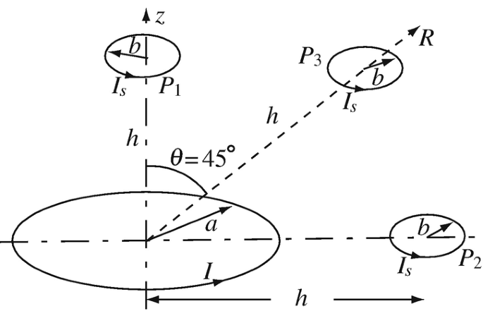
Figure 9.57
-
(a)
-
9.3
Magnetization. A very long cylindrical magnet has constant magnetization M [A/m], directed as in Figure 9.58. A solenoid made of thin wires is wound tightly around the magnet, with n turns per unit length of the solenoid. What must be the current (magnitude and direction) in the coil to cancel the magnetization of the magnet?
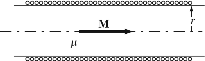
Figure 9.58
-
9.4
Application: Magnetization and Magnetic Field in a Permanent Magnet. A very long cylindrical magnet has magnetization M [A/m] as shown in Figure 9.58. The magnet is made of a material with permittivity μ [H/m]. Calculate the magnetic field intensity inside the magnet. Disregard the solenoid shown.


9.1.2 Magnetic Interface Conditions
-
9.5
Magnetic Interface Conditions. A magnetic field intensity H [A/m] is given at the interface between materials (1) and (2) as shown in Figure 9.59. Calculate the direction and magnitude of the magnetic flux density in materials (2) and (3). Assume there are no surface currents on the interfaces.
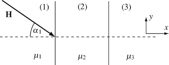
Figure 9.59
-
9.6
Interface Conditions for Ferromagnetic Media. The relative permeability of a large, flat piece of iron is 100. If the magnetic field intensity in the iron must be at 60° to the surface, what must be the direction of the magnetic field intensity at the surface of the iron piece in air? Assume there are no currents on the interfaces.
-
9.7
Interface Conditions and Flux Density. A two-layer magnetic sheet is made as shown in Figure 9.60. Each sheet is d [m] thick. Permeabilities are μ1 = μ0, μ2 = 200μ0, μ3 = 50μ0, and μ4 = μ0 [H/m]. A magnetic flux density in material (1) is given at 30° to the normal and of magnitude B = 0.01 T. Calculate the magnetic flux density (magnitude and direction) in materials (2), (3) and (4).
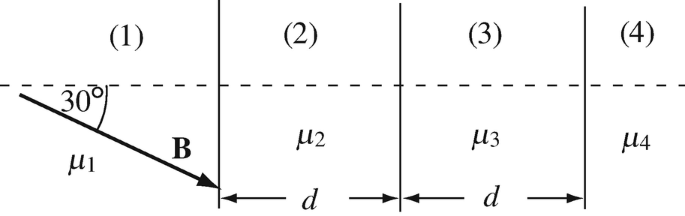
Figure 9.60


9.1.3 Inductance
-
9.8
Application: Self- and Mutual Inductances of Coils. A coil is wound uniformly in the form of a torus (see Figure 9.61). A long solenoid, of radius a < b [m] and n turns per unit length, is inserted in the central hole of the torus as shown. Calculate:
-
(a)
The self-inductance of the toroidal coil.
-
(b)
The self-inductance per unit length of the solenoid.
-
(c)
The mutual inductance between the toroidal coil and the solenoid.
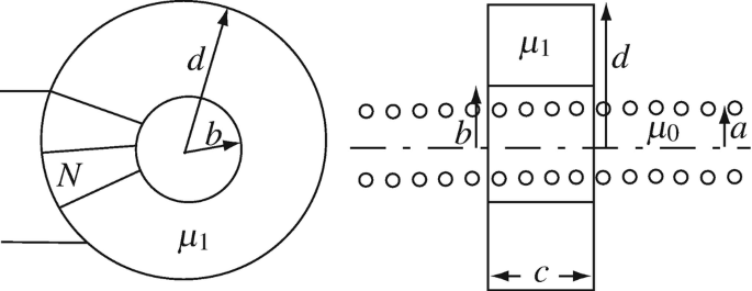
Figure 9.61
-
(a)
-
9.9
Application: Self- and Mutual Inductances of Coils. Three coils are wound on two toroidal cores as follows: Coil 1 is wound uniformly with N1 turns on one of the cores. This is shown in two views in Figure 9.62a including the dimensions of the core. Coil 2 is wound uniformly with N2 turns on a second identical core. Now both cores are placed side by side as shown in Figure 9.62b. Coil 3 is wound uniformly with N3 turns on the two cores (on top of coils 1 and 2) as shown in Figure 9.62b in cross-section. The permeability of the cores is μ [H/m]. Calculate:
-
(a)
The self inductance of each of the coils
-
(b)
The mutual inductances between each pair of coils
-
(c)
The total inductance of each of the coils if the fluxes produced by the three coils are in the same direction.
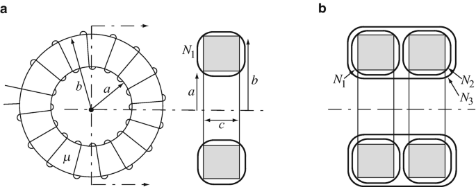
Figure 9.62
-
(a)
-
9.10
Application: Self-inductance of Long Solenoid. A long solenoid is wound on a hollow cylinder made of iron. Dimensions are given in Figure 9.63. Permeability of iron is μ1 > μ0 and that of free space is μ0 [H/m]. The solenoid carries a current I [A] and has n turns per unit length. Calculate the self-inductance per unit length of the solenoid.
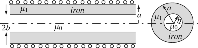
Figure 9.63
-
9.11
Inductance of a Double Cylinder. A thin sheet of copper is bent into an infinitely long double cylinder as shown in cross section and three-dimensional view in Figure 9.64. Calculate the inductance per unit length of the double cylinder. For purposes of calculation, assume d → 0.
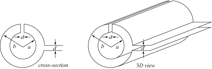
Figure 9.64
-
9.12
Mutual Inductance Between Straight Wire and Loop. A straight, long wire is placed in a plane in free space. A rectangular loop is also in the same plane as shown in Figure 9.65a.
-
(a)
Calculate the mutual inductance between wire and loop.
-
(b)
Now the wire is moved so that it is above the center of the loop without actually touching it as shown in Figure 9.65b. What is now the mutual inductance between wire and loop?
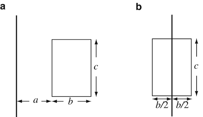
Figure 9.65
-
(a)
-
9.13
Mutual Inductance Between Wire and Solenoid. A very long wire (infinite for practical purposes) is located at a distance d [m] from the center of an infinite solenoid in free space (Figure 9.66). The solenoid has a radius b [m] (b < d) and n turns per unit length. The solenoid and the wire are at 90° to each other, as shown. Calculate the mutual inductance between solenoid and wire.
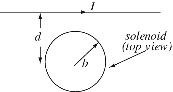
Figure 9.66
-
9.14
Mutual Inductance Between Coil and Solenoid. A very long (infinite) solenoid with N turns per unit length and radius a [m] is given. A coil with two turns and radius b [m] (b > a) is located (in free space) as shown in Figure 9.67. The coil and solenoid do not touch.
-
(a)
Calculate the mutual inductance between the coil and solenoid.
-
(b)
Suppose the coil is now rotated so that it makes a 45° angle with the axis of the solenoid. What is now the mutual inductance between the coil and solenoid? (The solenoid is entirely enclosed within the coil.)
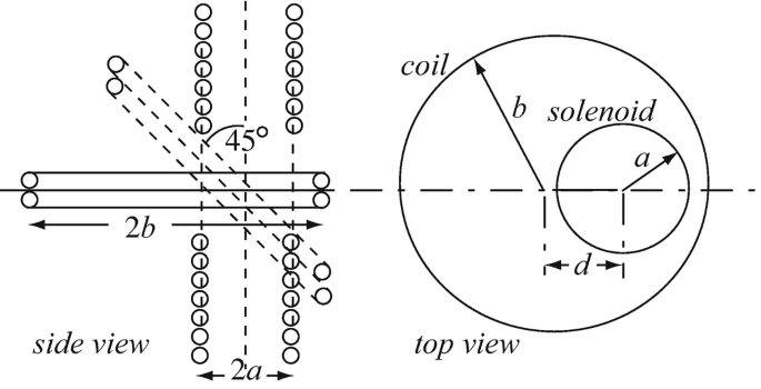
Figure 9.67
-
(a)
-
9.15
Application: Mutual Inductance Between Loops. The geometry and conditions in Problem 9.2 are given. Calculate the mutual inductances Lab and Lba between the large loop and the small loop if:
-
(a)
The small loop is at point P1 in Figure 9.57 and parallel to the large loop. Write the necessary assumptions.
-
(b)
The small loop is at point P2 in Figure 9.57 and parallel to the large loop. Write the necessary assumptions.
-
(c)
T small loop is at point P3 in Figure 9.57 and parallel to the large loop. Write the necessary assumptions.
-
(d)
Based on the calculation in (a) through (c), does the relation Lab = Lba hold? Explain.
-
(a)
-
9.16
Application: Inductors in Series and Parallel. Three inductors, each of inductance L [H] are connected as shown in Figure 9.68. Assume first that the inductors experience no mutual inductance.
-
(a)
Calculate the total inductance for the series connection in Figure 9.68a.
-
(b)
Calculate the total inductance for the parallel connection in Figure 9.68b.
-
(c)
Calculate the total inductance for the connection in Figure 9.68c.
-
(d)
Repeat (a) through (c) if between each two inductors there is a mutual inductance equal to M [H]. Assume the fluxes in all three coils are in the same direction.
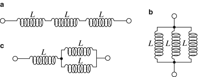
Figure 9.68
-
(a)
-
9.17
Application: Inductance per Unit Length of Coaxial Cables. A coaxial cable is made of an inner cylindrical shell of radius b [m] and an outer, concentric cylindrical shell of radius a [m], separated by a dielectric with permeability μ0 [H/m]. Calculate the inductance per unit length of the coaxial cable. Assume the shells are very thin.
-
9.18
Application: Internal and External Inductances. A coaxial cable is made of a solid inner conductor of radius b [m] and a concentric, outer solid conductor of inner radius a [m] and outer radius c [m]. The conductors are separated by a material of permeability μ0 [H/m]. Assume any current in the conductors is uniformly distributed throughout the conductor’s cross-sectional area and the permeability of the conductors is μ0 [H/m]. Calculate:
-
(a)
The internal inductance per unit length due to the inner conductor.
-
(b)
The internal inductance per unit length due to the outer conductor.
-
(c)
The external inductance per unit length of the cable.
-
(d)
The total inductance per unit length of the cable.
-
(a)
-
9.19
Application: Inductance Per Unit Length of Cables. Two two-wire cables carry a current I1 [A] and I2 [A] as shown in Figure 9.69. Both cables can be assumed to be very long (infinite) and both are placed flat on a plane in free space. Calculate:
-
(a)
The external self-inductance per unit length of each cable.
-
(b)
The mutual inductance per unit length between the two cables.
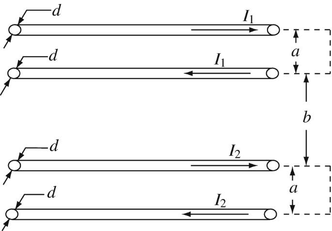
Figure 9.69
-
(a)
-
9.20
Application: Self- and Mutual Inductance in Printed Circuit Boards. The configuration shown in Figure 9.70 represents part of a printed circuit board (PCB). The two outer conductors represent the power supply traces and may be assumed to be long, whereas the loop in the center is part of the functional circuit and is small. The outer traces are of width 2t. The permeability of the PCB is μ0 [H/m] and the dimensions are as follows: a = 25 mm, b = 20 mm, c = 4 mm, d = 6 mm, and t = 1 mm. Calculate:
-
(a)
The external self-inductance per unit length of the outer circuit.
-
(b)
The total self-inductance per unit length of the outer circuit.
-
(c)
The mutual inductance between the loop and the outer circuit. Neglect the thickness of the traces of the small loop for the purpose of this calculation.
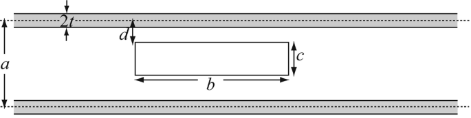
Figure 9.70
-
(a)


9.1.4 Energy
-
9.21
Stored Energy in a System of Inductors. An infinite solenoid with n1 turns per unit length and radius a [m] carries a current I [A]. A second infinite solenoid, with n2 turns per unit length and radius b [m], is placed over the first as shown in Figure 9.71a. The two solenoids do not actually touch. Figure 9.71b shows the relation of the two solenoids from an axial view. The second solenoid also carries a current I [A]. Calculate the change in energy per unit length in the system (made of the two solenoids) when:
-
(a)
The current in the inner solenoid is reversed.
-
(b)
The current in the outer solenoid is switched off.
-
(c)
The current in the inner solenoid is switched off.
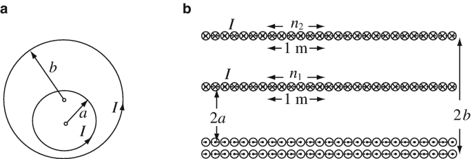
Figure 9.71
-
(a)
-
9.22
Change in Stored Energy Due to Change in Material properties. A toroidal coil of inner radius r1 [m], outer radius r2 [m], and square cross section is shown in Figure 9.72. The material of the torus has permeability μ1 > μ0, the coil has N turns and carries a current I [A]. Calculate the change in the stored magnetic energy if the material inside the torus is removed (the core of the torus is in effect replaced with free space).
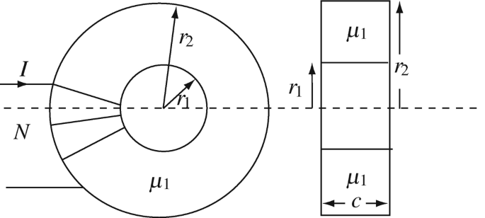
Figure 9.72
-
9.23
Stored Energy in a Gap. A toroidal coil of inner radius r1 [m], outer radius r2 [m], and square cross section is given as shown in Figure 9.72. The material of the torus has permeability μ1 > μ0, the coil has N turns and carries a current I [A]. Calculate the change in the stored magnetic energy if a gap of length lg [m] is cut in the torus. Assume the gap does not create flux leakage and the average radius is (r2 + r1)/2 [m].
-
9.24
Stored Energy in Series-Connected Inductors. Consider the torus and configuration given in Figure 9.25. For the given values and with N3 = 2N2 = 2N1 turns calculate:
-
(a)
The total energy stored in the torus, if all three fluxes produced by the coils are in the same direction.
-
(b)
Now, all three coils are connected in series to a current I [A] (I1 = I2 = I3 = I). It is required that the torus store the minimum possible energy. Show how the coils must be connected and calculate the energy stored and the equivalent inductance under this condition.
-
(c)
The configuration now is as in (b), but it is required that the torus store maximum energy. Show how the connections must be made to accomplish this and calculate the stored energy and the equivalent inductance.
-
(a)
-
9.25
Application: Energy Stored in a Magnet. A cylindrical permanent magnet of radius a [m] with constant magnetization \( \mathbf{M}=\hat{\mathbf{z}}{M}_0 \) [A/m] and infinite in length is given. Calculate the energy stored per unit volume of the magnet. Assume permeability of the magnet is μ0 [H/m].
-
9.26
Work Necessary to Modify a Magnetic Core. A long (infinite) solenoid of radius a [m] has n turns per unit length. The turns carry a current I [A]. An equally long piece of iron also of radius a [m] is placed in the solenoid, as shown in Figure 9.73. The relative permeability of iron is μr and that of free space is 1. Calculate the total work per unit length of the solenoid necessary to pull the iron completely out of the solenoid. Does this work increase or decrease the potential energy of the system? Explain.
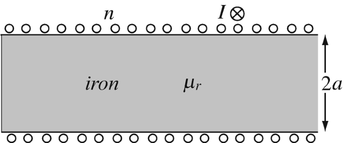
Figure 9.73
-
9.27
Change in Energy Due to Change in Mutual Inductance. A square loop b [m] by b [m] is located outside a very long solenoid with a total of N turns. Both the solenoid and the loop carry a current I [A] as shown in Figure 9.74a. Assume that the solenoid is d [m] long but that its field is identical to an infinite solenoid of the same radius and that there is no mutual inductance between loop and solenoid in Figure 9.74a. Assume free space.
-
(a)
Calculate the change in energy in the system if the loop is placed inside the solenoid (\( b<a\sqrt{2} \)) while the loop is perpendicular to the axis of the solenoid (Figure 9.74b).
-
(b)
Calculate the change in energy in the system if the loop is placed over the solenoid (b > a) while the loop is perpendicular to the axis of the solenoid (Figure 9.74c).
-
(c)
What are the answers to (a) and (b) if the current in the square loop is reversed?
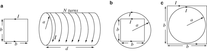
Figure 9.74
-
(a)


9.1.5 Magnetic Circuits
-
9.28
Application: Flux in a Toroidal Magnetic Circuit. A straight, long wire passes at the center of a torus as shown in Figure 9.75 and carries a current I [A]. The torus has permeability μ [H/m].
-
(a)
Calculate the total flux in the torus due to the current in the wire.
-
(b)
What is the flux if a gap of length lg [m] is cut in the torus (dotted lines)? Assume (d – b ) ≫ b.
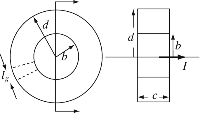
Figure 9.75
-
(a)
-
9.29
Application: Magnetic Circuits. Calculation of Flux and Field Intensity. A magnetic circuit is given in Figure 9.76. The magnetic circuit has two gaps as shown. A single turn of wire carrying a current I [A] is placed in the center of one of the gaps. The loop is b by c in dimensions. Assume e > b, that all flux is contained within the magnetic circuit and that the magnetic path length is the average length of the corresponding section. Use the following: a = 10 cm, b = 1 cm, c = 2 cm, d = 5 cm, e = 4 cm, g = 0.1 cm μ1 = 200μ0 [H/m], I = 0.4 A. Calculate:
-
(a)
The flux in gap (2) if the loop is placed in gap (1).
-
(b)
The minimum and maximum magnetic field intensity (H) in the circuit if the loop is placed in gap (1). Where do these occur?
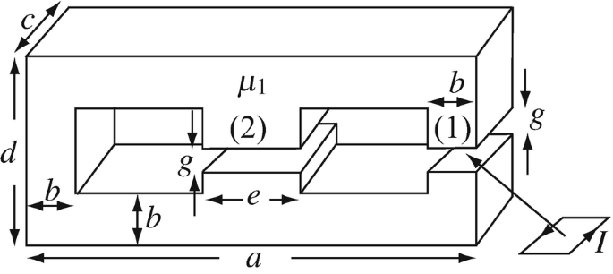
Figure 9.76
-
(a)
-
9.30
Application: Mutual Inductance in a Magnetic Circuit. A torus with average radius r0 [m] and cross-sectional area as shown in Figure 9.77 is given. A coil with N turns is wound around the torus. A small gap of length lg [m] is cut in the torus and a loop of radius a [m] is inserted in the gap, such that the loop is centered in the gap. Calculate the mutual inductance between the loop and the coil. Assume r0 ≫ b, a < b.
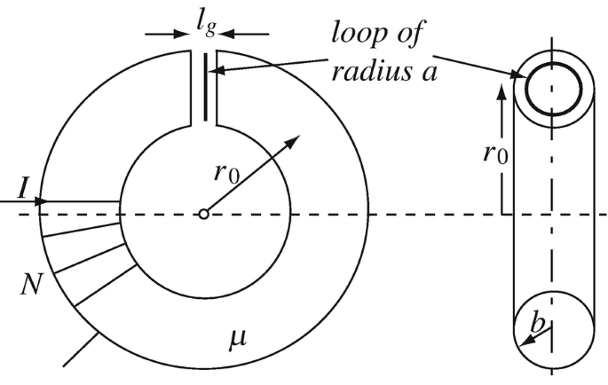
Figure 9.77
-
9.31
Magnetic Circuit with Different Materials. The magnetic circuit in Figure 9.78 is given. The two halves are made of different materials with different permeabilities. The length of the gap is lg [m]. The cross-sectional area of the core is the same everywhere. Calculate the magnetic field intensity in the gap. Assume a ≫ lg and d ≫ lg.
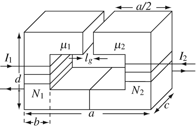
Figure 9.78
-
9.32
Magnetic Circuit with Different Materials. A torus is made of two types of materials with four small gaps as shown in Figure 9.79. Assume the gaps have properties of free space. The coil has N turns, uniformly wound around the torus and carries a current I [A]. Calculate the flux density in the gaps assuming there is no flux leakage at the edges of the gaps.
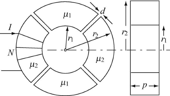
Figure 9.79
-
9.33
Application: Stored Energy and Magnetic Flux Density in a Magnetic Circuit. The magnetic circuit in Figure 9.80 is given. The two halves are made of different materials with different permeabilities. The length of each gap is lg [m]. The cross-sectional area of the core is constant. Take the magnetic path as the average length of the core:
-
(a)
If I1 and I2 are known, calculate the total energy stored in the magnetic field.
-
(b)
If I1 is known, calculate I2 such that the magnetic field intensity in the gap is zero. Show its direction.
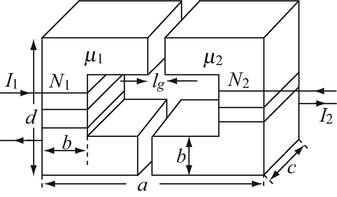
Figure 9.80
-
(a)
-
9.34
Stored Energy in a Magnetic Device. The core shown in Figure 9.81 is made of two pieces. Two gaps exist between the two pieces as shown. The cross-sectional area of the two pieces is the same and is constant. The relative permeability of the upper and lower piece tends to infinity. Currents, number of turns, and dimensions are as shown. Calculate the total magnetic energy stored in the magnetic field of this device.
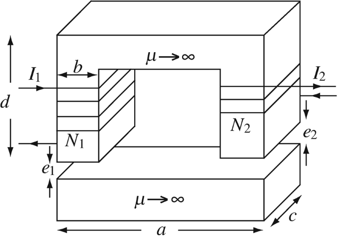
Figure 9.81
-
9.35
Mutual Inductance. An iron core is made as shown in Figure 9.82. A coil (L1) with N1 turns is wound on the right leg of the core and a coil (L2) with N2 turns is wound on the left leg of the core. Calculate the mutual inductance between the two coils.
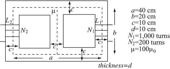
Figure 9.82


9.1.6 Forces
-
9.36
Application: Force on a Current-Carrying Conductor. A thin bar 1 m long carries a current I = 10 A. What is the maximum force that the terrestrial magnetic field exerts on the bar? Assume the magnetic field of the planet is parallel to the surface of the earth and equal to B = 50 μT. Show the required orientation of the bar so that the force is maximum.
-
9.37
Application: Force on a Loop. A current I1 [A] flows in a thin conducting wire in the positive z direction. A rectangular loop carries a current I2 [A] as shown in Figure 9.83a. Dimensions are as shown and the loop and wire are on a plane. In Figure 9.83b assume the wire and loop are on a plane but do not touch. Assuming free space, find:
-
(a)
The force on the loop in Figure 9.83a (magnitude and direction).
-
(b)
The force on the wire in Figure 9.83a (magnitude and direction).
-
(c)
The force on the wire as a function of the distance a in Figure 9.83b for 0 < a < b.
-
(d)
What is the force in (c) if a = b/2?
-
(e)
What is the force if a → 0?
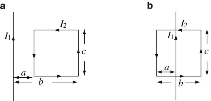
Figure 9.83
-
(a)
-
9.38
Forces Between Current-Carrying Conductors. A very long, thin wire passes between two rectangular loops as shown in Figure 9.84. The wire carries a current I0 = 3 A, loop (1) carries a current I1 = 4 A, and loop (2) carries a current I2 = 2 A, in the directions shown in Figure 9.84. The loops and the wire are on the y–z plane with the loops symmetric about the y-axis.
-
(a)
Calculate the force on each loop due to the current in the wire.
-
(b)
Calculate the total force on the wire due to the currents in the two loops.
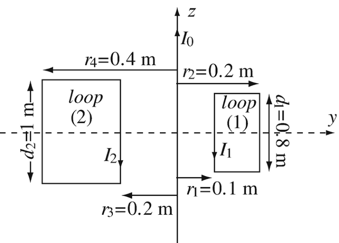
Figure 9.84
-
(a)
-
9.39
Forces on Thick, Current-Carrying Conductors. Two infinitely long conducting bars (shown in cross section in Figure 9.85) carry a current I [A] as shown.
-
(a)
Write an expression for the force per unit length between the two conductors (do not evaluate the integrals).
-
(b)
Is this an attraction or repulsion force? Explain.
-
(c)
Optional: Integrate the expression in (a) for a = 0.05 m, b = 0.2 m, d = 0.2 m, c = 0.1 m, I = 1,000 A, and μ = μ0 [H/m] everywhere.
Note: The integral is very tedious. You may want to write a script or computer program to accomplish the integration.
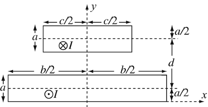
Figure 9.85
-
(a)
-
9.40
Force Between Loops. Two square loops in free space are parallel to each other and carry currents as shown in Figure 9.86.
-
(a)
Show, without calculations, that the two loops attract each other.
-
(b)
Write the expression for the total force on one of the loops.
-
(c)
Optional: Evaluate the force in (b) for a = d = 1 m, b = 2 m, and I1 = I2 = 1 A.
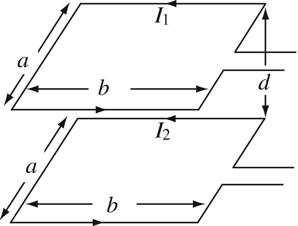
Figure 9.86
-
(a)
-
9.41
Application: Forces in a Magnetic Circuit. A lifting electromagnet designed to lift steel bars is built as shown in Figure 9.87. To protect the poles, they are coated with a thin polymer of thickness t so that the minimum gap between the magnet and the bar being lifted equals t. Assuming the permeability of both the electromagnet core and the steel bar equal 200μ0 [H/m], calculate:
-
(a)
The weight per unit current in the coil that the device can hold.
-
(b)
What is the current needed to hold a 1 ton bar.
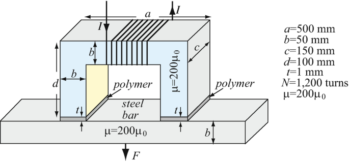
Figure 9.87
-
(a)
-
9.42
Application: Forces on Magnetic Poles of a Gap. In Figure 9.88, calculate the force that exists between the two faces of the gap. The magnetic path has a permeability equal to μ [H/m] and the core is d [m] thick. a, b, and g are the average path lengths of the corresponding magnetic path sections.
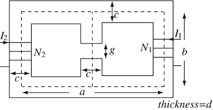
Figure 9.88


9.1.7 Torque
-
9.43
Application: Torque on a Current-Carrying Loop. Calculate:
-
9.44
Torque on a Current-Carrying Bar. A thin bar of length a = 1 m carries a current I and is placed in a uniform magnetic field. The magnetic flux density is \( \hat{\mathbf{B}}=\hat{\mathbf{z}}{B}_0 \) where B0 = 0.4 T and the current in the bar is 0.1 A. The bar is pivoted at its center and connected to the current as shown in Figure 9.89a.
-
(a)
Calculate the torque on the bar. Show the direction of forces.
-
(b)
Suppose the source is connected as in Figure 9.89b. What is now the torque on the bar?
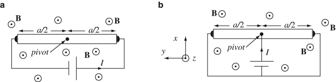
Figure 9.89
-
(a)
-
9.45
Application: Torque on Magnetic Dipoles. A loop of radius a [m] carries a current I [A]. A second, small loop of radius b [m] carries a current Is [A] and is placed at point P1, P2, or P3 as shown in Figure 9.57. In all cases, h ≫ b, a ≫ b, h ≫ a, and the axes of the loops are parallel to each other. Calculate the torque:
-
(a)
On the small loop when the small loop is at point P1.
-
(b)
On the small loop when the small loop is at point P2.
-
(c)
On the small loop when the small loop is at point P3.
-
(d)
On the large loop for the configuration in (c).
-
(a)
-
9.46
Torque on Small Loops. A small circular loop of radius a [m] is placed flat on a surface. A second, square loop, a × a [m2], is placed on the same surface at a distance d [m] such that d ≫ a (Figure 9.90a). The circular loop carries a current Ic [A] and the square loop a current Is [A], both are in free space.
-
(a)
Find the magnetic dipole moments of the circular and square loops in Figure 9.90a.
-
(b)
Now, the square loop is rotated around its axis as in Figure 9.90b so that the side de is up without changing the directions of the currents. Calculate the torque on the round loop.
-
(c)
Assuming the conditions in (b), the number of turns in the round loop is increased to N. How does this affect the torque on the square loop?
-
(d)
Assuming the conditions in (c), the current in the round loop is changed to flow in the direction opposite that shown in Figure 9.90b and the number of turns in the square loop is also increased to N. Calculate the torque on the round loop.
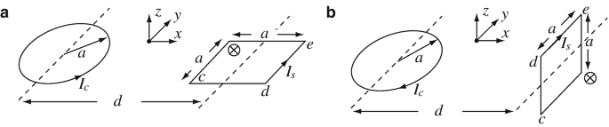
Figure 9.90
-
(a)


Rights and permissions
Copyright information
© 2021 Springer Nature Switzerland AG
About this chapter

Cite this chapter
Ida, N. (2021). Magnetic Materials and Properties. In: Engineering Electromagnetics. Springer, Cham. https://doi.org/10.1007/978-3-030-15557-5_9
Download citation
DOI: https://doi.org/10.1007/978-3-030-15557-5_9
Published:
Publisher Name: Springer, Cham
Print ISBN: 978-3-030-15556-8
Online ISBN: 978-3-030-15557-5
eBook Packages: EngineeringEngineering (R0)