
Abstract
Much of the discussion in the previous three chapters centered around lossless transmission lines. For these lines, the various relations were independent of conductivity of the materials involved. In fact, even for a distortionless transmission line, although an attenuation constant was present, all other basic properties of the line were independent of conductivity. The speed of propagation depended only on material properties of the line (ε and μ), and the phase constant and wavelength were also independent of conductivity of the line. If this is the case, are the conductors necessary? If so, what are their roles in the propagation of energy in the lossless or distortionless transmission line?
He alone is free who lives with free consent under the entire guidance of reason.
Baruch Spinoza (1632–1677),
philosopher
Access this chapter
Tax calculation will be finalised at checkout
Purchases are for personal use only
Notes
- 1.
The first mention of a waveguide was in 1894 by Sir Oliver Joseph Lodge (1851–1940). He discovered the effect when he surrounded a spark generator, of the type used by Hertz to demonstrate propagation of waves, with a conducting tube. Three years later, Lord Rayleigh (John William Strutt (1842–1919)) developed much of the theory of guided waves. However, waveguides did not feature in electromagnetics until the early 1930s, when experiments on their properties were conducted at Bell Laboratories, first for propagation in dielectrics (water) and later in air. The main impetus for their development was the then newly developed microwave tubes and work on radar. From then on, waveguides became the basis of microwave work and are used wherever transmission of significant power above about 1 GHz is required. The various optical fibers are also waveguides and their utility in communication is prevalent.
Author information
Authors and Affiliations
Corresponding author
Problems
Problems
17.1.1 TE, TM, and TEM Propagation in Parallel Plate Waveguides
-
17.1
Application: TM Modes in Parallel Plate Waveguides. A parallel plate waveguide is made of two strips, a = 20 mm wide, separated by d = 1 mm and air filled. Neglect edge effects. For an incident electric field intensity of magnitude Ei = 1 V, neglect edge effects and calculate at a frequency 20% above the lowest cutoff frequency:
-
(a)
The guide phase velocity, guide wavelength, and wave impedance for TM modes.
-
(b)
The electric field intensity everywhere along the line for TM modes.
-
(c)
The magnetic field intensity along the line for TM modes.
-
(d)
The instantaneous power density in the waveguide for TM modes.
-
(a)
-
17.2
Application: TE/TM Waves in Parallel Plate Waveguides. A parallel plate waveguide is made of two wide strips, separated by a fiberglass sheet d = 0.5 mm thick which has a relative permittivity of 3.5. Neglect any effects due to the edges of the strips (i.e., assume the strips are infinitely wide) and calculate:
-
(a)
The lowest TM mode possible.
-
(b)
The lowest TE mode possible.
-
(c)
If a wave at twice the lowest TE cutoff frequency propagates along the waveguide, calculate the wave impedance for the TE and TM modes and compare with the wave impedance for TEM modes.
-
(a)
-
17.3
Power Relations in Integrated Microstrip Line. In a microstrip line, the strips are separated a distance 0.8 mm and are 2 mm wide. The material between the strips is Silicon Oxide with a relative permittivity of 3.8. Neglect edge effects. For an incident electric field intensity Ei = 1 V/m, calculate:
-
(a)
The total time-averaged power propagated in the lowest TE mode at a frequency 30% above cutoff.
-
(b)
The total time-averaged power propagated in the lowest TM mode at a frequency 30% above cutoff.
-
(c)
Compare the results in (a) and (b) with the power propagated in the TEM mode at the same corresponding frequencies.
-
(a)
-
17.4
Propagation in Discontinuous Waveguides. Three parallel plate waveguide sections are connected as shown in Figure 17.24. The material between the plates is free space. Assume that the three waveguide sections operate in TE modes only. The source on the left supplies power at all frequencies between 1 MHz and 100 GHz. What is the lowest frequency signal received at the receiver?
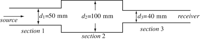
Figure 17.24
-
17.5
Reflection, Transmission, and SWR in Waveguides. A parallel plate waveguide with dimensions as shown in Figure 17.25 is very long. A slab of permittivity ε1 = 2.5ε0 [F/m] occupies the right half of the waveguide. Assume TE propagation from left to right, at f = 2 fc [Hz], where fc is the cutoff frequency of the empty waveguide. Calculate:
-
(a)
The reflection and transmission coefficients at the interface between air and slab.
-
(b)
The standing wave ratio in the waveguide to the left of the interface and to the right of the interface.
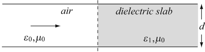
Figure 17.25
-
(a)
-
17.6
Fields in Shorted Waveguide. A parallel plate waveguide is made of plates 15 mm wide and separated a distance a = 1 mm. The space between the plates is air. The waveguide propagates in the lowest TM mode in the positive z-direction at a frequency 10% above cutoff. Assume the magnetic field intensity is directed out of the page in Figure 17.26 and has amplitude 20 A/m. Now a perfect conductor plate is used to short the two parallel plates (indicated by the dotted line) at z = 0. Calculate the electric and magnetic field intensities in the waveguide to the left of the short.
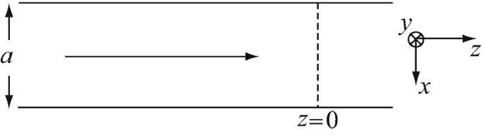
Figure 17.26
-
17.7
Application: Infrared Detection System. An infrared detection system is made of an optical microstrip line, used to guide infrared waves, and an infrared detector. The system must operate at a wavelength of 1,200 nm and the detector has an impedance of 50 Ω. The microstrip line is made of a thin sheet of glass, with relative permittivity εr = 1.75, sandwiched between two conducting sheets as shown in Figure 17.27. If the line is matched to the detector, calculate:
-
(a)
The lowest possible mode of propagation that may be used.
-
(b)
The thickness d of the glass sheet that will support the mode calculated in (a).
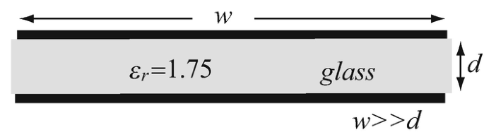
Figure 17.27
-
(a)
-
17.8
TEM Modes in Parallel Plate Waveguide. A parallel plate waveguide is made with planar conductors as shown in Figure 17.28b. Dimensions are b = 20 mm, d = 2 mm and the space between the plates is Teflon with a relative permittivity of 2.0. The peak magnetic field intensity at z = 0 is 3.8 A/m and the propagation is in the positive z direction. Find, assuming perfect conductors for the plates and perfect dielectric for the space between the plates:
-
(a)
The electric and magnetic field intensity for TEM modes as a function of frequency.
-
(b)
The power propagated in the waveguide.
-
(a)
-
17.9
TE Fields in Parallel Plate Waveguide. A parallel plate waveguide is made with planar conductors as shown in Figure 17.28a. Dimensions are b = 20 mm, d = 2 mm and the space between the plates is Teflon with a relative permittivity of 2.0. The peak electric field intensity at z = 0 is 240 V/m and the propagation is in the positive z direction. Find, assuming perfect conductors for the plates and perfect dielectric for the space between the plates:
-
(a)
The electric and magnetic field intensity at the center frequency (middle of the bandwidth) in the lowest TE mode.
-
(b)
The power propagated at the center frequency (middle of the bandwidth) in the lowest TE mode.
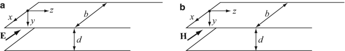
Figure 17.28
-
(a)
-
17.10
TM Fields in Parallel Plate Waveguide. A parallel plate waveguide is made with planar conductors as shown in Figure 17.28b. Dimensions are b = 20 mm, a = 2 mm and the space between the plates is Teflon with a relative permittivity of 2.0. The peak magnetic field intensity at z = 0 is 5 A/m and the propagation is in the positive z direction. Find, assuming perfect conductors for the plates and perfect dielectric for the space between the plates:
-
(a)
The electric and magnetic field intensity at the center frequency (middle of the bandwidth) in the lowest TM mode.
-
(b)
The power propagated at the center frequency (middle of the bandwidth) in the lowest TM mode.
-
(a)
-
17.11
Application: Dielectric waveguide. A plane electromagnetic wave propagates in a lossless dielectric sheet as shown in Figure 17.29. Relative permittivity of the dielectric is 2.25 and relative permeability is 1. The dielectric is 10 mm thick. Calculate:
-
(a)
The smallest incidence angle θ that will still allow propagation in the dielectric without light escaping through the top and bottom surfaces.
-
(b)
The lowest mode (frequency) of waves that can propagate in the dielectric sheet under the conditions in (a).

Figure 17.29
-
(a)


17.1.2 TM/TE Modes in Rectangular Waveguides
-
17.12
Application: Low-Frequency Waveguide–Limitations. An engineer had a bright idea: Why not use rectangular waveguides instead of the coaxial lines used in cable TV? The requirements are as follows: lowest frequency 54 MHz (TV Channel 2), and the waveguide has a ratio of a = 2b.
-
(a)
What must be the dimensions of the waveguide to propagate from 54 MHz and up in the TE10 mode?
-
(b)
The normal TV range in the VHF band is between 44 MHz and 88 MHz (channels 2 through 6) and from 174 MHz through 216 MHz (Channels 7 through 13) with each channel allocated 6 MHz bandwidth. How many of the TV channels can be propagated in the TE10 mode calculated in (a)?
-
(c)
Is this a bright idea?
-
(a)
-
17.13
Application: Mode Separation and Bandwidth. The commercial EIA WR 284 rectangular waveguide has internal dimensions a = 72.14 mm and b = 34.04 mm. Calculate:
-
(a)
The maximum bandwidth for the TE10 mode.
-
(b)
The maximum bandwidth for the TM11 mode.
-
(c)
The maximum bandwidth for the TE01 mode.
-
(a)
-
17.14
Application: Modes in Rectangular Waveguide. An EIA WR 112 standard, rectangular waveguide with dimensions a = 28.499 mm and b = 12.624 mm is used to connect to a radar antenna which operates at a wavelength of 20 mm. Find all propagating modes that can be used at the given wavelength. The waveguide is air filled.
-
17.15
Application: Fields and Power in Rectangular Waveguide. A rectangular waveguide is used to transmit power from a generator to a radar antenna. The waveguide is an EIA WR 34 waveguide with internal dimensions 8.636 mm and 4.318 mm, operating at 23 GHz in the TE10 mode. The power delivered is 50 kW:
-
(a)
Calculate the amplitudes of the electric and magnetic field intensities in the waveguide.
-
(b)
Are these amplitudes acceptable in level? Explain.
-
(a)
-
17.16
Application: Tunnels as Waveguides. The following communication system is proposed for communication in mine tunnels to avoid the need for cables: the tunnel is used as a waveguide 5 m wide and 2 m high.
-
(a)
What is the lowest frequency that may be used?
-
(b)
If it is desired to propagate a single mode, what is the maximum bandwidth that may be used and still guarantee propagation in the lowest mode?
-
(a)
-
17.17
Discontinuities in Rectangular Waveguide. A very long rectangular waveguide is filled with two materials as shown in Figure 17.30. A TM wave propagates in the waveguide from the left. Calculate:
-
(a)
The lowest frequency (cutoff frequency) that will propagate in the waveguide.
-
(b)
The time it takes the wave to propagate between points A and B.
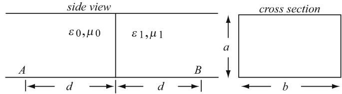
Figure 17.30
-
(a)
-
17.18
Field Required for Total Power. It is required that a lossless rectangular waveguide carry 100 W (time averaged power) at 4.5 GHz, in the TE10 mode. The waveguide is a = 47.549 mm wide and b = 22.149 mm high (EIA WR 187 waveguide) and is air filled:
-
(a)
Find the longitudinal and transverse components of the electric field intensity.
-
(b)
Find the longitudinal and transverse components of the magnetic field intensity.
-
(a)
-
17.19
Application: Reduced Height Waveguide. In most waveguides the height equals half the width because this choice improves mode separation (and hence bandwidth of modes). However, in some cases, a different ratio may be chosen for specific purposes. Consider the standard EIA WR 229 waveguide with dimensions a = 58.166 mm, b = 29.083 mm. The waveguide is also available in what is called the ½ EIA WR 229 with dimensions a = 58.166 mm, b = 14.500 mm (this is called a half-height waveguide). Calculate:
-
(a)
The first 10 lowest modes for the ½ EIA WR 229 waveguide and classify them as TE or TM.
-
(b)
Repeat (a) for the EIA WR 229 waveguide.
-
(c)
Compare the bandwidths of the various modes of the two waveguides.
-
(a)
-
17.20
Square Cross-section Waveguide. Most rectangular waveguides are made so that a = 2b, that is, their height is half their width. Suppose an air-filled waveguide is built so that a = b = 12 mm.
-
(a)
Calculate the first 8 TE modes and the first 8 TM modes.
-
(b)
From (a) explain why square cross-section waveguides are not a good idea.
-
(a)
-
17.21
Application: Power Carried in Lowest Mode. The EIA WR 137 waveguide has dimensions a = 34.849 mm, b = 15.799 mm. The half-height version is called the ½ EIA WR 137 and has dimensions a = 34.849 mm, b = 7.9 mm:
-
(a)
Find the lowest cutoff frequency and mode for the two waveguides.
-
(b)
Calculate the time-averaged power the wave can propagate at a frequency 25% above the cutoff in (a), for a given electric field intensity with amplitude E0 = 1,000 V/m for the two waveguides.
-
(c)
Which waveguide can carry more power for the same field level and why?
-
(a)
-
17.22
Maximum Power Handling of a Waveguide. A rectangular waveguide has a width to height ratio a/b = 2.0 and the ratio between the operating frequency and the cutoff frequency is f/fc10 = 1.25 at f = 10 GHz. What is the maximum time-averaged power that can be transmitted in the waveguide in the TE10 mode without exceeding the breakdown electric field intensity of 3 × 10⁶ V/m in air?
-
17.23
Application: Integrated Optical Waveguide. An integrated optical waveguide is made in the form of a rectangular cross-sectional channel in a silicon substrate, as shown in Figure 17.31. The channel is 2 μm wide, 1 μm high, and ε = 2ε0 [F/m]:
-
(a)
Explain why this structure can function as a rectangular waveguide and outline the conditions necessary for it to operate. Hint: Consider the conditions for total reflection in a dielectric.
-
(b)
Calculate the lowest frequency that can be propagated. Which mode is it and in what range of the spectrum is this propagation possible?
-
(c)
Calculate the peak power that can be propagated at a frequency 25% above the frequency calculated in (b) if the peak electric field intensity cannot exceed 1,000 V/mm.
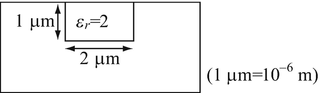
Figure 17.31
-
(a)
-
17.24
TM Waves in a Waveguide. Write the time domain expressions for the transverse components of the fields for TM propagation in a lossless rectangular waveguide of width a and height b (see Exercise 17.4).
-
17.25
TM Waves in a Waveguide. Find the total wave in a waveguide of width a [m] and height b [m] if a forward-propagating TM wave of amplitude E +0 [V/m] and a backward-propagating wave of amplitude E −0 [V/m] exist.
-
17.26
TE Waves in a Waveguide. Find the total transverse TE waves in a waveguide of width a [m] and height b [m] if a forward-propagating wave of amplitude H0 [A/m] and a backward-propagating wave of amplitude H1 [A/m] exists in the waveguide.


17.1.3 Attenuation and Losses in Rectangular Waveguides
-
17.27
Dielectric Losses in Waveguides. A rectangular waveguide is filled with a lossy dielectric with relative permittivity εr = 2 and conductivity σd = 10−4 S/m. Assuming perfectly conducting walls, find:
-
(a)
The attenuation constant in the waveguide at a frequency 1.5 times larger than the lowest cutoff frequency.
-
(b)
The percentage of power loss per meter of the waveguide at f/fc = 1.75. Assume the power entering a section of the waveguide is P0 [W] and calculate the power loss as a percentage of this power.
-
(a)
-
17.28
Conductor (Wall) Losses. A rectangular waveguide is made of aluminum, which has conductivity of 3.6 × 10⁷ S/m. The walls of the waveguide are thick and the internal dimensions are a = 38.1 mm and b = 25.4 mm. Assuming the waveguide is empty (free space), calculate:
-
(a)
The power loss per meter length in the TE01 mode at f/fc = 1.5. Assume the amplitude of the longitudinal magnetic field intensity is 1 A/m.
-
(b)
The attenuation constant due to losses in the walls for the conditions in (a).
-
(a)
-
17.29
Application: Waveguide with Dielectric and Wall Losses. The rectangular waveguide in Problem 17.28 is given again, but now the waveguide is filled with a low-loss dielectric with relative permittivity of 2 and conductivity σd = 10−4 S/m. All other parameters including wall conductivity remain the same. Calculate:
-
(a)
The attenuation constant in the waveguide for the TE01 mode at f/fc = 1.25.
-
(b)
The power loss per meter length in the TE01 mode at f/fc = 1.25. Assume the amplitude of the longitudinal magnetic field intensity is 1 A/m.
-
(a)
17.1.4 Cavity Resonators
-
17.30
Resonant Frequencies in Rectangular Cavity. A rectangular cavity resonator is 60 mm long, 30 mm high, and 40 mm wide and is air filled. Calculate:
-
(a)
The TE101 resonant frequency.
-
(b)
The next three nondegenerate TE resonant modes. Classify the modes.
-
(a)
-
17.31
Resonant Frequencies in Shorted Waveguide. The EIA WR 284 waveguide is made into a cavity 0.5 m long by shorting the waveguide at two locations. Calculate the first 10 resonant frequencies and classify the modes. The waveguide has dimensions a = 72.14 mm and b = 34.04 mm.
-
17.32
Application: Design of a Cavity for Given Resonant Frequencies. A cavity resonator is built from a section of a waveguide with dimensions a = 47.549 mm and b = 22.149 mm (EIA WR 187) by shorting the waveguide with two conducting plates to create a rectangular cavity of length d [mm]. The cavity is required to resonate at 8 GHz in the TM111 mode:
-
(a)
Find the length of the shorted section necessary.
-
(b)
What is the dominant mode and what is its resonant frequency?
-
(a)
-
17.33
Application: Microwave Moisture Sensor. A microwave relative humidity (RH) sensor is made as in Figure 17.21 by drilling holes in a cavity resonator to allow free movement of air. The cavity is 35 mm by 16 mm by 42 mm. The relative permittivity of dry air is 1.0 whereas at saturation humidity (100% RH) it is 1.00215. Assume permittivity increases linearly with relative humidity.
-
(a)
Calculate he shift in resonant frequency of the fundamental mode per % RH in the dominant mode.
-
(b)
If frequency increments of 1 kHz can be accurately measured, what is the resolution of the sensor in % relative humidity (% RH). Resolution is the smallest increment in % humidity that can be measured.
-
(a)
Rights and permissions
Copyright information
© 2021 Springer Nature Switzerland AG
About this chapter

Cite this chapter
Ida, N. (2021). Waveguides and Resonators. In: Engineering Electromagnetics. Springer, Cham. https://doi.org/10.1007/978-3-030-15557-5_17
Download citation
DOI: https://doi.org/10.1007/978-3-030-15557-5_17
Published:
Publisher Name: Springer, Cham
Print ISBN: 978-3-030-15556-8
Online ISBN: 978-3-030-15557-5
eBook Packages: EngineeringEngineering (R0)