
Abstract
In this chapter we will discuss the use of elastic solutions to predict the strength of parts containing sharp cracks. Immediately, we are faced with the difficulty that, whether we consider the line crack or the elliptical crack with semiminor axis shrunk to zero, the stresses at the crack tip are infinite for any value of load. Thus, the elastic solutions by themselves are not adequate for fracture prediction. Basically, two approaches have been taken in fracture calculations to overcome this dilemma without becoming involved in a detailed analysis of the “process zone” at the crack tip. One is based on energy considerations and takes advantage of the fact that the strain energy associated with the stress field around a crack is finite because the stress becomes infinite in an infinitesimally small region. The other makes use of the stress intensity factor to describe the state of stress in the crack tip region. At first sight it is perhaps confusing to have two different approaches but they can be shown to be equivalent.
This is a preview of subscription content, log in via an institution.
Buying options
Tax calculation will be finalised at checkout
Purchases are for personal use only
Learn about institutional subscriptionsNotes
- 1.
Griffith’s paper [3] shows \( \left(1-{v}^2\right) \) in the denominator.
- 2.
Several factors may have been involved in this result. First, Griffith’s equation was in error by a factor equal to Poisson’s ratio. With this correction for ν = 0.26, his value for γ fracture would be 2400 ergs/cm2. This compares well with more recent fracture surface energy measurements made over the same loading times (0.5–5 min). In addition, two important factors ignored by Griffith may have been involved. He annealed his specimens after producing the cracks. It has been shown [12] that this may increase strength as much as sixfold relative to unannealed specimens. An opposing factor is that Griffith applied the flat plate solution to cracks in pressurized spheres and cylinders. As we will see later, for the dimensions used by Griffith, this may lead to as much as a threefold decrease in fracture stress relative to flat plate values for a similar crack size.
- 3.
In other than two-dimensional problems, e.g., the thumbnail crack, we may have to be cautious in comparing a global approach G with a local approach K, when K varies with location.
References
Griffith AA. Philos Trans R Soc Lond. 1920;A221:163–98.
Gordon JE. The new science of strong materials, vol. A920. Harmondsworth: Pelican Books Ltd; 1968.
Griffith AA. Proc. 1st Int. Cong. Appl. Mech., Delft, Holland; 1924. p. 53–64.
Spencer AJM. Int J Eng Sci. 1965;3:441–9.
Sneddon IN. Proc R Soc Lond. 1946;187A:229–60.
Sack RA. Proc Phys Soc. 1946;58:729–36.
Linger KA, Holloway DG. Philos Mag. 1968;18:1269.
Gilman JJ. J Appl Phys. 1960;31:2208–18.
Congleton JA, Petch NJ. Acta Metall. 1966;14:1179–82.
Orowan E. Fracture and strength of solids. Rep Prog Phys. 1948;12:185–232.
Berry JP. J Polym Sci. 1961;50:107–15. 313.
Berg CA. Proc. Joint International Conference on Creep, Inst. Mech. Engineering, London; 1963. p. 1.41–1.47.
Irwin GR. Fracture dynamics, fracturing of metals. Cleveland: ASM; 1948. p. 147 (see also many later references).
Orowan E. Trans Inst Eng Shipbuilders (Scotland). 1945;89:165–215.
Eshelby JD. Solid state physics, vol. 3. New York: Academic; 1956.
Rice JR. Trans ASME J Appl Mech. 1968;35:379–86.
Barenblatt GI. In: Dryden HL, von Karman T, editors. Advances in applied mechanics, vol. 7. New York: Academic; 1962. p. 55–129.
Rooke DP, Cartwright DJ. Compendium of stress intensity factors. UK: H.M.S.O.; 1976.
Sih GC. Handbook of stress-intensity factors. Bethlehem, PA: Lehigh University; 1973.
Tada H, Paris P, Irwin GP. The stress analysis of cracks handbook. Hellertown, PA: Del Research Corp; 1973.
Vaidyanathan S, Finnie I. Trans ASME J Basic Eng. 1971;93D:242–6.
Paris PC, Sih GC. Fracture toughness testing and applications. ASTM STP. 1965;381:30–83.
Erdogan F, Ratwani M. Nucl Eng Des. 1972;20:265–86.
Green AE, Sneddon IN. Proc Camb Philos Soc. 1950;46:159–63.
Kobayashi AS, Moss WL. Proc. 2nd Int. Conf. on Fracture, Brighton, England. London: Chapman and Hall; 1969.
Cribb JL, Tompkin B. J Mech Phys Solids. 1967;15:135–40.
Irwin GR. Trans ASME J Appl Mech. 1957;24:361–4.
Willis JR. J Mech Phys Solids. 1967;15:151–62.
Bueckner HF. Trans ASME. 1958;80:1225–9.
Davidge RW, Tappin G. The effective surface energy of brittle materials. U.K. Atomic Energy Authority Report AERE—R5621, 1967.
Simpson LA, Wasylyshyn A. The measurement of work of fracture of high strength brittle materials. Atomic Energy of Canada Report AECL—3677, Feb 1972.
Obreimoff JW. Proc Roy Soc. 1930;A127:290–7.
Author information
Authors and Affiliations
Problems
Problems
-
1.
Mica, a transparent almost ideally brittle material, can be cleaved, as shown below, by a smooth rigid wedge. One cannot measure the force P in such an experiment, but the deflection y of the cleaved strip near the crack front can be measured optically by counting interference fringes. Obreimoff [32] made such an experiment and for h = 0.011 cm found
$$ \begin{array}{ll}y=0.04{x}^2\hfill & \mathrm{where}\ x\ \mathrm{and}\ y\ \mathrm{are}\ \mathrm{in}\ \mathrm{centimeters}.\hfill \end{array} $$Treating the cleaved strip as a cantilever of length a, and ignoring shear deflections, you are asked to estimate G c (dyn/cm) for Obreimoff’s muscovite mica. We recall that the deflection curve of a cantilever of length a with end load P is given by
$$ \begin{array}{lll}y=\frac{P}{EI}\left(\frac{a{x}^2}{2}-\frac{x^3}{6}\right)=\frac{Pa{x}^2}{2EI}\hfill & \mathrm{if}\hfill & x\ll a\hfill \end{array} $$Take E for mica as 2 × 10¹² dyn/cm2.
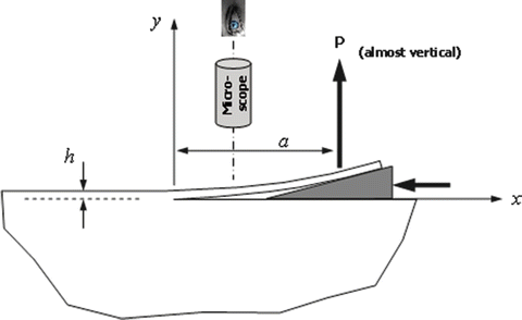
(assume unit width perpendicular to paper).
-
2.
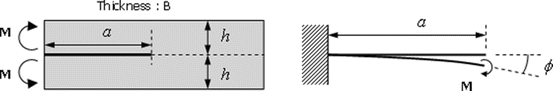
It has been proposed that fracture tests be conducted on double cantilever beam specimens loaded by end moments as shown. Recalling that the end rotation ϕ of a cantilever beam of length a is given by \( \phi = Ma/EI \), you are asked to obtain an approximate value for K I for this specimen for plane strain conditions. Express the result in terms of M and the specimen dimensions.
-
3.
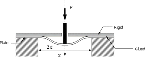
To measure the fracture toughness G c of an adhesive joint, the test sketched below has been proposed. The strain energy of a plate clamped at its rim and centrally loaded is given by
$$ \begin{array}{lllll}U=\frac{8\pi D{x}^2}{a^2}\hfill & \mathrm{where},\hfill & D=E{h}^3/12\left(1-{v}^2\right)\hfill & \mathrm{and}\hfill & x=\frac{P{a}^2}{16\pi D}\hfill \end{array} $$You are asked to obtain an expression for G in terms of P, D, and any other quantities involved.
-
4.
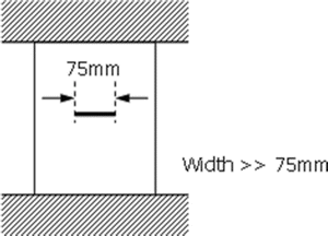
A plate, as shown below, is clamped at the ends but no external loads are applied. If the ambient temperature decreases but the grips do not move, then an axial tensile stress will be developed in the plate (transverse stresses can be neglected well away from the grips). For a high-strength steel plate 1 in. thick with the properties given below, you are asked to estimate the temperature change that will cause catastrophic propagation of a 75 mm long through crack:
-
Young’s modulus, E = 200 GPa
-
Coefficient of thermal expansion, α = 10.8 × 10⁻⁶/°C
-
Critical crack energy release rate, G Ic = 5250 J/m2
-
Yield strength, S y = 1400 MPa
-
Poisson’s ratio, ν = 0.3
Assume plane strain and no change of G Ic with temperature which may be a reasonable assumption if we are considering moderate changes in temperature. Also neglect any corrections.
-


Rights and permissions
Copyright information
© 2016 Springer Science+Business Media New York
About this chapter
Cite this chapter
Dharan, C.K.H., Kang, B.S., Finnie, I. (2016). The Basis of Linear Elastic Fracture Mechanics. In: Finnie's Notes on Fracture Mechanics. Springer, New York, NY. https://doi.org/10.1007/978-1-4939-2477-6_4
Download citation
DOI: https://doi.org/10.1007/978-1-4939-2477-6_4
Publisher Name: Springer, New York, NY
Print ISBN: 978-1-4939-2476-9
Online ISBN: 978-1-4939-2477-6
eBook Packages: EngineeringEngineering (R0)