
Abstract
Connecting the devices in our lives, from toasters to fitness devices, to each other and to the Internet is the fundamental principle of the Internet of Things (IoT). Enabling this connectivity requires at the very least a direct connection to the Internet, but often data is routed and processed at a local network stage before being passed to the Internet. Some sensor networks are not connected to the Internet at all, and their data is simply aggregated and displayed at a local aggregation point, such as a smart phone or PC. The topology of the sensor network depends largely on the overall system application: a personal area network may simply stream data from all sensors to a single central aggregator (star topology), whereas a home monitoring network may use a self-healing mesh topology. The different sensor topologies and the applications to which they are most suited are discussed in this chapter.
You have full access to this open access chapter, Download chapter PDF
Keywords
These keywords were added by machine and not by the authors. This process is experimental and the keywords may be updated as the learning algorithm improves.
Connecting the devices in our lives, from toasters to fitness devices, to each other and to the Internet is the fundamental principle of the Internet of Things (IoT). Enabling this connectivity requires at the very least a direct connection to the Internet, but often data is routed and processed at a local network stage before being passed to the Internet. Some sensor networks are not connected to the Internet at all, and their data is simply aggregated and displayed at a local aggregation point, such as a smartphone or PC. The topology of the sensor network depends largely on the overall system application: a personal area network may simply stream data from all sensors to a single central aggregator (star topology), whereas a home monitoring network may use a self-healing mesh topology. The different sensor topologies and the applications to which they are most suited are discussed in this chapter.
As more and more devices are connected to the Internet, big data challenges emerge: volume, velocity, variety, and veracity. Sensor data is cheap to generate, but expensive to move, store, and manage. Not all data is useful. The sensor network, or more specifically the aggregator on the sensor network, has a key role in aggregating data: identifying which data should be presented to the user or a remote network and which data should be discarded. The earlier data is processed in the sensor lifecycle, the cheaper the overall system will be. Increasingly capable, low-power, low-cost devices are being developed for this edge-processing role. We discuss these aggregation devices in detail in this chapter.
Managing large numbers of different sensors across a sensor network is a challenging task, particularly if the sensors are deployed in remote locations. Cloud-based sensor-network management tools are becoming increasingly popular. These tools provide real-time network status information, the ability to remotely change a sensor’s configuration, and basic data storage and visualization. Many popular cloud-based services can be quickly integrated with popular sensor platforms, such as Arduino. Therefore, they are becoming a popular tool for the maker community and IoT enthusiasts. The most popular sensor-network management tools and their sensor interfaces are discussed and compared at the end of this chapter.
Sensor Network Components
A sensor network consists of a group of smart sensors that are wired or wirelessly connected to another smart sensor or to a common aggregator. In networking terminology, each component in the network that has a communications module is called a node. A node that generates data is called a source node, while a node that requests data is called a sink or sink node. A sink can be another sensor node on the network, a gateway to another larger network, or a local aggregator. A source node can report routine data, an alert, or maintenance data. The sensor network performs two key tasks: data gathering and data dissemination. Data gathering is term used to describe the capture and transfer of data from each sensor node to a sink. The source sends data to the sink periodically or on demand, and the sink processes the data. Data dissemination is the term used to describe the process for routing queries or data around the sensor network. Data dissemination is a two-step process. In the first step, the sink node describes the data it is interested in and broadcasts this descriptor, which is called “interest,” across the network. Each node maintains an interest cache of all data to be reported. In the second step, the nodes that have data of interest send this data to the sink.
Sensor networks can consist of a number of the same types of sensors distributed over a region, providing the same sensor data (a homogenous sensor network); or they may involve a number of different sensors (a heterogeneous sensor network), which provide different sensor data to the system. Homogenous sensor networks can be applied to extend the sensing region of a sensor. For example, a network of weather sensors distributed across a city can provide richer information than a single weather sensor placed in a solitary location, and could even be applied to study microclimates across the city. In this scenario, a homogenous network, sensing the same range of target parameters over a different region can also offer a degree of fault tolerance, as spurious data from a single sensor in the network could be identified by comparing it to data from neighboring sensors. This spatial sensor redundancy can also be applied, along with prediction-monitoring techniques, to reduce unnecessary transmission of events, thus making the sensor network more energy-efficient (Hongbo, 2011). Another application of homogenous networks could be using the same sensor type to measure different aspects of a system. For example, a personal area network, in which an inertial sensor is connected to each limb, would produce different data from each limb. In this scenario, the sensor network can capture and synchronize data from each sensor, allowing the end user to examine the motion of each limb in comparison with the others for a given period of time.
Heterogeneous sensor networks integrate data from different sensor types into the system. The different data sources are typically used for a common purpose. A home alarm system is a typical example of a heterogeneous network. These systems feature magnetic switches to detect the opening and closing of windows and doors and passive infrared sensors to detect motion. The network may also contain an actuator, such as a siren, to raise an alert if a home intrusion is detected. Although the sensing modality differs in all these devices, the purpose of each device is the same—to detect an intrusion.
Wireless sensor networks (WSNs) are a subset of sensor networks, and consist of a sink node, which is usually called a “base station,” and a number of wireless, battery-powered sensor nodes. The base station typically has significantly higher processing and data storage capabilities than the other nodes on the network. A base station is often AC-powered, but this is not always the case. A smartphone can act as a base station in a wireless personal area network (WPAN) despite being battery-powered; the smartphone will have significantly more battery power than the sensor nodes in the network and will be regularly charged. The lifetime of the sensor network depends on how well the energy consumption of the sensing and processing of the communications components of the WSN node are balanced against the battery life. Selection of low-power radios and efficient network protocols and messaging are key factors in extending the lifetime of the WSN.
Sensor Nodes
A sensor node is a smart sensor that is capable of gathering sensory information, performing some processing, and communicating with other connected nodes on the network. Smart sensors are discussed in detail in Chapter 3. Sensor platforms such as Arduino allow users to connect sensor and communications modules to a base platform. The ability to seamlessly interchange hardware radio modules means users can change not only their communication protocol but also the network topology employed. For example, replacing a Wi-Fi module with an XBee 868 module allows the user to replace a star-based network with a self-healing mesh network that has a wider sensing range.
Aggregators, Base Stations, and Gateways
Sensor nodes require a collection point where the data can be processed, stored, or forwarded onward to other networks via longer-range and higher-throughput wired or wireless communications mechanisms. A variety of terms are used to describe various data collection and translation points in sensor networks. Computing devices, such as M2M devices or PCs, can be configured to act as aggregators, gateways, bridges, base stations, or coordinators, which can lead to confusion in the meanings of these terms. The complexity of the network architecture or the domain in which they’re applied can also influence the term used to describe a particular function. In an attempt to clarify, we offer the following definitions:
-
Routers forward data packets between two or more computer networks.
-
Gateways perform protocol translation between different networks. A gateway can operate at any network layer, and, unlike a router or a switch, a gateway can communicate using more than one protocol. PCs, servers, and M2M devices can function as gateways, although they are most commonly found in routers. In a sensor network, a gateway is responsible for interfacing the data from the sensor nodes to another network that uses a different protocol, and delivering commands back from that network to the nodes. Gateways work on OSI layers 4-7.
-
Bridges connect two or more network segments along the data link layer (OSI layer 2) to create an aggregate network.
-
Aggregators are sink nodes, which capture raw data from the nodes in the sensor network and reduce the overall size of the data by aggregating redundant or correlated data. This decreases the volume of network traffic and the energy consumption of the system, thus reducing cost.
-
In WSNs, a base station is a node that has far more computational, energy, and communication resources than the other sensor nodes. A base station typically acts as a gateway between sensor nodes and the end user as its role is to forward data from the WSN to a server.
-
In a Zigbee network, a coordinator node is responsible for managing the sensor network. Specifically, the coordinator acts at the network layer to select the frequency channel to be used by the network, starts the network, and allows other devices to join the network. The coordinator can also provide message routing, security management, and other services.
Machine-to-Machine Devices
Machine-to-machine (M2M) devices are networked devices that can exchange information and perform actions without the manual assistance of humans. An M2M system includes sensors, a back-haul communications link, such as cellular or Wi-Fi, and application software, which can automatically interpret data and make decisions. M2M systems are often used for remote monitoring or automation tasks in which sensor inputs and the decision tree are clearly defined. A common example of an M2M system is a vending machine, which can alert a distributor when a particular item is running low. Initially used only in scientific, engineering, and manufacturing domains, M2M technology is becoming increasingly relevant to end users as more and more home devices have network connectivity and open data interfaces. M2M technology is now found in heating units, water meters, and even in coffee makers ( www.nespresso.com/pro/aguila/#/aguila /pro/aguila/#/aguila). Devices with M2M communications capabilities are often marketed to end users as “smart” devices.
There is currently no standard M2M radio or messaging protocol, although many de facto standards, such as MQ Telemetry Transport (MQTT) messaging, are beginning to emerge. As the IoT concept continues to grow and M2M becomes more pervasive, it is widely expected that vendors will have to agree on standards for device-to-device communications.
In recent years, the number of M2M devices has dramatically increased. They can be sold as components in an end-to-end solution or as standalone devices that must be configured by the user. An M2M device is simply a piece of hardware that can be configured by software to operate as part of an M2M solution. The software components of an end-to-end solution are discussed in more detail later in this chapter.
Proprietary M2M solutions
Proprietary solutions, such as the Libelium Meshlium M2M device ( www.libelium.com/products/meshlium /products/meshlium), provide out-of-the-box connectivity between a manufacturer’s sensor solution and its cloud solution. Proprietary solutions provide a quick and easy method to transfer data from predefined sensors to a predefined cloud. The software in a proprietary solution is typically optimized to interface with the manufacturer’s own sensors using a predefined messaging protocol over a predefined radio. It is usually difficult to interface sensors from another manufacturer with the system. The key advantage of a proprietary solution is ease of use for the end user, who can typically configure a sensor network using a web interface on the M2M device or a cloud solution. Preexisting knowledge of a sensor type and messaging protocol allows the manufacturer to add advanced features, such as over-the-air programming, to the system’s management suite without the complexity of supporting numerous device types.
Smartphones
Smartphones are discussed in Chapter 2 as sensor platforms, due to their integrated sensors and processing and communication abilities. However, smartphones can also act as M2M devices that can aggregate data from external sensors and other data sources, store and analyze data, and interface with cloud-based services. The key advantage of smartphones as M2M devices is the number of sensor devices available to connect to them. Smartphone “app-enabled accessories,” such as smart watches or blood-pressure monitors, can interface with a smartphone over a physical or wireless connection using a messaging protocol defined by the operating system. The Apple App Store and Google Play provide intuitive access to a repository of software apps that can interface with these sensors and actuators. These apps are proprietary software written by the sensor manufacturer or a third party and are designed to interpret and process data from a proprietary sensor. Apps may also upload data to proprietary cloud-based storage for long-term tracking. Although the processing and communications specifications of smartphones and traditional M2M devices are fundamentally very similar, they differ greatly in their application software. A traditional M2M device is typically a headless device that can operate with little or no user interaction for years at a time. It has a single purpose: to aggregate data from numerous sources into a single database for analysis and decision-making and trigger the appropriate response when an event is detected. Although a smartphone can perform the same data capture, processing, and decision-making tasks as an M2M device, it is primarily a phone and an entertainment device. The processing, data storage, and display features of each app are independent of the processing, data storage, and display features of other apps on the device. This siloing of data, though important for security purposes, is inefficient and makes it difficult for the user to make interesting correlations between data captured from different apps.
Traditional M2M Platforms
There has been a rapid increase in the number of low-power M2M-capable devices in recent years. ARM-based devices, such as the Raspberry Pi (aspberrypi.org) and BeagleBoard (beagleboard.org), have been widely used by the maker community as M2M devices for monitoring and actuation projects. These boards can be interfaced with sensors and actuators using the onboard general-purpose input/output (GPIO) headers, and a hardware ecosystem has developed to create sensor shields for these devices. The USB interface on the board can be used to add radio dongles that interface with wireless sensors or provide wireless Internet connectivity over Wi-Fi or general packet radio service (GPRS). The Intel Galileo (arduino.cc/en/ArduinoCertified/IntelGalileo), shown in Figure 4-1, is a 32-bit microcontroller that is hardware and software pin-compatible with the Arduino 1.0 pinout. It is therefore compatible with the hundreds of existing Arduino shields and can be programmed using the Arduino IDE. The Galileo board also features two USB ports and a full-sized mini-PCI Express slot, which can be used to add Wi-Fi, Bluetooth, GSM cards, or a solid-state drive. Both the ARM and Intel-based devices run embedded Linux (eLinux) distributions. An eLinux distribution, such as Raspbian or Yocto, is becoming the de facto standard for M2M operating systems. It provides a familiar interface to users who are already familiar with Linux on PCs and servers and allows users to leverage thousands of existing free and open source packages for networking, multimedia, and data processing.

The Intel Galileo board (photo courtesy of Intel)
The RaspberryPi, BeagleBoard, and Intel Galileo are currently used only by hobbyists and are not part of any integrated device-to-cloud solution, although platform-as-service providers such as Xively (xively.com) and Device Cloud (etherios.com/products/devicecloud) supply APIs to interface these devices to their cloud storage platforms. The Kontron M2M Smart Services Developer Kit is a commercial solution that includes an Intel Atom-based M2M device, a Wind River IDP operating system, and Cumulocity Device Cloud. The Kontron M2M device has integrated Wi-Fi, 802.15.4, and USB interfaces to connect to sensors and Wi-Fi, Ethernet, and GPRS to communicate with the device cloud.
Sensor Network Topologies
In chapter 3 we looked at the architectures of sensors, smart sensors, and sensor systems. They typically combine sensing, processing, communication, and power subsystems in a single integrated system. While sensors can be used in isolation for specific applications, multiple sensors are commonly integrated into higher-level topologies to deliver real world applications. These topologies can vary in complexity from a single node connected to an aggregator to fully meshed networks distributed over a large geographical area. Sensor topologies can also be described as having either a flat or hierarchical architecture. In a flat (peer-to-peer) architecture, every node in the network (sink node and sensor node) has the same computational and communication capabilities. In a hierarchical architecture, the nodes operate in close proximity to their respective cluster heads. Hence, nodes with lower energy levels simply capture the required raw data and forward it to their respective cluster heads. Usually the cluster heads possess more processing and storage capacity than any ordinary sensor node. The most common forms of network topologies are shown in Figure 4-2. Sensor networks that are physically wired together commonly use star, line, or bus topologies. Wireless sensors networks are often built using star, tree, or mesh topology configurations:
-
Point-to-point topology links two endpoints, as shown in Figure 4-2 (a). This topology can be permanent or switched. A permanent point-to-point topology is a hardwired connection between two points. A switched connection is a point-to-point connection that can be moved between different end nodes. This topology is commonly used in many of the applications described in Chapters 9–11, where a single sensor is used with a smartphone or tablet acting as a data aggregator
-
Bus topology is a configuration in which each node is connected to a shared communication bus, as shown in Figure 4-2 (b). A signal is transmitted in both directions along the bus until it reaches its intended destination. Bus networks must include a collision avoidance system to resolve issues when two nodes simultaneously send out data on the bus. Bus networks are simple and easy to install. However, there is a single point of failure: if the bus fails, the entire network fails.
Figure 4-2. 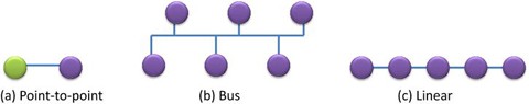
Graphical representation of (a) point-to-point, (b) bus, and (c) linear network topologies
-
Linear topology is a two-way link between one node and the next node, as shown in Figure 4-2 (c). There are two terminating nodes at the end of the network that have a single connection to a nearby node, and all other nodes are connected to two other nodes. In this topology, the nodes depend on each other to propagate a message to the next node. If a node fails, any nodes connected to that node are disconnected from the network.

-
Ring topology is a network set up in a circular fashion, as shown in Figure 4-3 (a). It is similar to a linear topology, in which the end nodes are connected to each other. In this configuration, each node connects to exactly two other nodes and data flows in one direction from the source to each node until it finds the intended recipient. This topology is easy to install and reconfigure. However, it is costly to manage as a ring network can be disturbed by the failure of a single node. Many networks add a second communication ring that can transmit data in the opposite direction to overcome this issue. This topology was a common way to link small offices and schools, but is rarely used anymore.
-
Star topology consists of a single “central node,” such as a hub or a switch that every node in the network connects to, as shown in Figure 4-3 (b). This topology is easy to design, implement, and extend. All data traffic flows through the central node; therefore, an intelligent central node is required. Failure of this node will result in failure of the entire network. The star network topology is one of the most common sensor network topologies. A wireless personal area network (WPAN), consisting of a smartphone connected to several wireless sensors, is a common example of this topology.
Figure 4-3. 
Graphical representation of (a) ring, (b) star, and (c) tree network topologies
-
Tree topology is a hierarchy of nodes in which the highest level of the hierarchy is a single “root node,” and this node is connected to one or many nodes in the level below, as shown in Figure 4-3 (c). A tree topology can contain many levels of nodes. The processing and power in nodes increase as the data moves from the branches of the tree toward the root node, allowing data to be processed close to where it is generated. This topology is scalable and the simple structure makes it easy to identify and isolate faults. Tree networks become increasingly difficult to manage as they get larger.

-
Mesh topology nodes disseminate their own data and also act as relays to propagate the data from other nodes. There are two forms of mesh topology: a partially connected mesh, in which some nodes are connected to more than one other node, shown in Figure 4-4 (a); and a fully connected mesh, in which every node is connected to every other node in the mesh, shown in Figure 4-4 (b). Mesh networks are self-healing, as data can be routed along a different path if a node fails. Fully connected mesh networks are not suitable for large sensor networks as the number of connections required become unmanageable. Partially connected mesh networks provide the self-healing capability of a fully connected network without the connection overhead. Mesh topologies are most commonly found in wireless networking.
Figure 4-4. 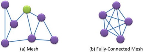
Graphical representation of (a) partially connected and (b) fully connected mesh network topologies

Sensor networks can also be described by their logical topology—the method they use to move data around the network. There are two types of logical topology: shared media and token-based. In the shared media topology, all nodes can access the transport media when they want. This can lead to collisions, which must be managed by a collision-avoidance protocol. This logical topology is used in bus, star, or hybrid physical topology networks, due to their shared data bus or shared node. In a token-based logical protocol, a token is passed around the network. If a node wishes to send data, it must get the token from the network. When the data arrives at its destination, the token is released and continues travelling around the network. The token method is most useful in a ring-based topology.
Sensor Network Applications
In the application domain, sensor networks are more commonly described by their application type than their network or logical topology. For example, a personal area network (PAN) transfers personal data, can be a star network or a point-to-point network, and can use any of a number of low-power, short-range radios to communicate. This section describes the most common applications of sensor networks in the health, wellness, and environmental-monitoring domains.
Personal Area Networks
Personal area networks connect computing devices, such as laptops, tablets, or smartphones, to each other or to other devices in proximity. These devices can be connected using wired (USB/serial cable) or wireless (infrared, Bluetooth, Bluetooth LE) interfaces. The data exchanged between devices on a PAN are typically of a personal nature (photos, files). It is therefore important to have some form of basic security to prevent unauthorized use of the network. Wireless personal area networks (WPANs) were originally developed as a cable replacement technology for personal electronic devices. WPANs can be categorized into one of three broad categories, according to their data throughput and power consumption (Misic et al., 2008):
-
High data rate WPANs: Real-time multimedia applications based on IEEE 802.15.3 (the IEEE standard for multimedia streaming over wireless personal area networks). The standard supports up to 245 wireless fixed and portable devices at speeds up to 55Mbps over distances up to 100 meters.
-
Medium data rate WPANs: The IEEE 802.15.1 Bluetooth standard was designed to be a cable replacement for consumer devices. Bluetooth supports data rates up to 3Mbps. This standard has been widely adopted for sensor-based WPAN applications.
-
Low data rate WPANs: These networks can be based on either Bluetooth or 802.15.4, which support data rates up to 250 Kbps.
The terms body area network (BAN) or wireless body area network (WBAN) are often used interchangeably with WPAN. WBANs are built on WPAN technologies to specifically implement communications on, near, or around the human body, as shown in Figure 4-5. A WBAN can include a number of sensor types depending on the requirements of the application. Wireless body area networks typically integrate pedometers, heart rate and respiration monitors, and so forth (see Chapters 9 and 10) with a smartphone or computing device. WBANs provide greater flexibility than wired PANs. This is particularly useful in diagnostic applications, where extended monitoring is required. WBANs are also very useful for supporting diagnostic protocols in which the sensors must not impact or limit patient performance during the course of a test. Smart clothing, which integrates sensors into clothing and textiles, provides accurate data as it is in direct contact with most body skin surface. Moreover, smart clothing is generally noninvasive and has minimal impact on the wearer; therefore, it is ideal for extended ambulatory health-monitoring applications (Fabrice et al., 2005). The use of sensors for smart clothing is discussed in more detail in Chapter 10.

Wireless body area network
The FCC has approved a specific frequency for the implementation of medical body area network (MBAN) systems. Devices communicating on this protected spectrum allocation (between 2360–2400 MHz) experience less interference from ubiquitous unlicensed radio devices, such as Bluetooth, Zigbee, or Wi-Fi.
Ambient/Pervasive Home Sensor Networks
In the near future, homes will contain distributed networks of intelligent devices that will transparently sense the user and adapt the environment in an intelligent, personalized manner. To achieve this goal, each home must contain a large-scale distributed network of sensors, actuators, and display devices. This will require an intelligent backend, which can not only react to real-time events but also predict upcoming events and act accordingly. A simple example of pervasive sensing is a bed sensor that detects whether someone wakes in the middle of the night and activates low-level lighting along the path to the bathroom to ensure that he doesn’t trip in the dark.
There are numerous challenges in implementing a pervasive sensor network, not the least of which are data interference, data mining, and data modeling. From a sensing and networking perspective, the communications protocol is a key question. Should all nodes in the home use the same Zigbee or Z-wave communication protocol? If so, an industry protocol must be defined to ensure that consumers have a wide range of sensors that can use that protocol. Alternatively, should the house be able to adapt to different communications protocols and allow wearable devices to seamlessly join the home network and upload their data to it? The communication network of a ubiquitous home system should meet certain requirements. In the first place it should support interoperability, so terminals are easy to add, replace, or remove. The sensor nodes must be self-describing and require minimal configuration by the user to install.
Wide Area Networks
A wide area network (WAN) is a network that covers a broad area (for example, any telecommunications network that links across metropolitan, regional, or national boundaries) using private or public network transports. Business and government entities utilize WANs to relay data among employees, clients, buyers, and suppliers from various geographical locations. In essence, this mode of telecommunication allows a business to effectively carry out its daily function regardless of location. The Internet can be considered a WAN as well, and is used by businesses, governments, organizations, and individuals for almost any purpose imaginable. WANs can be thought of as computer networking technologies used to transmit data over long distances, and between different local area networks (LANs), metropolitan area networks (MANs), and other localized computer networking architectures. This distinction stems from the fact that common LAN technologies operating at Layers 1 or 2 (such as the usual forms of Ethernet or Wi-Fi) are often geared towards physically localized networks, and thus can’t transmit data over long distances. WANs do not just necessarily connect physically disparate LANs. A campus area network (CAN), for example, may have a localized backbone of a WAN technology, which connects different LANs within a campus. This could be to facilitate higher bandwidth applications or provide better functionality for users in the CAN.
WANs are used to connect LANs and other types of networks, so that users and computers in one location can communicate with users and computers in other locations (see Figure 4-6). Many WANs are built for one particular organization and are private. Others, built by Internet service providers, provide connections from an organization’s LAN to the Internet. WANs are often built using leased lines. At each end of the leased line, a router connects the LAN on one side with a second router within the LAN on the other. Leased lines can be very expensive. Instead of using leased lines, WANs can also be built using less costly circuit-switching or packet-switching methods. Network protocols, including TCP/IP, deliver transport and addressing functions. Protocols including packet over SONET/SDH, MPLS, ATM, and frame relay are often used by service providers to deliver the links that are used in WANs. X.25 was an important early WAN protocol, and is often considered to be the “grandfather” of frame relay as many of the underlying protocols and functions of X.25 are still in use today (with upgrades) by the frame relay protocol.

A wide area wireless sensor network
Sensor Network Features and Challenges
Software is pervasive at all levels of a sensor network, and the complexity of the software varies depending on which level of the sensor network the software is running and the capabilities of the microprocessor on that device. A solar-powered, wireless, environmental sensor node may simply capture data from the sensor, perform simple processing, and transmit to a higher-capability M2M device according to a predefined messaging protocol. An M2M device can aggregate data from multiple sensor nodes, store the data, perform more complex processing, and transmit data to another M2M device or a cloud server for additional aggregation and processing. Application services display the data from the aggregation devices on a computer application, web page, or smartphone app. Although the complexity of the software and the capability of the processor vary greatly at each level of a sensor network, the software on each device in the sensor network hierarchy contains the following features (Figure 4-7):
-
Communications: Each device has the ability to transfer data to other devices in the sensor network hierarchy. The lowest order sink nodes in the network are usually wireless and battery-powered and must therefore implement a very low-power radio protocol. The software on sink nodes must manage power consumption by powering the radio off when the node is not transmitting. Aggregation devices, such as M2M devices or smartphones, are typically AC powered or regularly charged. These devices usually feature one or more radios to communicate with the sensor network and at least one method to backhaul the data to the Internet. The software on an aggregation device must be able to manage data transmitted over multiple radios. An application device can be an Internet-enabled device that interfaces with the aggregation device’s API over the Internet, or the application and aggregation software may both reside on a single device, such as a smartphone.
-
Messaging: The traditional way to send a message between two devices is to agree on a message protocol and transfer data between the devices according to that protocol. If a different device type is added to the network, a new message protocol must be defined, and the gateway must interpret both protocols. This method is inefficient and costly, as it transmits data regardless of whether the gateway device is interested in the data. It is also not scalable to create a new protocol for each new device type. A number of protocols have been developed to address these inefficiencies and enable scalability. MQTT (mqtt.org), a lightweight publish/subscribe messaging transport, is becoming the de facto M2M connectivity standard for IoT and low-power or low-bandwidth sensor networks. All messages are sent to an MQTT message broker, which distributes messages to clients that have declared an interest in the message topic. The ability to subscribe to messages saves both processing and transport costs.
-
Processing: Data transmission and data storage are costly at every stage of a sensor network. It is therefore vital that sensor data is processed and reduced as close to where it is generated as possible. The processing capability of a device is dependent on the microprocessor and power constraints of the device. A low-power edge node on a wireless network may have limited processing capability but may perform basic processing, such as calculating the mean to reduce the volume of data to be transmitted. M2M devices are more powerful devices, capable of analyzing data from multiple sources, inferring trends and events from the data, and deciding which data can be discarded. In many M2M monitoring applications, the status of a system may be stable for several hours or days, so all data captured from these devices may be discarded. If an event is detected, the data used to generate that event can be held by the M2M device for additional analysis by a higher-capability device. The processing and data storage capabilities offered by cloud services allow the performance of complex analytics on big data using tools such as hadoop ( hadoop.apache.org ). Big data analytics and data visualization are discussed in more detail in Chapter 5.
-
Storage: The memory required on a smart sensor device is dependent on the sensor application. A sensor node in a WBAN that continually transmits raw data to a smartphone device requires minimal data storage. But a 3-lead electrocardiogram (ECG) Holter monitor, which captures data at 256Hz, requires significant storage to capture data for up to 48 hours. Smart sensors rarely contain the memory or processing capability to maintain an embedded database. Therefore, data is typically stored as flat files in the smart sensor’s data memory or on an SD card. M2M devices have sufficient storage and processing capability to host an embedded transactional database such as Sqlite ( sqlite.org ). Most eLinux distributions contain the Sqlite application or at least the ability to download the software in a single command. The Sqlite database can be accessed natively on the console or using a Python, C++, or Java application library. The eLinux operating system and associated programming languages also contain libraries to query or write data to remote databases on other devices using SQL statements. There are many software options for data storage in the cloud, ranging from MySQL ( mysql.com ) for managing small to medium datasets, to distributed databases such as Cassandra ( cassandra.apache.org ) or MongoDB ( mongodb.org ) for managing “big data.” The data in the databases can be queried or updated from the application device through APIs.
-
Manageability: Device manageability is one of the most critical tasks in a sensor network. The sensor network manager must be able to remotely configure the sensors in his or her network, upgrade software, run diagnostics, and be alerted if a sensor is unresponsive. A sensor network that can’t be remotely managed is a non-scalable sensor network. A number of cloud-based services, such as Xively and Device Cloud, have emerged in recent years, to provide cloud-based device manageability. Both services offer libraries that can be installed on an IP-addressable sensor or gateway device, a method to register new devices on the cloud-based management console, and a manageability console that allows the sensor network manager to view status and remotely configure the devices on the network. These services also provide basic data storage, basic data analytics capabilities, and APIs for application devices and services to interface to the data and the network.

Functional representation of software components in a sensor network
Security
Security is a key requirement for many sensor applications. This is particularly true where the sensor must collect and forward sensitive health data. For wireless sensors, the question of whether someone can intercept the data is never far away. An in-depth analysis of sensor security is beyond the scope of this book, and many excellent texts deal with that topic in great detail. We will look at the key areas relevant to our application domains. Sensors have certain key challenges with respect to security as they are normally resource-constrained devices: they have limited computation, memory, and power resources, and limited communication speed and bandwidth.
Sensors can be used to provide security in a system by identifying individuals. This form of sensing is known as biometrics. In biometric security approaches, unique characteristics of individuals, such as the electrical characteristics of their hearts, can be used to identify them. This form of security is starting to appear in consumer devices, such as fingerprint identification on laptops and smartphones. In this way, sensors can be used to secure access to other sensor data sets.
Key Security Goals
The goal of security in a sensor network is to protect both the individual sensor node and the network from malicious attacks that may emerge either internally or externally. The key security requirements that are important in helping to maintain the integrity of a network are as follows:
-
Data confidentiality: This is normally the highest priority goal, and focuses on making the sensor inaccessible to unauthorized users through activities such as eavesdropping. This is particularly important for applications that utilize multiple sensor streams, such as WBANs. Attackers can infer information about an individual by correlating the data streams. The most common approach to protect the data is to use ciphers to encrypt the data.
-
Data integrity: The focus is on ensuring the data received has not been altered in any way, either by malicious action or by accidental communication errors during the transmission process. Integrity-checking is typically implemented by cryptographic hashes that are similar to cyclic redundancy checks (CRC). Common hashes include MD5 and SHA.
-
Authentication: Authentication enables either the sensor node or the aggregators to ensure the identity of the sensor or aggregator it is communicating with. Various mechanisms can be used for authentication, including the exchange of authentication keys or digital signatures. These approaches allow a party to prove its identity. They also protect against forgery or masquerading.
-
Non-repudiation: Non-repudiation ensures that a sensor node can’t deny sending a message it previously sent. Digital signatures combined with public key infrastructures are a common mechanism for implementing non-repudiation.
-
Authorization: Authorization ensures that only approved nodes can access network services or specific destinations.
-
Freshness: Freshness-checking ensures that sensor data messages are current, ordered, and unduplicated. From a security perspective, this prevents the replay of old messages in an attack. Freshness is normally implemented through the use of sequence numbers and timestamps in the packets transmitted by the sensor.
Attacks on Sensor Networks
The key security issue for most sensors is a malicious attack. Wireless sensor networks are vulnerable to attacks such as message spoofing or message replays. Attacks can be categorized as either internal or external. An external attack can be either active or passive (Hongbo, 2011). Attacks can also be classified based on the network layer the attack attempts to exploit.
In a passive attack, unauthorized eavesdropping or listening to sensor messages occurs. This form of attack can be thwarted using encryption. An active attack on a network aims to disrupt the normal function of the network. Attacks using a denial-of-service (DoS) approach are commonly employed. Attacks of this type include signal jamming and repetitive queries to drain the sensor’s battery (denial-of-sleep attack). Many attacks of this nature can be prevented with robust authentication mechanisms. Jamming is generally addressed through the use of spread-spectrum or frequency-hopping communications such as Bluetooth. Other forms of external attack include tampering, resulting in the physical capture of the sensor node. While it can difficult to prevent physical interference with sensors nodes, the nodes can react to the detection of tampering by erasing cryptographic keys and firmware/programs from system memory (Chaos Computer Club, 2013).
An internal attack occurs when an attacker compromises the security of an individual sensor node and uses that node to disrupt or prevent the network from any useful function. Common attacks of this nature include Sybil, node-replication attack, Hello flood attack, selective forwarding, and sinkhole attack / black holes (Serbanati et al., 2011).
Security Approaches
Security for sensor networks can be divided into two broad categories: cryptography and intrusion detection. A variety of robust cryptographic implementations are available for WSNs, such as 128-bit AES-based encryption with multiple keys. But these solutions can have significant computational overhead and, as a consequence, significant power requirements. In additional, infrastructure may be required for key management, distribution, and authentication.
Intrusion detection focuses on detecting and responding to anomalies in the network, which may result from an attack such as a Wormhole or Sybil. Intrusion detection is referred to as second-line defense because it can’t prevent an attack but only identify when one is occurring. Intrusion detection systems (IDS) are generally rule-based or anomaly-based. A rule-based IDS detects intrusions using predefined attack signatures. It can detect known attacks with great accuracy, but has difficulty detecting new attacks where a signature does not exist. An anomaly-based IDS detects intrusion by matching traffic patterns or resource utilizations. The anomaly detection approach can be useful at finding both known and new forms of attack. It can also suffer from high false positive and false negative rates (Drahanský, 2011).
Currently no truly end-to-end security solution exists for WSNs. Realizing a robust solution will be challenging due to the heterogeneous nature of the WSNs, varying node resource capabilities, usage models, and so forth.
As the importance of smartphone and tablets as sensor aggregators continues to grow, so do the associated risks. These devices have the potential to carry sensitive personal health data that requires protection. For applications that use discrete sensors that communicate with smartphones or tablets via a wireless connection, securing that connection between the sensor and smartphone is crucial. For example, Bluetooth implements confidentiality, authentication, and key derivation with custom algorithms based on the SAFER+ block cipher. For integrated sensors within the devices, a secure wireless link is not a concern. However, data stored on the device must be protected and remain secure at all times during its lifetime on the device, as well as during transmission of the data to another location such as a cloud service. Products such as AuthenTec MatrixDAR are available to support these requirements. However, in the future we are likely to see more security integrated directly into the hardware and operating system to deliver data features such as secure enclaves. Such features will be augmented with explicit user and platform environment policies to control sensor data access and processing. These features will also inform users when their data is or is not protected. The security platform will automatically manage data access requests by other applications and services, either local or cloud-based, depending on device policies.
Biometrics
Security for sensor applications typically focuses on securing sensor data during transmission from the sensor to an aggregator or from sensor to sensor in a multi-hop WSN. Sensors can also be used to provide security to a system in the form of biometric detection. Biometric techniques are used to identify an individual on the basis of a unique physical, physiological, behavioral, or biological characteristic. The robustness of biometrics as a form of security is based on the assumption that these characteristics are either impossible or at least very difficult to replicate or mask. Another key advantage of biometric security is that the identification process requires no passwords, ID cards, security fobs, and so forth. This can make it more convenient and potentially less costly than traditional security approaches. A variety of approaches exist, including facial recognition, fingerprinting, retinal scans, and DNA analysis. We will focus on approaches that require the use of sensors in the identification process.
-
Fingerprint biometrics is one of the most widely used biometric approaches. It works by examining a finger’s dermal ridges for verification or authentication. There are two main methods of fingerprint acquisition. The first approach involves a touch sensor on the user’s fingertip to detect the peaks and valley of a fingerprint. The second approach is based on the use of a swipe sensor. The user places her finger on a designated starting point and in a continuous and smooth motion, swipes over a sensor. The sensor samples at a predefined frequency and then assembles the multiple readings into one image. Both approaches have the advantages of usability and acceptability. Additionally, the swipe sensor can be easily integrated into mobile form factors such as laptops or smartphones. Fingerprint sensors are generally either optical or solid state. Optical sensing is based on imaging the fingerprint and using algorithms to process the image. Solid state sensors acquire the fingerprint using techniques such as capacitive, thermal, conductivity, and pressure measurements. In both methods, the acquired data is translated into a set of distinguishing features used to uniquely identify an individual. Fingerprint biometrics is not foolproof. A number of techniques have been demonstrated that can spoof a person’s fingerprint using readily available household items, as highlighted by the iPhone 5S fingerprint hacking (Chaos Computer Club, 2013). The security of fingerprint biometrics can be enhanced by including a liveness indicator in the identification process to verify that the measured characteristics come from a live human being. There are a number of techniques to measure liveness in biometrics, including perspiration, blood oxygenation, and response to hot and cold stimulus (Drahanský, 2011).
-
EKG/ECG biometrics approaches use the heart’s electrical impulses for user authentication. Distinctive characteristics such as the heart’s position and size, chest configuration, and other features produce a unique ECG signal (Israel et al., 2005). An advantage of ECG-based authentication over other biometrics is the fact that an ECG signal can be extracted from the surface of the skin and measures the heart’s activity, which makes ECG highly universal and easy to collect. Another key advantage is that it is non-trivial to spoof and can also be used as a liveness indicator. ECG biometrics is still in its infancy, with various research questions such as uniqueness, permanence, and scalability to be addressed before it can appear in consumer products.
-
Electroencephalogram (EEG) biometrics: An EEG provides a profile of brain electrical activity. It can potentially be used for biometric authentication because the human brain consists of neurons and synapses that are configured uniquely for each individual. EEG signals are typically broken into alpha (8-13 Hz), beta (14-30 Hz), and theta (4-7 Hz) rhythms. Features such as center frequency, maximum power, and sum power for each rhythm can be analyzed for identification purposes (Lin et al., 2011). A limitation of this approach, however, is the ability to produce cost-effective systems. Although consumer-level EEG readers are available, it is debatable whether this level of device can acquire EEG signals that are accurate enough to be used in biometric authentication. Also, sensors are currently too obtrusive for regular use, and the signals are sensitive to environmental noise.
-
Gait: Biometric identification of an individual based on walking style has been reported in the literature (Derawi et al., 2010). Gait is commonly measured using body-worn sensors or sensors integrated into a handheld device, such as a smartphone. In practice, this approach suffers from a variety of issues, including sensitivity to the sensor location on the body, foot injury, disease, intoxication, pregnancy, and weight loss or gain. Another approach is the use of floor sensors, which have the advantage of being unobtrusive and can provide accurate gait data for identification purposes. However, floor sensors can only be used in the physical locations in which they are installed, and the cost of these sensors can be prohibitive.
Challenges for Sensor Networks
There are a number of technical and domain-specific challenges in implementing and maintaining a sensor network. These range from power considerations for “deploy and forget” sensors that are used for environmental monitoring, to the biocompatibility of body-worn sensors used for health and wellness applications. The most common challenges are:
-
Power sources: Sensor nodes must be capable of harvesting or generating enough energy to meet their operational requirements. A sensor node that is not energy self-sufficient over a substantial lifetime (hours for an ingestible sensor, several days for a rechargeable, wearable sensor, or years for an environmental sensor) is not scalable. The power consumption and power generation challenges for sensor networks are being met on several fronts. First, battery technology is continually improving, providing longer battery life in smaller form factors. Second, power consumption due to data communication is improving as lightweight messaging protocols and low-power radio modules are introduced. Third, advances in processor technology have resulted in lower-power processors. Finally, advances in the power generated by, and the form factors of, solar cells, fuel cells, thermal cells, and biochemical cells mean that these are becoming increasingly practical ways to power sensor nodes.
-
Autonomic nodes and networks: The ability of sensor nodes and a sensor network to operate with minimal human interaction is essential for developing truly scalable large sensor networks. This is achieved by using predefined policies and rules that enable the individual nodes and the network to manage and configure themselves.
-
Reliability and security: Data security and reliable transport are key sensor network priorities, particularly in the health domain. However, these add high overhead in terms of data size, power consumption, and scalability to the system. Critical diagnostic health data must be protected and securely transferred, regardless of overhead. A balance may be found, though, by transferring less critical data. Can the data rate be reduced? Does anonymized fitness data require the same level of security as personal health records? These decisions will have to be made on an application-by-application basis, and appropriate hardware and software solutions will be required to meet these challenges.
-
Durability: Body-worn and ambient sensors are subject to numerous environmental challenges. Environmental sensors installed in an urban environment are subject to rain, wind, UV exposure, dirt, and perhaps vandalism. Body-worn sensors are subject to accidental or intentional submersion, friction with clothing, and scratching against other objects. The sensor must be durable enough to survive these conditions and able to operate reliably for extended periods, regardless of environmental conditions.
-
Biocompatibility: The effects of long-term sensor contact with the human body are yet not well understood. The biocompatibility of sensor materials is becoming increasingly important, as people begin to wear sensors for months or years at a time. For example, ECG electrodes must be replaced after 7 to 10 days of direct skin contact to minimize skin irritation. The topic of biocompatibility will become increasingly important as in-vivo sensing becomes more prevalent.
-
Privacy and data ownership: Personally identifiable data is a valuable commodity that must be protected whenever data is collected or transferred. Each country has legally enforceable data-protection guidelines, which must be complied with when collecting any data that includes personal information. Environmental sensors may unintentionally capture personal data, such as a conversation between individuals while recording traffic noise. Regardless of intent, such data must be protected and transferred using appropriate security measures. The issue of data ownership arises when data is sold or transported between different parties. In the health domain, data transfer and privacy are essential elements of any ethical-approval or device-regulation submission and should therefore be agreed on in advance of using any sensor technology.
Summary
This chapter introduced the topic of sensor networks and topologies by describing the hardware and software components of a sensor network and the various ways in which they may be configured. Common sensor network applications, including personal area networks, were described, and the challenges for current and future sensor networks were discussed.
References
Hongbo, Jiang, “Prediction or Not? An Energy-Efficient Framework for Clustering-Based Data Collection in Wireless Sensor Networks,” IEEE Transactions on Parallel and Distributed Systems, vol. 22 (6), pp. 1064–1071, 2011.
Misic, Jelena and Vojislav Misic, “Prologue: Wireless Personal Area Networks,” in Wireless Personal Area Networks: Performance, Interconnection, and Security with IEEE 802.15.4, Chichester, England, John Wiley & Sons Ltd, 2008, pp. 3–16.
Chaos Computer Club. “Chaos Computer Club breaks Apple TouchID”, Last Update: November 2013, http://www.ccc.de/en/updates/2013/ccc-breaks-apple-touchid /en/updates/2013/ccc-breaks-apple-touchid
Serbanati, Alexandru, Carlo Maria Medaglia, and Ugo Biader Ceipidor, Building Blocks of the Internet of Things: State of the Art and Beyond, 2011.
Drahanský, Martin, “Liveness Detection in Biometrics,” in Advanced Biometric Technologies, Chetty, Girija, Ed., InTech, 2011, pp. 179–198.
Israel, Steven A., John M. Irvine, Andrew Cheng, Mark D. Wiederhold, and Brenda K. Wiederhold, “ECG to identify individuals,” Pattern Recognition, vol. 38 (1), pp. 133–142, 2005.
Lin, Jia-Ping, Yong-Sheng Chen, and Li-Fen Chen, “Person Identification Using Electroencephalographic Signals Evoked by Visual Stimuli,” in Neural Information Processing. vol. 7062, Lu, Bao-Liang, Liqing Zhang, and James Kwok, Eds., Springer Berlin Heidelberg, 2011, pp. 684–691.
Derawi, M. O., C. Nickel, P. Bours, and C. Busch, “Unobtrusive User-Authentication on Mobile Phones Using Biometric Gait Recognition,” in Intelligent Information Hiding and Multimedia Signal Processing (IIH-MSP), 2010 Sixth International Conference on, 2010, pp. 306–311.
Conti, Mauro, Irina Zachia-Zlatea, and Bruno Crispo, “Mind how you answer me!: transparently authenticating the user of a smartphone when answering or placing a call,” presented at the Proceedings of the 6th ACM Symposium on Information, Computer and Communications Security, Hong Kong, China, 2011.
Korotkaya, Zhanna, “Biometric Person Authentication: Odor”, Lappeenranta University of Technology http://www2.it.lut.fi/kurssit/03-04/010970000/seminars/Korotkaya.pdf /kurssit/03-04/010970000/seminars/Korotkaya.pdf, 2003.
Gibbs, Martin D., “Biometrics: body odor authentication perception and acceptance,” SIGCAS Comput. Soc., vol. 40 (4), pp. 16–24, 2010.
Chigira, Hiroshi, Atsuhiko Maeda, and Minoru Kobayashi, “Area-based photo-plethysmographic sensing method for the surfaces of handheld devices,” presented at the Proceedings of the 24th annual ACM symposium on User interface software and technology, Santa Barbara, California, USA, 2011.
Spachos, P., Gao Jiexin, and D. Hatzinakos, “Feasibility study of photoplethysmographic signals for biometric identification,” in Digital Signal Processing (DSP), 2011 17th International Conference on, 2011, pp. 1–5.
Author information
Authors and Affiliations
Rights and permissions
Open Access This chapter is licensed under the terms of the Creative Commons Attribution-NonCommercial-NoDerivatives 4.0 International License (http://creativecommons.org/licenses/by-nc-nd/4.0/), which permits any noncommercial use, sharing, distribution and reproduction in any medium or format, as long as you give appropriate credit to the original author(s) and the source, provide a link to the Creative Commons licence and indicate if you modified the licensed material. You do not have permission under this licence to share adapted material derived from this chapter or parts of it.
The images or other third party material in this chapter are included in the chapter’s Creative Commons licence, unless indicated otherwise in a credit line to the material. If material is not included in the chapter’s Creative Commons licence and your intended use is not permitted by statutory regulation or exceeds the permitted use, you will need to obtain permission directly from the copyright holder.
Copyright information
© 2013 Michael J. McGrath
About this chapter
Cite this chapter
McGrath, M.J., Scanaill, C.N. (2013). Sensor Network Topologies and Design Considerations. In: Sensor Technologies. Apress, Berkeley, CA. https://doi.org/10.1007/978-1-4302-6014-1_4
Download citation
DOI: https://doi.org/10.1007/978-1-4302-6014-1_4
Published:
Publisher Name: Apress, Berkeley, CA
Print ISBN: 978-1-4302-6013-4
Online ISBN: 978-1-4302-6014-1
eBook Packages: Professional and Applied ComputingApress Access BooksProfessional and Applied Computing (R0)