
Abstract
The objective of our work is the study of the influence of the dynamic load due to the use of the explosive in the stability of the slope of an open pit mine, for this purpose we used the method of limit equilibrium to calculate the value of the safety factor through the geotechnical software SLIDE. On the one hand the calculation was carried out under static loading and on the other hand the dynamic loading is taken into account, which allowed us to conclude that the dynamic load influences the safety coefficient. Finally, a proposal to stabilize the slope at through a reprofiling of the bench is presented.
You have full access to this open access chapter, Download conference paper PDF
Keywords
- Critical Safety Factor
- Mine Slope Stability
- Limit Equilibrium Method
- Natural Geographic Boundary
- Lutetian Limestone
These keywords were added by machine and not by the authors. This process is experimental and the keywords may be updated as the learning algorithm improves.
1 Introduction
As the mining method is turning from open pit mining to sag by mining, the vertical height of open-pit mine slope continues to increase, the slope deformation and failure mode has close relationship with regional geological structure characteristics and the rock mass structure feature, the stability is influenced largely by rock mass, joints and fissures, and blasting vibration (Qiao and Li 2004). Particularly, open-pit mine’s productive blasting vibration and rainfall has an important effect on the mine slope stability. Productive blasting vibration has an indirect dangerous damage on the high and steep slope. It is mainly caused by blasting seismic wave after the blasting, especially for the joint fissures development. The high and steep rock slope containing a fault or fracture zone is more likely as this (Li et al. 2006). The rock instabilities occur when a number of factors come together, and for one reason or another, the state of precarious stability prevailing until then passes an unstable situation resulting in rocks characterized by displacement their types (sliding, flowing, falling), (Chalhoub 2006).
The stability calculation can be performed in two distinct circumstances; before or after the out break of the movement. In the first case, the slope is apparently stable; the purpose of stability calculation is to define a sliding surface that would have the best chance of appearing. In other words, the stability calculation allows both to assess the safety margin is on this side of the break, set the site the most threatened areas of instability and examine the influence some work (earthworks, buildings, blasting, earthquakes). On the safety margin which has been defined for the virgin slope. This calculation step, therefore, seems very important because it allows choosing the necessary parameters for the work to ensure the stability of the whole (book and website). Unlike the first case, and when the movement has already appeared on the slope, the stability calculation is performed to assess the safety margin between the current state of the site of the equilibrium state. In this second case, the parameter values necessary to introduce in the calculation are normally given by the investigations already carried out on site, are real values such as: The geometry of the surface of the slide, the Geotechnical characteristics of the massive and the sliding surface, etc. In this case, the stability calculation also of great interest because it can identify the causes of the emergence of the movement and define the work of consolidating, devices necessary to limit the risk (Faure 2000).
According to Schroeder (2010), the different forms of rock slope instabilities depend on factors “internal” own the massive relate to nature, to the morphology of rock masses and the characteristics of discontinuities that effect, and factors “external” can be natural or related to human activities.
2 Geological Setting
Jebel Onk is located in the North East of Algeria, in the eastern end of the mounts of Nemenmcha; last membered of the Saharan Atlas. It is the natural geographic boundary between the high plateaus Constantine and the Saharan area (Cieslinski et al. 1985, 1987); (Prian and Cortiel 1993). The study of the site area HAS year Approximately 250 hectares and belongs to the Sami mining basin Metlaoui than mine phosphate (SW Tunisia) (Mokadem et al. 2014). It contains approximately half the phosphate reserves of Algeria (Estimated at 2 trillion tons of reserves) (Amiour Dass et al. 2013), (Fig. 1).

Location map of the study area.
According to the report made by EREM Cieslinski et al. 1985 to 1987, the deposit Kef-Essnoun is located south of the massif of Jebel Onk 4 km from the town of Bir El-Ater, the administrative headquarters of the region (Daira) is 2 km to the west of Djemi-Djema deposit between Jebel Moufe and Jebel Tarfaye. The coordinates of this deposit are x = y = 951 500 and 168.0 to 170.0.
The pit is excavated as benches with slope angles of 75° to 85°, 30 m in height, and 10 m in width, (Fig. 2). The depth of the base of mine is 70 m. The thickness of the phosphate layer is about 50 m; the barren covering Consists of a series of Y Persian dolomite limestone with flint, locally Overcome by lutetium limestone, Miocene sands, and quaternary alluvium.

Quarry of Kef Essnoun before sliding.
3 Study of Instability
Following the great landslide, which took place on September 8, 2007 in the North East side of the quarry, a large mass of rock broke off from the solid, almost completely filling the pit (estimated volume of 6,000,000 m3), (Fig. 3).

Geological section of the studied slope (Kef-Essnoun) after sliding.
According to the geological section and the position of the sliding surface at the lamination joint (marl interface phosphate), the slip is classified as a plan year. The expert reports on this shift has resulted in the fact that the probable causes of this hazard are attributed to some geological factors and operating (Benaissa 2003).
3.1 Geological Factors
-
Presence of marl interface phosphates;
-
The presence of a near-vertical recovery of the layer of marl, which allows the mass detached, is following a true inclined plane;
-
The highly tectonized character of the massif.
3.2 Operating Factors
-
Very straightened Front, almost vertically from the figure to a height of 70 m;
-
Reduced dimensions of the berm;
-
Presence at the foot of the front layer of marl, which played a key role in the sliding of the whole;
-
The cumulative effect of shooting with explosives on the platform.
After this shift, operation has been shifted to the west side and southwest.
However, cracking was observed in February 2013, about 250 m upstream of the platform, suggesting a beginning of a new potential slip, (Fig. 4). The observed cracks are located along the outcrops of marl located stratigraphically below the level of the exploited phosphates. The most likely cause of this cracking is related much more to the vibrations generated by the rock blasting, fire with explosives that a landslide primer.

Changes in cracks.
4 Methodology
In this article, we will examine the current stability of the northern flank of Kef Essnoun, (Fig. 5), and provide a potential risk of instability represented by a safety factor determined by the limit equilibrium methods (SLIDE). In our case study, the parameters used were identified in the available data submitted by the company. They come from previous tests at a laboratory in accordance with standard AFNOR Eurocode 07 (XP P 94-010), Table 1.

Study site profile.
To achieve the modeling according to selected software, sections were cut along the northern flank of Kef-Essnoun to have profiles, with the thicknesses of the different facies.
5 Analysis of Stability
According to observations carried out on the site, it was deduced that the slippage affects the layer of marl. Given the lack of data regarding this facies of our study site, we opted the results of analysis of the old sliding whose geological conditions are comparable to those of current place of study to determine the most likely Geotechnical characteristics. This is to trace the value of cohesion and internal friction angle of marl, compatible for the 2007 landslide, with a critical safety factor (SF = 1).
According to the analysis results showing the variation of SF in terms of cohesion and internal friction angle of the facies of marl is found that a value of a critical safety factor (SF = 1): C = 45 kPa and φ = 14°.
The next step is to study the stability with or without the influence of vibration induced by blasting is simulated by integrating the parameter ground acceleration induced earthquake, the value obtained for horizontal and vertical acceleration estimated respectively at: Ah/g = 0.05 and Av/g = 0. 0125.
Where; Ah/g - horizontal acceleration of gravity; Av/g - vertical acceleration of gravity.
5.1 Phase Calculation
Static Load
We chose three calculation methods: Spencer, Bishop and Janbu, (Fig. 6).

The sliding surface and the safety factor value (static load).
SF of the values calculated according to the three methods mentioned previously shown in the following Table 2. According to the results of the safety factor, the limit equilibrium method (SLIDE), and static load (effect explosives), we find that the northern flank of Kef-Essnoun is stable, (Fig. 6).
Dynamic Load
SF of the values calculated according to the three methods mentioned previously shown in the following Table 3. For the same Geotechnical characteristics (specific gravity, cohesion, friction) and dynamic load (effect explosives): Ah/g = 0.05 and Av/g = 0. 0125, we find that the northern flank of Kef Essnoun is unstable and the break line is localized more exactly at the phosphate marl interface, (Fig. 7).

The sliding surface and the safety factor value (dynamic load).
5.2 Proposal of a Method of Reinforcement
According to the analysis conducted earlier results, adequate reinforcement method to stabilize our study site is profiling. It consists of:
-
The reduction of the crest to a level thus making it possible to eliminate the effect of the straightening of the layers, (Fig. 8).
Fig. 8. 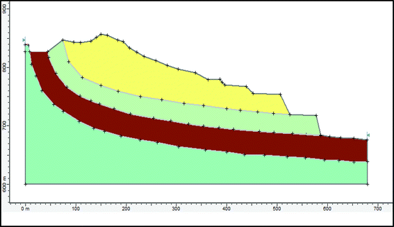
Reduction of the crest.
-
Creation of bench a height of 15 m to increase stability with the creation and widening of the platforms, (Fig. 9).
Fig. 9. 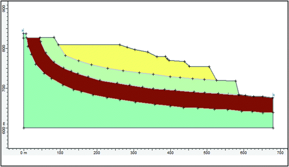
Creation of stands and expanding platforms.
-
Profiling bleachers and platforms, (Fig. 10).
Fig. 10. 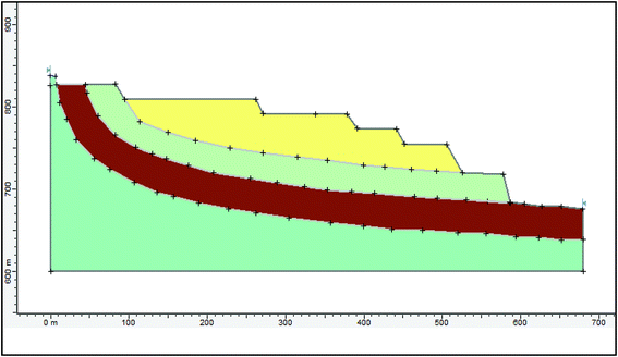
Reprofiling: bleachers and platforms.
-
The reinforcement method chosen made it possible to increase the safety factor and thus to ensure the stability of the site, (Fig. 11).
Fig. 11. 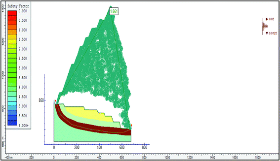
The sliding surface and the safety factor value with the dynamic load after reprofiling.


According to the result, it is found that profiling makes it possible to increase the stability with Safty Factor of the order of 1.66.
6 Conclusions
The analysis of the results allows us to say that in addition to the geological and geotechnical factors that can influence the stability of a slope, the dynamic loading due to the explosive must be taken into account. The control of this parameter can be achieved by reducing the height of the bench, the widening of the working platform and the modification of the operating method of exploitation.
References
Dass Amiour, M., Mezghache, H., Elouadi, B.: The use of three physico-chemical methods in the study of the organic matter associated with the sedimentary phosphorites in Djebel Onk Basin, Algeria. Arab. J. Geosci. 6, 309 (2013). doi:10.1007/s12517-011-0381-9
Benaissa, A.: Glissements de terrain: Calcul de stabilité, 2éme édition. Edition office des publications universitaires, Alger (2003)
Chalhoub, M.: Apports des méthodes d’homogénéisation numériques a la classification des massifs rocheux fracturées. Thèse de doctorat, Ecole Nationale Supérieure des Mines de Paris, spécialité géologie de l’ingénieur, pp. 39–45 (2006)
Cieslinski, S., et al.: Travaux de prospection et d’évaluation des phosphates de la région de Bir El Ater, EREM, pp. 3–10, 14–26, 39–44, 62, 63, 73–84, inédit (1985, 1987)
Faure, R.M.: L’évolution des méthodes de calcul en stabilité des pentes partie I méthodes à la rupture, Revue Française de Géotechnique (2000)
Li, W., Wang, J., Dai, L.: Safety criterion of blasting shock for the high deep slope of open-pit in mountain area. Ind. Miner. Process. 1, 20–22 (2006)
Mokadem, N., Hamed, Y., Ben Saad, A., Gargouri, I.: Atmospheric pollution in North Africa (ecosystems-atmosphere interactions): a case study in the mining basin of El Guettar-M’Dilla (southwestern Tunisia). Arab. J. Geosci. 7(5), 2071–2079 (2014)
Prian, G.P., Cortiel, P.: Etude de développement du gisement de phosphate de Djebel Onk (Algérie). Rapport d’expertise géologique, B.R.G.M. France, pp. 11–29, 133–149, 169–173, inédit. (1993)
Qiao, L., Li, Y.: Engineering geological model of high-steep slope damage in open cut mines. J. Univ. Sci. Technol. Beijing 26(5), 461–464 (2004)
Schroeder, C.: Etude de stabilité des parois rocheuses. Revue de société Belge de géologie de l’ingénieur et de mécanique des roches (SBGIMR), pp. 15–18, 21–29, 34 (2010)
Acknowledgments
The author would like to thank the staff of the mining laboratory of the Annaba University (Algeria). Also, a special thanks to A. Hafsaoui (Annaba University - Algeria) and to Boukarm R (Bejaia University - Algeria) for her objective comments and corrections.
Author information
Authors and Affiliations
Corresponding author
Editor information
Editors and Affiliations
Rights and permissions
Copyright information
© 2018 Springer International Publishing AG
About this paper
Cite this paper
Fredj, M. et al. (2018). Study of Slope Stability (Open Pit Mining, Algeria). In: Frikha, W., Varaksin, S., Viana da Fonseca, A. (eds) Soil Testing, Soil Stability and Ground Improvement. GeoMEast 2017. Sustainable Civil Infrastructures. Springer, Cham. https://doi.org/10.1007/978-3-319-61902-6_1
Download citation
DOI: https://doi.org/10.1007/978-3-319-61902-6_1
Published:
Publisher Name: Springer, Cham
Print ISBN: 978-3-319-61901-9
Online ISBN: 978-3-319-61902-6
eBook Packages: Earth and Environmental ScienceEarth and Environmental Science (R0)