Abstract
This paper examines the fidelity requirements for flight simulators to improve training and address the problems associated with rotorcraft loss of control in-flight (LOC-I). To set the context, trends in rotorcraft accident statistics are presented. The data show that, despite recent safety initiatives, LOC-I rotorcraft accidents have been identified as a significant and growing contribution to accident rates. In the late 1990s, the fixed-wing commercial aircraft community faced a similar situation relating to upset prevention and recovery, and through a coordinated international effort, developed a focussed training programme to reduce accident rates. Lessons learned from the fixed-wing programme are presented to highlight how improved rotorcraft modelling and simulation tools are required to reduce rotorcraft accidents through higher quality, simulator-based training programmes. Relevant flight simulator certification standards are reviewed, with an emphasis on flight-model fidelity and vestibular motion cueing requirements. The findings from rotorcraft modelling and motion cueing research, that highlight relevant fidelity issues, are presented to identify areas for further activities to enhance the fidelity of simulators standards for use in LOC-I prevention training.
1 Introduction
The safety of rotorcraft operations has been a major area of concern for several decades. Initiatives have been introduced with the motivation of reducing accident rates through improved designs, operational procedures, training, and reinforcement of a safety culture in the operational community. In his 2006 Alexander Nikolsky Lecture, “No Accidents – That’s the Objective” [1], Franklin Harris cited his analysis of over 10,000 accidents in the period 1964–2005, (derived from the same author’s NASA report [2]), wherein he identified several concerning trends. As shown in Fig. 1, whilst there was a downward trend in the number of accidents per year over the period analysed, the approximately linear trend suggested that it could be 2060 before the numerator of any accident statistics would become “zero”. Within the data, several observed “spikes” were attributed to the introduction of new aircraft types into fleets. This serves as a word of caution for the current drive to develop new eVTOL aircraft; i.e., careful consideration of the design, the handling qualities (HQs) and operational capability of new vehicles should be central to any new rotorcraft development. The need to improve vehicle designs, conferring excellent handling qualities, to the point “where pilot errors, in any shape or form attributable to deficient flight characteristics, are things of the past” was also a key message from Padfield’s 2012 Alexander Nikolsky lecture [3].

Hours flown and accidents per year [2]
In his analysis, Harris also drew attention to a range of HQs issues, e.g., poor auto-rotational performance and the susceptibility to loss of directional control in the current fleet. Harris identified an undesirable trend that loss of control in-flight (LOC-I) related accidents had doubled as a percentage in the period analysed, as shown in Fig. 2, accounting for 12% of commercial and 32% of general aviation accidents. Harris made several recommendations to improve rotorcraft safety, including continuing to review the accidents statistics for common causal factors, encouraging academia to be more involved with research to improve rotorcraft safety, and to “beg, borrow or steal a copy of NASA/TM-2000-209597” [2] to better understand, where gains in safety can be achieved.

Illustration of the increase of LOC accidents [2]
Following on from Harris’ work, the need to reduce accident rates was the focus of the International Helicopter Safety Team (IHST). Formed in 2005 to address factors affecting the “unacceptable” helicopter accident rate, the IHST’s mission was to facilitate an 80% reduction in accident rates in the decade to 2016. Its strategy for tackling accident rates was based on the data-driven approach used by the Commercial Aviation Safety Team (CAST) formed in 1997. Figure 3 shows the change in the accident rates following the start of the IHST initiative [4]. Whilst there has been a decrease in the total number of accidents during the IHST activities (over 20% achieved by 2016), this has not met the target that was set. The trend for the number of fatal accidents appears almost flat suggesting that a “zero-accident” year might not occur until after 2040.

Accident rate trends following IHST initiative [4]
To understand the main causal factors of accidents, the US Joint Helicopter Safety Analysis Team (USJHAT) completed a review of 523 U.S. helicopter accidents from 2006 to 2011. The review showed that loss of control (LOC) was the main factor in 217 (41%) of the accidents [5] as shown in Fig. 4. LOC occurrences, which included ground events, are defined when the pilot loses control due to improper handling of the aircraft, e.g., poor performance management or improperly responding to on-board emergencies, rather than due to a structural or mechanically initiated problem.

Top five occurrence categories in USJHAT study [5]
It is evident from these statistics that further work is required to reduce LOC-related accidents and improve safety. One area that could help in the reduction of accident rates is the use of flight simulators to enhance LOC/LOC-I pilot training. The aim of this paper is to review current flight simulator fidelity standards and identify new areas of research to enhance simulators to address the problems associated with rotorcraft LOC-I through ‘enhanced’ flight simulator training.
The paper is structured as follows. Section 2 describes the approach adopted by the fixed-wing community to address their unacceptable LOC-I accident rates, discusses the key success factors of their work and how they might be applied in new initiatives to reduce rotorcraft LOC-I accident rates. A review of rotorcraft safety initiatives follows in Sect. 3. The need for ‘improved’ simulation fidelity is discussed in Sects. 4 and 5 in relation to flight model enhancements, vestibular motion cueing research and a subjective method for assessing simulation fidelity. Future research challenges to support LOC-I simulator training are presented in Sect. 6 together with the proposed next steps for initiating a new rotorcraft simulator safety activity.
2 Fixed-wing LOC-I accident rate initiatives
One of the themes of the paper is to examine other aviation safety initiatives that have reduced accident rates and how their success factors might be transferred to the rotorcraft community.
Lambregts et al. [8] undertook a review of fixed-wing upset accidents over a 15-year period (1993–2007). They identified that LOC accidents, involving an aircraft upset, were the major type of accidents for transport aircraft. At this time, an aircraft upset was defined as any event with:
-
Pitch exceeding 25/− 10°,
-
Bank angle exceeding ± 45°, or
-
Inappropriate airspeed.
Lambregts et al. challenged this definition, citing the Armavia Flight 967 accident at Sochi [10], where the aircraft had a pitch attitude of only − 5°, well within the limits above, but due to the low altitude of the aircraft it was not in a “normal” condition. The definition of an aircraft upset was subsequently redefined by the International Committee for Aviation Training in Extended Envelopes (ICATEE) as an “unintended deviation from the desired flight path”.
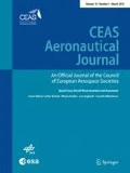
Reference [6] also emphasised that upset/LOC accidents are not confined to one type of aircraft operation, e.g., transport, they occur across the fleet, e.g., general aviation, military. Furthermore, LOC-I accidents were reported as “not a problem of yesteryear”, which is highlighted in Boeing’s commercial accident statistics shown in Fig. 5 [9].Footnote 1 Lambregts et al.’s analysis of the statistics highlighted the need for research to identify the root causes of this problem. Not unexpectedly, stall was subsequently reported as the main causal factor leading to LOC-I accidents (see Fig. 6). Based on their analysis, the need for new regulations and training programmes was reported to improve flight safety. This required a coordinated approach to address prevention of such upsets and associated recovery procedures.

Aviation accident occurrence categories 2009–2018 [9]

Numbers of LOC-I incidents and contributing factors
The need to develop new training requirements was also identified in the National Transportation Safety Board (NTSB) report on the 2009 Colgan Air accident. The report indicated that the probable cause of the accident was the captain's inappropriate response to the activation of the stick shaker. This led to an aerodynamic stall and a loss of control on approach from which the airplane did not recover [11]. Published in 2010, the NTSB report contained several recommendations including the need to: “Define and codify minimum simulator model fidelity requirements to support an expanded set of stall recovery training requirements, including recovery from stalls that are fully developed. These simulator fidelity requirements should address areas, such as angle-of-attack and sideslip angle ranges, motion cueing (authors’ emphasis added), proof-of-match with post-stall flight test data, and warnings to indicate when the simulator flight envelope has been exceeded”.
It should also be mentioned that, prior to recovery from a stall, the airplane pilot must recognise its presence, and be taught how to:
-
(a)
Be aware of threats that could cause the stall (environment, systems, pilot-induced).
-
(b)
Confirm the stall based on the available flight instrument readings and
-
(c)
Apply the appropriate intervention as early as possible.
Essentially, this is the concept of Threat and Error Management training, which first teaches threat identification (e.g., weather, time pressure, distractions, operational hazards), and then assesses how well these are managed. This concept is mentioned because of the imperative to consider the entire training of the pilot or crew, and not only the quality of the Flight Simulation Training Device (FSTD).
The need to address LOC-I accidents for fixed-wing aircraft was a central theme for the Royal Aeronautical Society’s Flight Simulation Group (FSG) 2009 Spring Conference entitled: ‘Flight Simulation: Towards the Edge of the Envelope’ [12]; this initiative was also cited in the NTSB Colgan Air accident report.
Upset Prevention and Recovery Training (UPRT) was proposed as a major potential contributor to enhancing aviation safety, primarily since it would introduce measures to prevent upsets. The loss of Air France 447 [13] coincided with the start of the conference, a sobering reminder of the importance of the work to come. ICATEE [14] was formed during the FSG Conference to deliver a long-term strategy for reducing the rate of LOC-I accidents and incidents through enhanced UPRT [15]. A key factor in the success of the work was that the Committee consisted of more than 80 members drawn from manufacturers, airlines, national aviation authorities and safety boards, simulator manufacturers, training providers, research institutions, academia and the pilot community.
ICATEE analysed the causes of LOC-I and created two work streams. The Training and Regulations Stream addressed the development of a UPRT requirements matrix, whilst the Research and Technology Stream performed a thorough analysis of the technological requirements for UPRT [15]. The Research and Technology stream reported that enhanced flight dynamics models representing post-stall behaviour and icing effects were lacking. Key conclusions and recommendations from the ICATEE work were as follows:
-
New initiatives required an integrated approach across the fixed-wing community including manufacturers, airlines, national aviation authorities and safety boards, simulator manufacturers, training providers, research institutions and pilot representatives,
-
For awareness and recognition (i.e., “prevention” training), current simulators without modification could be utilized if used in a more meaningful and proper manner,
-
Type-representative models are suitable for recovery training from stalls. Models do not need to be exact per aircraft type, but need to support the training objectives,
-
The development and maintenance of applicable aeronautical knowledge should complement simulator training, to improve pilots’ awareness of the fundamentals of aerodynamics, stall, cockpit indications and human factors,
-
Enhancements require validation by Subject Matter Experts and pilots, who must be properly qualified to assess the enhancements,
-
Clear articulation of the training benefit enhancements that can be derived from a range of training media.
Above all, international standards and civil aviation regulations would have to be adjusted to accommodate the new UPRT requirements (training, licensing and FSTDs).
The impact of the ICATEE work was that their recommendations resulted in a new ICAO Document 10011, “Manual on Aeroplane Upset Prevention and Recovery Training” [16]. National Aviation Authority regulations have also been impacted, with UPRT becoming a mandatory part of European civil-airline training programmes from December 2019 [17], and the Federal Aviation Authority (FAA) requiring all Part 121 airline pilots to be UPRT-trained by March 31st 2020 [18]. LOC-I prevention and UPRT feature strongly in the European Plan for Aviation Safety (EPAS) [19], with several Rule Making Tasks listed to improve safety by engaging key stakeholders, e.g., pilots, instructors, examiners, airline training organisations and operators. To ensure that the fixed-wing simulator qualification processes keep in line with the new training programmes, specifically related to UPRT, it has been acknowledged that updates to the simulator standards are required [20], reflecting the need for a more dynamic and data-driven approach to standards development. For example, to provide ‘useful’ vestibular cues to a pilot requires tuning of the motion platform. Objective motion cueing criteria have been developed [21] and implemented into fixed-wing simulators in response to the need for improved motion cueing in UPRT programmes.
2.1 Lessons learned from the fixed-wing UPRT programme
In terms of applying the lessons learned from the ICATEE work to rotary-wing LOC-I safety activities, there are a range of transferable items that would benefit any new rotorcraft safety initiatives; examples include:
-
Adopting the approach suggested by Harris and ICATEE to conduct a thorough review of causal factors, related to both accidents and current training practices and needs, would be an important first step to define future activities.
-
Examining and updating the definition of LOC-I as conducted by ICATEE; a similar statement is required for rotorcraft.
-
Identifying similar LOC-I contributing factors, e.g., pilot distraction or ineffective pilot monitoring. This could be addressed by developing skills for improved recognition and awareness of these events, especially when working as part of a crew. Through exposure to the potential confusion of upsets, UPRT assists pilots in developing reliable mental models of how they, and the aircraft, are oriented in space; adopting this approach would also benefit rotary-wing pilots.
-
Training exercises are learnt by rote and hence pilots have an expectation of what is to occur during the session. Exposing them to a different scenario so that they can experience the ‘startle’ factor could aid them in managing stressful events in the future. Landman et al. [22] have investigated this training problem and shown that pilots who were not presented with “highly scripted” scenarios were more likely to apply the correct skills than pilots who were trained in those scenarios.
-
ICATEE required a coordinated effort, not just in terms of stakeholders, but also in the media used to deliver the training.
One of the most significant ICATEE findings, based on an analysis of several LOC-I accident reports from safety investigation boards, was that pilots often do not recognise the airplane angle of attack or understand the aircraft’s energy, both of which must be managed to prevent an upset. Energy management is particularly important during the approach to landing. At flight speeds below minimum power there is a risk that the aircraft could enter a speed-unstable condition, exacerbated by incorrect control actions by pilots. Examples in the recent past are the crashes of Asiana Flt 214 [Boeing 777, Ref. 23] and CHC G-WNSB [AS332, Ref. 24]. In both cases, the crew’s mismanagement of the aircraft speed and flight path led to entry into irrecoverable conditions. Reference [25] describes the theory underlying such speed instability at low speed, providing aeronautical science training material for pilots to strengthen their competency. Understanding the threats and applying competencies to mitigate those threats is paramount. One of the competencies defined by ICAO is “Flight Path Management – Manual Control” [26], which includes monitoring and maintaining the desired flight path, and controlling the aircraft within the normal envelope. It is, however, important to understand that the pilot must utilise all competencies to maintain an acceptable level of safety throughout the flight. The competencies developed by airline pilots also generally apply to rotorcraft operations. These are:
-
1.
Knowledge.
-
2.
Application of procedures.
-
3.
Flight path management—manual control.
-
4.
Flight management—guidance and automation.
-
5.
Leadership and teamwork.
-
6.
Problem solving and decision making.
-
7.
Workload management.
-
8.
Situation awareness.
-
9.
Communication.
The composition of these within the rotorcraft environment will differ slightly. An obvious example occurs in single-pilot operations. which are not permitted in commercial CS-25 certified fixed-wing operations, where “Leadership and Teamwork” may not apply.
ICATEE recommended making greater use of flight simulators to develop the knowledge and skills related to prevention of upsets, rather than teaching rote responses to developed upsets, as had been trained in the past. Moreover, UPRT should become a training opportunity rather than a pilot testing programme.
As a result, the ICATEE team determined that 56% of the new training programme could be developed with existing Level D simulators combined with academic lessons [15]. To achieve further benefit from the use of simulators would require flight-model enhancements to better represent the physics, e.g., post-stall behaviour. A similar approach could be adopted for rotary-wing applications, namely, establishing the main causal factors and conducting a task analysis to identify gaps in current flight models that need to be addressed.
Whilst ICATEE focussed on upset prevention, the Simulation of Upset Recovery in Aviation (SUPRA) project examined the model and cueing fidelity requirements for fixed-wing post-stall recovery [27, 28]. The research indicated that whilst the pilots involved in the testing reported that the post-stall flight modelling was “representative” of their real-world experience, the majority implemented an incorrect recovery technique fixating on addressing any wing drop instead of prioritising angle of attack reduction. Intervention of the instructors was required to enhance the pilots’ basic knowledge of and reactions to stall recovery, reinforcing the ICATEE findings. A key finding of the SUPRA work was that provision of ‘appropriate’ vestibular cueing was an important part of the training; a topic we return to later in the paper.
Another addition to FSTDs, that supports UPRT, is the ability for the instructor to know that the training is taking place within validated bounds of the flight model. During some manoeuvres, the pilot may bring the simulator close to the edge of the validated flight envelope. This information should be known by the instructor to enable them to judge the realism of the exercises being conducted and to prevent negative training transfer. UPRT was initially developed and implemented into aviation training regulations to address deficiencies in pilot skills and knowledge regarding upset recognition, prevention and recovery. Industry concluded that these shortcomings contribute to LOC-I incidents and accidents. Now that initial UPRT has been completed by most airlines, UPRT is becoming an ongoing practice and part of regular training to maintain pilot competencies. Accordingly, it has been proposed by industry that competency-based training, as well as the creation of training scenarios derived from lessons learned related to real-world events (Evidence-Based Training) can provide a realistic and applicable context to pilot skills maintenance. A similar methodology could be adopted in helicopter training simulators.
From the fixed-wing UPRT initiative, it is clear that a coordinated activity was required across the training, regulation and research communities to identify the main causal factors for LOC-I accidents and the process for mitigation using simulation; these lessons-learned can be applied in the rotorcraft community.
3 Challenge areas for rotorcraft LOC-I modelling and simulation
Drawing on the experience and approach used by the ICATEE team, key questions have been identified to inform the requirements for future LOC-I modelling and simulation activities. The following sections will draw on these questions, highlighting gaps that need addressing in current practices and opportunities that are available to support new rotorcraft safety initiatives. The questions are:
-
Q1.
What are the main causal factors that contribute to helicopter LOC-I?
-
Q2.
What human factors issues play a role in these accidents?
-
Q3.
Which pilot competencies are involved that fail in these accidents?
-
Q4.
How can helicopter pilot competencies be better trained?
-
Q5.
What are the requirements for better training methods, scenarios and tools?
-
Q6.
How can any missing physics from simulation models be identified to enhance models that are fit for purpose?
-
Q7.
What are the simulator cueing requirements to support LOC-I training?
-
Q8.
What are the fidelity requirements for predictive (i.e., flight model) and perceptual (i.e., overall simulation) fidelity for LOC-I training simulators?
-
Q9.
What benefits do alternative training and simulation tools offer, e.g., virtual or augmented reality?
3.1 Rotary-wing safety initiatives
The IHST activity (2005–2016), to reduce the worldwide helicopter accident rate, contributed to a reduction in accident rates from 4.61 to 3.49 per 100,000 h with the fatal accident rate reducing from 1.4 to 0.61 per 100,000 h (it should be noted that gathering ‘accurate’ number of flight hours is difficult and the values quoted are best estimates). The initial ISHST studies catalysed further analysis of the causes of rotorcraft accidents (Q1), identifying that LOC-I was a factor in 41% of the accidents analysed.
The USJHAT proposed a range of intervention recommendations (IRs) (see Fig. 7) to reduce accident rates [29], including the following training (T) related IRs:
-
T1060—simulator training—basic manoeuvres, develop and implement a standard for pilot training focusing on operational-specific scenarios, human factors (Q2), and the use of simulators and flight training devices (FTDs) (Q5)
-
T2060—simulator training—advanced manoeuvres (Q4). Incorporate simulators into training programmes that would include dynamic rollover, emergency procedures training (Q3), ground resonance, quick stop manoeuvres, targeting approach procedures and practice in approaches to pinnacle, unimproved landing areas, and elevated platforms
-
T6019—training emphasis for maintaining awareness of cues critical to safe flight (Q3). Establish training programmes that train and evaluate proficiency of critical issues, such as systems failures, impending weather concerns, effects of density altitude, and wind and surface conditions that can become critical to safe flight.

Top IRs from the USJHAT [29]. (Note: percentages are not to sum to 100% as each accident was assigned multiple intervention recommendations)
The USHST undertook an analysis of 104 fatal helicopter accidents (2009–2013) to help identify the main common occurrence categories [30] (Q1). Using the CAST/ICAO Common Taxonomy Team (CICTT) occurrence categories, the three main categories contributing to half of the fatal accidents in that period were: LOC-I, defined as loss of aircraft control or deviation from intended flightpath whilst in-flight, Unintended Flight in Instrument Meteorological Conditions (UIMC) and Low-Altitude (LALT) Operations (Fig. 8).

Pareto chart of U.S. civil helicopter fatal accident data (2009–2013) [31]
In 2016, the US Helicopter Safety Team (USHST, formed in 2013 as a regional partner with IHST), adopted a new goal of achieving a 20% reduction in the US fatal helicopter accident rate by 2020, equating to 0.61 fatal accidents per 100,000 flight hours. The average fatal accident rate for the period 2015–2019 was 0.65, and the latest goal is to reduce the 5-year average fatal accident rate to 0.55 by 2025 [28].
This analysis of the accidents led to the identification of intervention strategies that could be implemented through Helicopter Safety Enhancement (H-SE) activities to tackle the underlying causal factors (Q1–7). Each H-SE identifies the organisations or groups who will implement the activity, a statement of the work required (informed by details of relevant accidents) and expected outputs; two simulator related activities were cited.
Starting in October 2019, H-SE 81, “Improve Simulator Modeling for Outside-the-Envelope Flight Conditions” was established to “improve the accuracy of full flight simulators (FFS)/flight training devices by providing recommendations for developing better mathematical physics-based models (authors’ emphasis added) for helicopter flight dynamics” (Q6). The goal is to “achieve more realistic, higher fidelity simulations of outside-the-envelope flight conditions” and to examine the “possible use of simulation for purposes of preventing, recognizing, and recovering from spatial disorientation” (Q8).
H-SE 127A, “Training for Recognition/Recovery of Spatial Disorientation” aims to “develop training for recognition of spatial disorientation (SD) and recovery to controlled flight.” It is acknowledged in this H-SE that the helicopter community should promote the wider use of available SD simulation technology and training scenarios (Q5) to create further awareness of impairment from SD and how to recover from such an event. Commencing January 2019, a review of current training documents and practices is underway to identify areas, where training can be enhanced [32].
The need for the wider use of flight simulators to prepare helicopter pilots for emergencies and improve safety is also acknowledged by the NTSB, in their 2015 Safety Announcement, “Safety Through Helicopter Simulators” [33], where they note, “it is difficult to recreate the element of surprise and the realistic, complex scenarios that pilots may experience during an emergency. Without simulators, viable lesson components may be limited”; a theme also noted in the ICATEE work. The challenge here is to develop simulators (Q7) and scenarios (Q5) to support this training. What is not included in the Safety Announcement are the necessary simulation fidelity requirements to conduct such training.
Effective pilot training can be developed when the issues and causal factors related to rotary-wing LOC-I are understood and defined. The European Helicopter Safety Analysis Team (EHSAT), in their accident review [6] (Q1) supporting the IHST initiative, reported that “pilot judgment and actions, and situational awareness” (Q3) were two of the most common contributors to accidents; reinforcing IHST’s findings.
EHSAT, a sub-group of the European Helicopter Safety Team (EHEST), conducted reviews of two sets of accident data, 2000–2005 and 2006–2010. In this latter period, some national teams were not able to analyse their results, so only 30% of the 527 accidents that occurred were included in the analysis. The output of the data analysis was not presented in the same manner as the USHST’s work, making direct comparisons of the causal factors difficult. Figure 9 shows the standard problem statements (SPS) Level 1 that were reported in the two periods. In the IHST taxonomy of the 14 main factors contributing to an accident, Level 1 identifies the main area of the problem, e.g., safety management, pilot judgement and actions. Pilot judgment featured in almost 70% of all accidents analysed and situation awareness in more than 33%.

Percentage of analysed accidents, where SPS Level 1 was assigned at least once [6]
Whilst Fig. 9 provides some insight into causal factors, it does not present those specifically related to LOC-I. Further investigation of what leads pilots to lose situational awareness and/or impact judgement and action is needed, together with an examination of the conditions they take place in (Q2 and Q3). This could be related, for example, to startle, spatial disorientation, improper instrument monitoring or fatigue. Adopting the ICATEE approach to understanding these underlying human factors issues should facilitate better problem identification and define competencies and methods to manage these problems as part of improved training programmes.
In Ref. [6], various IRs were reported to address the above (see Fig. 10) and the results were aimed at informing the content of the rotorcraft section of the EPAS document [19]. A training/instructional IR was listed as one of the leading IRs, although how to conduct this is not described and the need for supporting research was not recommended as a key IR; the need for supporting research is examined Sects. 4 and 5.

Number of IRs Level 1—all accidents 2000–2010 [6]
As part of the instructional IRs, EHEST has produced a variety of material to raise awareness of safety issues in the rotorcraft community. Reference [34], addressing “Training and Testing of Emergency and Abnormal Procedures in Helicopters”, shows that a significant number of helicopter accidents occur during the training or testing of emergency and abnormal procedures (EAP). The leaflet aims to provide guidance to instructors and examiners to deliver EAP in flight more safely. For Upset/Unusual Attitude Training, it is recommended that it should be conducted in good visual meteorological conditions with the candidate’s visibility limited by screens or goggles. This type of training, according to one former instructor [35], has hardly changed in 30 years and it is not clear how ‘more of the same’ will impact the LOC-I problem. In the fixed-wing UPRT development, the introduction of “failures” to enhance pilot situation awareness and teach better orientation was highlighted as an area for improvement. These may not necessarily be system failures, but instead “blanking out” certain portions of the outside world and/or instrument displays to query the pilot on their situation at that time.
More recently in Europe, the Rotorcraft Safety Roadmap [7] indicates that to achieve its vision of a 50% reduction in accidents by 2028, improved decision-making training to prevent, for example, inadvertent entry into Instrument Meteorological Conditions and Aircraft Upset/ LOC-I are required and that flight simulators need to be more widely used throughout the training cycle (Q5).
However, simply reproducing accidents or events leading to them would have limited effectiveness, since it is not feasible to train every such event. In addition, this approach does not develop pilot resilience to unknown factors (Q3 and Q5). Instead, understanding how the management of threats and errors might have failed, and which competencies were particularly weak during events, allows the training designer to develop more robust requirements. From these training requirements, the corresponding flight simulation functionality and fidelity requirements can be postulated (Q8).
Re-visiting the fixed-wing UPRT story, it should be noted that few fixed-wing aircraft have a direct indication of the wing angle of attack, including the critical (or stall) angle of attack. Nonetheless, there are multiple indicators, e.g., onset of buffet, lack of control responsiveness, which can be used to determine the safety margin that could trigger the firing of the stall warning alert. Teaching aeronautical science, and helping pilots to understand these concepts, as well as developing enhanced situation awareness with respect to angle of attack, was considered paramount. This is because most LOC-I accidents have been associated with stall (Fig. 6), which is an “angle-of-attack problem”. Similar training strategies, reinforcing aeronautical science and safety margins, can be introduced in rotorcraft flight training, for example, to develop a better understanding of situational awareness (4 and Q5).
The EPAS document identifies the need to address offshore helicopter LOC-I accidents as a strategic priority. There have already been significant initiatives in the offshore helicopter community to improve safety. The UK Civil Aviation Authority, together with the European Union Aviation Safety Authority (EASA) and the Norwegian Civil Aviation Authority, initiated an offshore safety review in 2013. The review made 29 recommendations under the themes of: “Passenger Safety and Survivability, Operations, Airworthiness and Improving Knowledge and Facilitating Change” [36]. Many of the recommendations have led to new working groups to continually review safety through the Offshore Helicopter Safety Action Group. HeliOffshore has also published a global safety strategy document [37] identifying priority areas for enhancing safety, including mitigating and preventing aircraft upsets. Although research has been conducted relating to offshore safety, e.g., to improve alerting in Helicopter Terrain Awareness and Warning Systems [38], no specific research initiatives have been recommended to help reduce LOC-I offshore accidents. Furthermore, in the EASA research agenda, Sect. 2.4 “Rotorcraft”, [39], there are no research activities relating to LOC-I aimed at the reduction of accident rates. The research agenda does highlight the need to think “out of the box”, to look at how training with new device platforms, e.g., virtual reality (Q9), could be used to provide innovation for FSTD qualification, but it does not deal with specific training needs. The challenge of using new technologies, and how regulations might need to be more flexible to allow their uptake, was one of the themes of the Royal Aeronautical Society’s 2019 Spring Flight Simulation conference [40] and should also be considered in any new LOC-I initiatives (Q9). Developing appropriate training requirements is, therefore, considered the essential first step (Q3–Q5).
What is absent in these rotorcraft safety initiatives is a clear, coordinated strategy of how to use modelling and simulation in training aimed to reduce accidents, and the supporting research required to achieve this [41,42,43]. As the increased use of simulators has been recognised as an important part of a strategy to improve safety, questions arise regarding what level of fidelity is required to achieve a positive transfer of training and how might this be assessed? Central to the utility of a simulator for delivering effective training is confidence in the fidelity standards against which it has been qualified. Uncertainties in the validity of metrics contained in the standards could undermine the benefits of training devices. A review of previous modelling and simulation research follows in the next sections to identify shortcomings and where new contributions could be made to enhance existing standards.
4 Rotary-wing aircraft modelling and simulation research
One objective of this paper is to highlight the research required to inform new regulatory activities, serving to reduce the number of rotorcraft LOC-I accidents. Hence, past and current safety-related research needs to be acknowledged.
Rotorcraft flight simulators in Europe are qualified through CS-FSDT(H) [44] which defines the technical minimum requirements/standards for each level of qualification (or type). Within CS-FSTD(H), the following qualification level types are listed:
-
Flight and Navigational Procedures Trainer I, II, III (FNPT).
-
Flight Training Device 1, 2, 3 (FTD).
-
Full Flight Simulator A, B, C, D (FFS).
Table 1 indicates the training value and credits that can be derived using the different types of flight simulators as part of an approved training programme [44]. The main market for this training is the commercial aviation sector. Reference [45] states that to comply with Private Pilot Licensing (PPL) requirements, trainees should have completed at least 45 h of flight instruction, five of which can be completed in FSTDs. It also notes, given that safety analyses point to General Aviation being a significant contributor to the high number of accidents, FSTDs should be more widely used for PPL(H) training, echoing the USHST’s recommendations (Q5).
CS-FSTD(H) defines the fidelity metrics and criteria that need to be satisfied with the certification of a flight simulator for crew training. From a safety perspective, these criteria should be robust and unambiguous. Several studies have been conducted to examine the validity of the CS-STD(H) tolerances and criteria; an overview of this research is provided here (Q8).
The Group for Aeronautical Research and Technology in Europe (GARTEUR) Action Group (AG) HC-AG12 was formed to conduct a critical examination of the simulator standard, JAR-STD 1H [46], (replaced by EASA CS-FSTD(H) in 2012), including correlation with handling qualities metrics and fidelity metrics [47,48,49]. The work revealed a range of shortcomings and opportunities to enhance the standards with new metrics. For example, the AG showed that the relationship between fidelity and the JAR-STD 1H metric tolerances is sensitive to the nature of the manoeuvre being flown and, more significantly, that matching tolerances does not always lead to matching handling qualities (Q8). AG12 also identified the need to bridge the gap between pilot subjective opinion and the quantified metrics, and the importance of developing an objective means for assessing overall fidelity.
In the previous section, using flight simulators to train for emergency situations was highlighted as an important approach for improving safety. In AG12, such a case was considered—One Engine Inoperative (OEI) landings, and the suitability of the CS tolerances was examined. The FAA and EASA regulations [50, 51] for emergencies require that, for Category-A certification (multi-engine helicopters), an aircraft should be able to continue its flight with OEI. In the case of an engine failure occurring after the helicopter has passed the landing decision point, the pilot must continue the landing. A four degree-of-freedom helicopter model (including horizontal body velocity, rate of descent, pitch rate and rotor rotational speed) was developed to examine the sensitivity of CS tolerances on a continuous landing procedure following an engine failure. The CS tolerances for this simulation case are given in Table 2 (note these are a subset of CS-FSTD(H) HQ validation tolerances).
Three test cases were developed in this study to determine the effect of applying CS tolerances to the simulation model throughout the manoeuvre:
-
A reference case: no tolerances were applied to the flight dynamics model.
-
Upper limit case: 20 ft in height, − 3 knots in velocity, 1.5% in pitch attitude and 10% in collective.
-
Lower limit case: − 20 ft in height, 3 knots in velocity, − 1.5% in pitch attitude and − 10% in collective.
A pilot model was included in the different test cases to control the energy stored in the rotor during the manoeuvre [49]. The resulting trajectories are shown in Fig. 11. A safe landing region was defined, where the touchdown was within acceptable velocity limits, namely, vertical velocity (wh) less than 1.5 m/s and horizontal velocity (uh) less than 4.5 m/s. The allowable tolerance ranges produce a landing scatter of 200/ − 90 m from the reference case and moves the landing velocities outside of the safe region. From a safety point of view, this variation could lead to a negative transfer of training giving the trainee an incorrect understanding of the performance of the helicopter in an emergency.

Helicopter landing footprint with simulation tolerances limits [47]
Research to address the AG12 recommendations to develop a method for the subjective assessment of simulator fidelity and the formulation of new objective metrics is reported in Refs. [52, 53]. The simulator fidelity rating (SFR) scale (see Appendix 1) was developed to provide a method for an evaluating pilot to rate the suitability of the overall simulation for a specified task [52] (Q8). The pilot is asked to compare the level of performance attained in flight and simulator, and to judge the level of ‘adaptation’ of task control strategy used in flight compared with simulation. New objective fidelity metrics [53] were also developed in the AG-12 follow-on research, based on ADS-33E-PRF HQ parameters [54] (Q8).
The methodologies developed were used to investigate an objective criterion that is ill-defined in CS-FSTD(H), related to a flight-model’s off-axis response [55]. CS-FSTD(H) states that, following a longitudinal input, the on-axis response of the simulation data should be within either ± 10% of the achieved peak in the flight data, or ± 3°/s, whichever is less restrictive, and the off-axis model response should be of “correct trend and magnitude” (CT&M) when compared to flight data. Figure 12 shows the on- and off-axis responses of a FLIGHTLAB Bell 412 (F-B412) simulation model [55] (configured with a Rate–Command–Attitude–Hold (RCAH) system) following a 0.5-in longitudinal input. Additional roll/pitch cross-couplings were implemented in FLIGHTLAB [56] by directing a proportion (20%, 50% and 100%) of the longitudinal control input into the roll axis. The off-axis responses exhibit the correct trend and so questions arise as to whether the magnitudes are “correct” and what effect the difference would have on a pilot’s experience of the simulation?

On- and off-axis rate responses to a longitudinal cyclic input for cross-coupling variations [55]
One way to assess the effect of the additional cross couplings is to use the inter-axis coupling criteria in ADS-33E-PRF [54]. This is defined, in this case, as the ratio of peak off-axis roll attitude response (∆ϕpk) from trim, within 4 s, to the on-axis pitch attitude response from trim at 4 s, (Δθ4), following a longitudinal control step input. As additional cross-coupling is increased in the model the HQs degrade from Level 1 for the baseline (no addition cross-coupling) to Level 3, with the expectation that the fidelity’ of the model would be compromised (see Fig. 13).

Model configurations using ADS-33E-PRF roll/pitch coupling requirements for aggressive agility [55]
This was assessed subjectively using the SFR scale for an ADS-33E-PRF acceleration–deceleration manoeuvre. Pilots trained in the baseline configuration and then, following a model change, awarded an SFR based on their comparison with the baseline. The results in Fig. 14 show that, as the cross-coupling increases, the SFRs awarded degrade from Level 1 to Level 3. This is indicative of a significant change in performance and considerable adaptation of task strategy (see Appendix 1). An additional cross-coupling of 20% produced a mean SFR that was on the Level 1–2 boundary indicating that, based on their subjective opinion, this would represent the boundary of an acceptable level of CT&M. Whilst these results are not comprehensive, they do show that a combination of new objective metrics and subjective assessments can be used to investigate revisions to the CS standards.

SFRs awarded for cross-coupling tests [55]
The AG12 authors recommended the “need to establish a firmer and more substantial relationship between simulation fidelity criteria and handling qualities criteria”. Whilst Refs. [53, 55] suggested that tolerances for HQ “fidelity metrics” based on objective and subjective assessments could be developed to define fidelity ‘levels’ of a model, especially in areas that are not covered in the CS, e.g., inter-axis coupling and frequency domain parameters, such as bandwidth and phase delay, further research is required to develop this approach (Q8).
To satisfy the proof-of-match tolerances for a Level D flight simulator, modifying or tuning the parameters of the flight model using either a physical or non-physical process is permitted. System IDentification (SID) [57] has been applied as an effective approach for informing this tuning process (Q6). A non-physical tuning approach has been developed and reported in Ref. [58], using SID techniques to optimise simulation parameters that may not be known with certainty, e.g., rotor blade stiffness, fuselage inertias, to meet the flight simulator standards proof-of-match requirements. This approach satisfies the Level D requirements but does not necessarily capture any missing physics which may be important in, for example, LOC-I simulations.
In Ref. [59], SID was used to explore the fidelity of existing rotorcraft simulation models and to produce a rational, physics-based approach to simulation fidelity improvement through model renovation. The renovation process involves augmenting the nonlinear flight model based on differences between stability and control derivatives identified from flight test (FT) data and the nonlinear (Nlr) flight model. Figure 15 illustrates the fidelity improvement of the renovated (reno.) nonlinear FLIGHTLAB Bell412 (Nlr F-B412) model in the roll, pitch and yaw axes for a 2311 input at 95 kts. Identification and renovation of non-physical modelling parameters in the simulation models are key to improving model fidelity, especially in dynamic manoeuvres.

Comparison of responses from lateral cyclic input with the renovated nonlinear F-B412 [59]
The above renovation method is to some extent limited due to the procedure relying on linear information extracted from the SID approach, and the tuning process for repairing the deficiencies in the fidelity of a model (Q6). These limitations can put constraints on its application, especially where nonlinearities and hereditary effects can influence the model’s response, such as in edge-of-the-envelope and out-of-the-envelope flight regimes, where current flight models are likely to be inaccurate. These deficiencies may lead to unrealistic training of manoeuvres involving, e.g., loss of tail rotor effectiveness (LTRE), vortex ring state (VRS), and rapid entry into autorotation; topics noted for further research in the H-SE activities.
The NTSB investigated 55 accidents involving LTRE during the 10-year period from 2004 to 2014 [60]. The results revealed that the pilots were unable to recover when the helicopters encountered unanticipated yaw suffered from the LTRE. More recently, the ‘mythical’ properties of unanticipated yaw and the LTRE ‘problem’ have been discussed in Ref. [61]; the Airbus author emphasising the importance of transferring improved understanding of the phenomena to pilots (Q5). More effective pilot training can help to reduce these accidents and enhanced simulator fidelity enables an increase in simulator/flight ratio in training. This is generally true, of course, but has particular value for high-risk LOC-I simulations.
More recent model-update research [62] has proposed a new identification approach in the time-domain, Additive System-IDentification (ASID), to address the nonlinearities associated with complex manoeuvres, particularly at low speed (Q6). This is described in more detail in Ref. [63]. In the ASID approach the model parameters are identified sequentially based on their contribution to the local dynamic response of the system, i.e., over a defined time range. One or more candidate parameters, in a proposed model structure, are identified using the primary response characteristic of the rotorcraft; others are then identified in a sequential manner.
The results in Fig. 16 illustrate the effectiveness of the ASID approach, comparing a 2311 input in hover FT data and the linear perturbation (Pert.) method. ASID was applied on the 6 degree of freedom roll dynamics, using an equation-error process. The roll acceleration ASID \(\dot{p}\) curves in Fig. 16 was constructed using the identified derivative values (e.g., rolling moment due to roll rate, Lp) derived from the corresponding flight test data (e.g., roll rate p), respectively.

Comparison of fit across perturbation and ASID approaches [63]
Figure 16 shows the best fit with flight test data is achieved by the ASID method. The fit with linear perturbation derivatives from the F-B412 diverges after 1.5 s, mainly due to Lq being significantly different from flight test. These results demonstrate the effectiveness of ASID at estimating derivatives that give an improved fit. Combining the results from different manoeuvres in a renovation process offers the potential for capturing a fuller range of physical effects that may be important, but only weakly present in simpler manoeuvres (Q6). This has particular relevance to the large amplitude excursions and accelerations during LOC-I situations.
Questions arise as to what is adequate fidelity to support training in rotorcraft LOC-I scenarios, not only prevention, but also inadvertent entry into such conditions and associated recovery strategies. Achieving anything close to physical realism, even generically, is considered a major challenge by the authors of this paper. Any type-specific characteristics will likely demand extensive development. Compared with fixed-wing stall, rotorcraft LOC-I scenarios are likely to pose a higher risk to life due to the nature of rotorcraft dynamics and require considerably more complex modelling. Referring to Q6 in Sect. 3, addressing these challenges will certainly require further theoretical and experimental research into the underlying aeromechanics of, for example, VRS and LTRE, and creating sufficiently realistic real-time flight models to incorporate in training simulators. The flight models produce the motions, the accelerations, velocities and positions, which are transferred to the pilot as visual and vestibular cues. In LOC-I scenarios the vestibular motion cueing might be crucial to aid the pilot in identification of the problem. Fidelity issues relating to vestibular motion is the topic of the next section.
5 Vestibular motion cueing research
In 1910, Flight magazine [64] reported, “Even the most apt pupil is certain to find himself in difficulties at some time or another during his probation… The Invention, therefore, of a device which will enable the novice to obtain a clear conception of the workings of an aeroplane and conditions existent in the air without any risk personally or otherwise is to be welcomed without doubt. Several have already been constructed to this end, and the Sanders Teacher is the latest to enter the field.” The Sanders Teacher (Fig. 17) featured aircraft parts (a ‘first’ in simulators) and a turn-table and rocker system that allowed the trainee to experience the effect of wind in the simulator; the first step in ‘motion cueing’ (and by this we are considering vestibular motion cueing), and its benefit in simulator-based training is still being debated.

Sanders teacher [64]
One of the challenges in this debate is the lack of supporting evidence concerning the benefit of motion cueing and how these might impact simulator certification standards. More than 20 years ago Burki-Cohen et al. [65] noted, “The existing standards for flight simulation qualification, all of which entail a requirement for platform motion cueing, have a 20-year record of meeting the requisite requirement for transfer of performance. In the absence of competing evidence to the contrary, it is, therefore, prudent to maintain these standards in the interest of public safety” (Q7). In a subsequent paper, Longridge et al. [66] reported that, for fixed-wing aircraft, motion improved the acceptability of the simulator, pilot performance and control behaviour in the simulator, but found no evidence of the benefits of motion in transferring to the aircraft. McCauley [67], investigated the need for motion bases in army helicopter simulators and found that whilst flight simulators were identified as “unquestionably valuable for training safely”, no evidence to support the effectiveness of motion platforms for training was found.
When examining the current standards, there is no clear guidance on when motion is required for a given training task. As shown in Table 3, there are different motion hardware requirements for the FSTD levels shown (e.g., A/B and C/D) but no rationale is provided for the validity of these criteria and no guidance is provided as to how motion drive algorithms should be tuned to maximise the motion envelope available for different rotorcraft/manoeuvres. In addition, there are no fidelity tolerances provided for the roll, pitch or sway motion envelopes and there is no linking of the motion envelope requirements shown in Table 3 to the flight-loop model parameters that are inputs to the motion drive laws, e.g., aircraft accelerations (Q8). Reference [68] suggests that this lack of acceleration proof-of-match requirements has led to deficiencies in simulator motion cueing especially in hover and low-speed flight conditions. For the ‘lower’ level FTD devices, there is no requirement for motion, since these are mainly intended for teaching aircraft systems and procedures knowledge and skills.
Another potential ‘conflict’ between matching the flight-loop fidelity tolerances and provision of motion cueing was noted by Casolaro et al. [69]. They reported achieving a match with simulator certification tolerances for the Dutch roll frequency and damping of a Super Puma Mk1 simulation. When assessed in Visual Meteorological Conditions, the pilots “concluded that the simulator was handling like the real helicopter”. However, despite no changes to the flight model, the pilots complained that the model was “too unstable and too difficult to manage” under Instrument Meteorological Conditions. Additional damping of the flight-model’s Dutch roll characteristics was implemented to satisfy the pilot’s subjective assessment of the fidelity of the model. The authors of Ref. [69] suggest that “distorted accelerations provided by the motion system and the delay introduced by the visual system” might be sources of the fidelity deficiency reported by the pilots. This reinforces the need to harmonise all elements of the fidelity assessment (most notably the flight model and motion cueing system) to ensure a rationale and repeatable fidelity assessment process is adopted.
Motion fidelity criteria for rotorcraft have been proposed by Sinacori [70] based on measures of the gain and phase shift between the flight-model output and the motion system commands at a frequency of 1rad/s. The criteria were developed from investigations of an ‘S’-turn manoeuvre along a runway at 60 kts with a six-degree-of-freedom model of a helicopter. Figure 18 shows Sinacori’s fidelity criteria for translational motion and the three-point fidelity rating scale used to elicit pilot opinion on the fidelity of the motion cues. It should be noted that Sinacori stated these criteria “have little or no support other than intuition”.

Sinacori’s translational motion fidelity criteria [70]
Despite this statement, Sinacori’s criteria have been the basis for motion fidelity testing. Hodge et al. [71] reviewed research undertaken for roll-sway motion tuning. Figure 19 shows the results from this review. The different gains and break frequencies used in the studies are shown in parenthesis, suggesting that high fidelity motion can be achieved, based on Sinacori’s criteria, through selective tuning of the motion filter parameters.

Sinacori’s rotational fidelity criteria [72]
Hodge et al. [72] used a short-stroke hexapod simulator [73] to investigate ‘optimising’ the cues with third-order filters in the roll and sway axes (A1–A6 in Fig. 19 indicate the configurations tested in [72]). A 10-point motion fidelity rating scale was devised to elicit pilot opinion, since the participating test pilots considered the previous three-point scale to be too coarse to distinguish the subtle differences in motion cues [74].
Pilots judged that good motion cues could be obtained with a small motion platform by careful selection of the roll and sway-axis motion gains (Kϕ, Ky) and that roll-axis break frequency (ωhpϕ) had a dominant effect on motion fidelity (see Fig. 20). The pilots also reported that at higher break frequencies they experienced an increased mis-match between the vestibular and visual motion cues. Lowering the roll gain ‘masks’ this effect by reducing the amplitude of the motion, making this mismatch less obvious, which could explain why the more favourable MFR ratings are concentrated at lower motion gains.

Effect of roll motion gain and break frequency on motion fidelity [72]
Whilst there have been several studies examining the effect of motion on single or limited axis tasks, there is still the need to examine the motion requirements for multi-axis tasks, considering aircraft with different levels of handling qualities undergoing a range of different dynamic manoeuvres. Manso et al. [75] conducted simulator experiments that examined the effect of motion cueing on task performance and workload for a range of test manoeuvres. Three test pilots flew three rotorcraft response types—Attitude Command Attitude Hold (ACAH), RCAH and bare airframe; covering a wide range of handling qualities. The ADS-33E-PRF test manoeuvres (bob-up, pirouette, precision hover, lateral reposition and accel/decel) were flown with different levels of task aggressiveness. A comparison was made for each manoeuvre between testing with no motion and a motion case, with a subjectively tuned set of motion drive laws. For the precision hover task, the results indicate that, as the HQs degrade, there is a larger difference in the HQ ratings (HQRs) awarded for the no-motion versus motion cases (Fig. 21), [75]. The lack of vestibular feedback in the no-motion cases affected the pilot’s ability to detect the onset of any vehicle drift preventing desired positional performance standards from being achieved.

HQR (upper) and SFR (lower) results for the precision hover task
The SFR scale was used to compare motion and no-motion cases with the pilots ‘training’ in the motion case (assuming this reflects the real-world case) and then assessing the effect of no-motion (i.e., testing in a fixed-based simulator) on the test manoeuvre. The assumption here is that, in lieu of being able to conduct a flight test, the motion case is representative of the real world and the assessment is examining the utility of training without motion. The pilots awarded poorer SFRs as the HQs degraded and comments indicated that they were lacking feedback from the motion platform which led to a degradation in task performance and required considerable task strategy adaptation. The results suggest that simulator motion fidelity requirements are not only task-based but are also dependent on the handling qualities of the aircraft being flown. Both are, of course, closely linked to the levels of control activity demanded to accomplish a given task.
Task orientation is recognised as important in the handling qualities community. Changing the focus of simulator standards to be more training-task led was made in the development of ICAO 9625, initially for fixed-wing aircraft and subsequently expanded to rotorcraft [76], which attempted to establish the simulation fidelity levels required to support the range of training tasks carried out for different pilot licenses and ratings. Reference [76] recognizes the need for training specific features and fidelity requirements. Each simulation feature, e.g., cockpit layout, flight model, has a required level of fidelity, e.g., generic, representative and specific or none, if the feature is not required, for a given training task. Whilst it does not provide any new fidelity tolerances, Ref. [76] does include details of an objective motion cueing test (OMCT), which measures the performance of the complete motion system, including the motion drive algorithm [21]. In Ref. [21], it was noted that OMCT was developed from the assessment of fixed-wing simulators and further work is required to examine requirements for rotorcraft. This need was confirmed by Jones et al. [77] who examined the suitability of OMCT criteria for a rotorcraft pirouette, lateral reposition and a pursuit tracking task. Motion fidelity ratings awarded by the pilots were not in agreement with the OMCT boundaries emphasising the need for research into defining rotorcraft-specific OMCT boundaries. A similar recommendation was made by Dalmeijer et al. [78] who noted that whilst the OMCT requirements for heave motion were satisfactory for the rotorcraft tasks flown (precision hover and take-off and abort), they were not appropriate for the pitch and surge motion characteristics in these manoeuvres.
In light of current OMCT limitations for application to rotorcraft, Miletovic et al. [79] have developed an Eigenmode Distortion Method to attempt to address the previously identified gap in the CS linking the simulated vehicle’s response to the design of the motion drive algorithms. This method represents a first attempt to objectively link the vehicle’s dynamics to the design of motion drive algorithms and warrants further development.
A challenge in discerning the utility of motion cueing in flight simulators from the published literature is that results are presented for different simulators, with different capabilities, simulating different tasks, whilst using different flight models. As noted by Grant [80], experiments are rarely repeated before trying to extend the work using new methods. Hence, if the new study contradicts any previous work it is often unclear if this is due to a different simulator or test protocol being used. It is anticipated that understanding the possible contributions of vestibular motion cueing to the simulation of LOC-I will require a more coordinated approach to help inform future simulator and regulatory requirements.
Research to date on both motion cueing and flight-model fidelity has pointed to potential improvements that could be made to both operational flight simulators and associated training programmes. Building on this will establish new, higher, levels of confidence in the value of flight simulators for crew training.
6 Concluding remarks and recommendations
An examination of rotorcraft accident statistics has shown that, despite the concerted international efforts to reduce the accident numbers and rates, it is likely to be some time before significant reductions are achieved.
LOC-I events feature significantly in the accident statistics. Several initiatives have been launched to address this problem and some have been discussed in the paper but referring to Qs 1–5 in Sect. 3, further investigation is required here. The USHST, through its H-SE activities, are investigating these issues and the output from these activities needs to be disseminated to the wider community.
When faced with a similar problem in the fixed-wing aircraft community, a coordinated international activity was established to develop the UPRT programme to tackle the problem. Some elements of UPRT can be transferred to rotorcraft training, such as including startle in scenarios, (aeronautical science) education to develop skills for better awareness and recognition and, most importantly, more effective use of flight simulators to support the overall training needs.
To improve flight models for use in LOC-I training, an assessment of current CS standards should first be undertaken to identify, where new fidelity criteria/tolerances are required (Q6–Q8). This needs to be supported by activities to understand flight-model shortcomings. Several initiatives related to this have been launched, but they would benefit from being extended to a wider international community as was the case with ICATEE. Improvements in rotorcraft modelling should be physics-based and research is needed here to inform the development of new standards and fidelity improvement methods. The system identification ‘renovation’ approach outlined in this paper provides a means for identifying model shortcomings and potential sources of deficiency.
In general, the simulation requirements must be driven by clear specifications of the training needs, related to the task, and including the definition of competencies that tend to fail prior to and during accident scenarios, and how to train these competencies in helicopter operations.
Understanding the simulation fidelity requirements for different levels of training device will be an important aspect of future LOC-I training. It is anticipated that different levels of LOC-I training could be conducted using a range of simulator types. This could include the use of desktop simulators and maturing technologies, such as virtual reality (see Q9).
The role of motion cueing in LOC-I training should be carefully examined. Whilst valuable research has been undertaken to examine how motion tuning can change the task performance achieved by pilots in different scenarios and devices, a consolidated approach using common fidelity metrics and methods should be developed. Without this, it would be difficult to provide the supporting evidence needed in any new standards as to how vestibular cueing should be provided in simulators.
The absence of fidelity requirements and standards for LOC-I simulation training points to the need for new research activity with planned outputs focussed on these aspects. Q6–Q8 in Sect. 3 identified the possible need for new research initiatives in this area and this has been reinforced by the activities reported in Sects. 4 and 5; some excellent work has been undertaken but more is required to address the issues Harris first highlighted in 2006 (Q1).
Driven by the need to improve rotorcraft safety, it is recommended that a programme similar to that adopted by the fixed-wing community is established with workshops focusing on, for example, training needs, modelling and simulation challenges, regulatory issues and other topics that need to be tackled to advance the state of the art in this area. Whilst some of this is currently being undertaken by the USHST, a more co-ordinated international effort between the regulators, operators and researchers is recommended.
Notes
Note: Only the top 6 causes have been included for clarity of figure.
Abbreviations
- δ lat :
-
Pilot lateral cyclic control displacement (inches)
- Δϕ pk :
-
Peak roll axis attitude change from trim (°)
- Δθ 4 :
-
Pitch attitude response from trim at 4 s (°)
- ω hp ϕ :
-
Roll-axis break frequency (rad/s)
- h :
-
Vertical position (m)
- p, q, r :
-
Angular velocity components of helicopter about fuselage x-, y-, z-axes (°/s)
- \(\dot{p}\) :
-
Roll acceleration (°/s2)
- u h :
-
Horizontal touchdown velocity (m/s)
- v, w :
-
Translational velocity components of the helicopter along the fuselage y-, z-axes (m/s)
- w h :
-
Vertical touchdown velocity (m/s)
- x :
-
Horizontal position (m)
- K ϕ, K y :
-
Roll and sway motion gains (–)
- L q :
-
Rolling moment due to pitch rate (1/s)
- ACAH:
-
Attitude Command Attitude Hold
- AG:
-
Action Group
- CAST:
-
Commercial Aviation Safety Team
- CT&M:
-
Correct Trend and Magnitude
- EAP:
-
Emergency and Abnormal Procedures
- EASA:
-
European Union Aviation Safety Authority
- EHEST:
-
European Helicopter Safety Team
- EHSAT:
-
European Helicopter Safety Analysis Team
- FAA:
-
Federal Aviation Authority
- FNPT:
-
Flight and Navigational Procedures Trainer
- FSS:
-
Full Flight Simulators
- FSG:
-
Flight Simulation Group
- FSTD:
-
Flight Simulation Training Device
- FTD:
-
Flight Training Devices
- GARTEUR:
-
Group for Aeronautical Research and Technology in Europe
- HQ:
-
Handling Qualities
- H-SE:
-
Helicopter Safety Enhancement
- ICATEE:
-
International Committee for Aviation Training in Extended Envelopes
- IHST:
-
International Helicopter Safety Team
- IR:
-
Intervention Recommendations
- LOC-I:
-
Loss of Control In-Flight
- NTSB:
-
National Transportation Safety Board
- OEI:
-
One Engine Inoperative
- OMCT:
-
Objective Motion Cueing Test
- RCAH:
-
Rate–Command–Attitude–Hold
- SFR:
-
Simulator Fidelity Rating
- SPS:
-
Standard Problem Statements
- SUPRA:
-
Simulation of Upset Recovery in Aviation
- UIMC:
-
Unintended Flight in Instrument Meteorological Conditions
- UPRT:
-
Upset Prevention and Recovery Training
- USJHAT:
-
US Joint Helicopter Safety Analysis Team
- USHST:
-
US Helicopter Safety Team
References
Harris, F.D.: No accidents – that’s the objective, the 26th Alexander A. Nikolsky honorary lecture. J. Am. Helicopter Soc. 52(3), 3–14 (2007)
Harris, F.D., Kasper, E.F., Iseler, L.E.: U.S. civil rotorcraft accidents, 1963 through 1997, NASA TM-2000-209597
Padfield, G.D.: Rotorcraft handling qualities engineering: managing the tension between safety and performance, the 32nd Alexander A. Nikolsky honorary lecture. J. Am. Helicopter Soc. 58(1), 1–27 (2013)
http://www.ihst.org/portals/54/Key_Charts/2015%20USHST%20Metrics%203%20slides.pdf
U.S. Joint Helicopter Safety Analysis Team: the compendium report: the U.S. JHSAT baseline of helicopter accident analysis: volume I (2011)
Anon.: Analysis of 2006–2010 European helicopter accidents” EHSAT analysis report (2015)
Anon.: Rotorcraft Safety Roadmap, EASA (2018)
Lambregts, A.A., Nesemeier, G., Wilborn, J.E., Newman, R.L.: Airplane upsets: old problem, new issues. In: AIAA modeling and simulation technologies conference and exhibit, 18–21 Aug, Hawaii (2008)
Anon.: Statistical summary of commercial jet airplane accidents: worldwide operations 1959–2018, 50th edn. Boeing Commercial Airplane Group (2019)
Anon.: Final report on the investigation into the accident involving the Armavia A320 near Sochi Airport on 3 May 2006 Bureau d’Enquêtes et d’Analyses pour la sécurité de l’aviation civile – Paris, France (2007)
Anon.: Loss of control on Approach Colgan Air, Inc. Operating as continental connection flight 3407 Bombardier DHC-8-400, N200WQ Clarence Center, New York, Feb 12, 2009 NTSB Report Number: AAR-10-01 (2010)
Royal Aeronautical Society Conference: Flight simulation: towards the edge of the envelope, London, UK June 3–4 (2009)
Anon.: Final report on the accident on 1st June 2009 to the airbus A330-203 registered F-GZCP operated by Air France flight AF 447 Rio de Janeiro. Bureau d’Enquêtes et d’Analyses pour la sécurité de l’aviation civile – Paris, France (2012)
Advani, S.K., Schroeder, J.A.: Global implementation of upset prevention & recovery training. In: AIAA SciTech Forum, 4–8 Jan, San Diego, CA (2016)
Anon.: Manual on aeroplane upset prevention and recovery training. ICAO Doc. 10011 (2011)
Anon.: Commission Implementing Regulation (EU) 2018/1974 of 14 December 2018 amending regulation (EU) No 1178/2011 laying down technical requirements and administrative procedures related to civil aviation aircrew pursuant to Regulation (EU) 2018/1139 of the European Parliament and of the Council. European Commission (2018)
Anon.: Enhanced pilot training and qualification for title 14 of the code of federal regulations (14CFR) Part 121 Pilots. FAA (2017)
Anon.: European plan for aviation safety 2020–2024. EASA (2019)
Anon.: Update of flight simulation training device requirements - upset prevention and recovery training (CS-FSTD(A) - Issue 2). EASA (2018)
Advani, S., Hosman, R.: Design and evaluation of the objective motion cueing test and criterion. Aeronaut. J. 120(1227), 873–891 (2016)
Landman, A., Groen, E.L., van Paassen, M.M., Bronkhorst, A.W., Mulder, M.: Dealing with unexpected events on the flight deck: a conceptual model of startle and surprise. Hum. Factors 59(8), 1161–1172 (2017)
Anon.: Descent below visual glidepath and impact with seawall Asiana Airlines Flight 214 Boeing 777-200ER, HL7742 San Francisco, California July 6, 2013 NTSB/AAR-14/01 PB2014-105984 (2014)
Anon.: Report on the accident to AS332 L2 Super Puma helicopter, G-WNSB on approach to Sumburgh Airport on 23 August 2013, Air Accidents Investigation Branch, Aircraft Accident Report 1/2016 (2016)
Padfield, G.D.: Helicopter flight dynamics: including a treatment of tiltrotor aircraft, 3rd edn. Wiley, Hoboken (2018)
Anon.: Procedures for air navigation services - training - (Doc 9868), International Civil Aviation Organisation, 2nd edn (2016)
Ledegang, W.D., Groen, E.L.: Stall recovery in a centrifuge-based flight simulator with an extended aerodynamic model. Int. J. Aviat. Psychol. 25(2), 122–140 (2015)
Nooij, S.A.E., Wentink, M., Smaili, H., Zaichik, L., Groen, E.L.: Motion simulation of transport aircraft in extended envelopes: test pilot assessment. J. Guid. Control Dyn. 40(4), 776–788 (2017)
Anon.: The compendium report: the U.S. JHSAT baseline of helicopter accident analysis: volume II. U.S. Joint Helicopter Safety Analysis Team (2011)
Anon.: United States helicopter safety team charter V4 (2020)
Anon.: Report helicopter safety enhancements: loss of control inflight, unintended flight in IMC, and low-altitude operations. U.S. Helicopter Safety Team (2017)
Anon.: Helicopter safety enhancement (H-SE) 127A training for recognition/recovery of spatial disorientation, Rev 2 USHST (2019)
Anon.: Safety through helicopter simulators - use of simulators can prepare helicopter pilots for emergencies and prevent accidents. NTSB Safety Alert, SA-031 (2015)
Anon.: Training and testing of emergency and abnormal procedures in helicopters. European Helicopter Safety Team, Training Leaflet HE11(2015)
Private communication
Anon.: Safety review of offshore public transport helicopter operations in support of the exploitation of oil and gas. Progress report – 2016, UK Civil Aviation Authority, CAP 1386 (2016)
Anon.: Discussion paper on offshore helicopter strategy, HeliOffshore (2017)
Anon.: Class A HTAWS warning annunciation, UK Civil Aviation Authority CAP 1747 (2018)
Anon.: Agency research agenda 2019–2021. EASA REV version 30/10/2018 (2018)
Royal Aeronautical Society Flight Simulation Group Spring Conference on ‘The Future Reality of Flight Simulation’, 11–12 June, London, UK (2019)
White, M.D., Padfield, G.D., Lu, L., Advani, S.: Rotorcraft loss of control in-flight – the need for research to support increased fidelity in flight training devices, including analogies with upset recovery for fixed-wing aircraft. In: EASA safety workshop at the 44th European rotorcraft forum, 18–21 Sept, Delft, Netherlands (2018)
White, M.D., Padfield, G.D., Lu, L., Advani, S.: Flight training device fidelity requirements to address ‘rotorcraft loss of control inflight’. In: 75th Vertical Flight Society Forum, 13–16 May, Philadelphia, USA (2019)
White, M.D., Advani, S.: Rotorcraft loss of control in-flight: the need for research to support increased fidelity in flight training devices. In: The Royal Aeronautical Society’s Autumn Flight Simulation Conference, Rotorcraft Simulation – Trends and Future Applications, 12–13 Nov, London, UK (2019)
Anon.: Certification specifications for helicopter flight simulation training devices, CS-FSTD(H), EASA, Initial Issue (2012)
Anon.: Advantages of simulators (FSTDs) in helicopter flight training/European Helicopter Safety Team, Training Leaflet HE6 (2013)
Anon.: JAR-STD 1H, helicopter flight simulators. Joint Aviation Authorities (2001)
Padfield, G.D., Pavel, M., Casolaro, D., Roth, G., Hamers, M., Taghizad, A.: Validation criteria for helicopter real-time simulation models; sketches from the work of GARTEUR HC-AG12. In: 30th European Rotorcraft Forum, 14–16 Sept, Marseilles, France (2004)
Padfield, G.D., Pavel, M., Casolaro, D., Roth, G., Hamers, M., Taghizad, A.: Fidelity of helicopter real-time models. In: 61st Annual Forum of the American Helicopter Society, 1–3 June, Grapevine, Texas (2005)
Pavel, M.D., White, M.D., Padfield, G.D., Roth, G., Hamers, M., Taghizad, A.: Validation of mathematical models for helicopter flight simulators current and future challenges. Aeronaut. J. 117(1190), 343–388 (2013)
Anon.: AC-29A, certification of transport category rotorcraft. federal aviation administration advisory circular (1987)
Anon.: Certification specifications and acceptable means of compliance for large rotorcraft CS-29, Amendment 7 EASA (2019)
Perfect, P., Timson, E., White, M.D., Padfield, G.D., Erdos, R., Gubbels, A.W.: A rating scale for the subjective assessment of simulation fidelity. Aeronaut. J. 118(1206), 953–974 (2014)
Perfect, P., White, M.D., Padfield, G.D., Gubbels, A.W.: Rotorcraft simulation fidelity: new methods for quantification and assessment. Aeronaut. J. 117(1189), 235–282 (2013)
Anon.: Handling qualities requirements for military rotorcraft. ADS-33E-PRF, US Army (2000)
Timson, E., Perfect, P., White, M.D., Padfield, G.D., Erdos, R.: Pilot sensitivity to flight model dynamics in flight simulation. In: 37th European Rotorcraft Forum, 13–5 September Gallarate, Italy (2011)
DuVal, R., He, C.: Validation of the FLIGHTLAB virtual engineering toolset. Aeronaut. J. 122(1250), 519–555 (2018)
Tischler, M.B., Remple, R.K.: Aircraft and rotorcraft system identification: engineering methods with flight test examples, 2nd edn. American Institute of Aeronautics and Astronautics, Reston (2012)
Spira, D., Myrand-Lapierre, V., Soucy, O.: Reducing blade element model configuration data requirements using system identification and optimization. In: 68th Annual Forum of the American Helicopter Society, May 1–3, Fort Worth, TX (2012)
Lu, L., Padfield, G.D., White, M.D., Perfect, P.: Fidelity enhancement of a rotorcraft simulation model through system identification. Aeronaut. J. 115(1170), 453–470 (2011)
Anon.: Loss of tail rotor effectiveness in helicopters, national transportation safety board, Safety Announcement SA-062 March (2017)
Dequin, A.-M.: The myth of losing tail rotor effectiveness. In: 45th European Rotorcraft Forum, Sept 17–20, Warsaw Poland (2019)
Cameron, N., White, M.D., Padfield, G.D., Lu, L., Agarwal, D., Gubbels, A.W.: Rotorcraft modeling renovation for improved fidelity. In: Vertical Flight Society 75th Annual Forum, 13–16 May, Philadelphia, USA (2019)
Flight Magazine, December 1006 (1910)
Burki-Cohen, J., Soja, N., Longridge, T.: Simulator platform motion – the need revisited. Int. J. Aviat. Psychol. 8(3), 293–317 (1998)
Longridge, T., Burki-Cohen, J., Go, T.H., Kendra, A.J.: Simulator fidelity considerations for training and evaluation of today’s airline pilots. In: Proceedings of the 11th Int. Symp. on Aviation Psych., 5–8 March, Columbus, OH (2001)
McCauley, M.E.: Do army helicopter training simulators need motion bases? United States Army Research Institute for the Behavioral and Social Sciences, Technical Report 1176 (2006)
Gates, N.: Driving rotary simulator effectiveness through improved standards. In: The Royal Aeronautical Society’s Autumn Flight Simulation Conference, Rotorcraft Simulation – Trends and Future Applications, 12–13 Nov, London, UK (2019)
Casolaro, D., Dequin, A.-M., Gaulene, P.: Eurocopter experience in flight loop development for level D training simulator. In: 30th European Rotorcraft Forum, 14–16 Sept, Marseilles, France (2004)
Sinacori, J.B.: The determination of some requirements for a helicopter flight research simulation facility, NASA-CR-152066 (1977)
Hodge, S., Manso, S., White, M.D.: Challenges in roll-sway motion cueing fidelity: a view from academia. In: Royal Aeronautical Society Flight Simulation Group Spring Conference on ‘Challenges in Flight Simulation’, 9–10 June, London, UK (2015)
Hodge, S.J., Perfect, P., Padfield, G.D., White, M.D.: Optimising the roll-sway motion cues available from a short stroke hexapod motion platform. Aeronaut. J. 119(1211), 23–44 (2015)
White, M.D., Perfect, P., Padfield, G.D., Gubbels, A.W., Berryman, A.C.: Acceptance testing and commissioning of a flight simulator for rotorcraft simulation fidelity research. Proc. Inst. Mech. Eng. Part G J. Aerosp. Eng. 227(4), 663–686 (2013)
Hodge, S.J., Perfect, P., Padfield, G.D., White, M.D.: Optimising the yaw motion cues available from a short stroke hexapod motion platform. Aeronaut. J. 119(1211), 1–22 (2015)
Manso, S., White, M.D., Hodge, S.: An investigation of task specific motion cues for rotorcraft simulators. In: AIAA Science and Technology Forum and Exposition 4–8 Jan, San Diego (2016)
Anon.: Manual of criteria for the qualification of flight simulation training devices - volume II — Helicopters. ICAO 9625 (2012)
Jones, M., White, M.D., Fell, T., Barnett, M.: Analysis of motion parameter variations for rotorcraft flight simulators. In: 73rd Annual Forum of the American Helicopter Society, May 9–11, Fort Worth, TX (2017)
Dalmeijer, W., Miletović, I., Stroosma, O., Pavel, M.D.: Extending the objective motion cueing test to measure rotorcraft simulator motion characteristics. In: 73rd Annual Forum of the American Helicopter Society, May 9–11, Fort Worth, TX (2017)
Miletović, I., Pavel, M.D., Stroosma, O., Pool, D.M., van Paassen, M.M., Wentink, M., Mulder, M.: Eigenmode distortion as a novel criterion for motion cueing fidelity in rotorcraft flight simulation. In: 44th European Rotorcraft Forum, 18–21 Sept, Delft, Netherlands (2018)
Grant, P.: Benchmarking simulators: results from a replicated helicopter yaw motion study. In: Royal Aeronautical Society Flight Simulation Group Spring Conference on ‘Striving for Effectiveness in Flight Simulation’, 13–14 June, London, UK (2017)
Acknowledgements
The current Rotorcraft Simulation Fidelity project is funded at the University of Liverpool and collaborators at Cranfield University by the UK’s EPSRC through grants: EP/P031277/1 and EP/P030009/1. Thanks also to our project partners Advanced Rotorcraft Technology Inc., AMRDEC, and the Flight Research Laboratory at the NRC, Ottawa. The role of test pilots in the Liverpool research has been crucial to informing our understanding of operational issues, particularly relating to LOC-I.
Author information
Authors and Affiliations
Corresponding author
Additional information
Publisher's Note
Springer Nature remains neutral with regard to jurisdictional claims in published maps and institutional affiliations.
Appendix 1: simulator fidelity rating scale (Ref. [50])
Appendix 1: simulator fidelity rating scale (Ref. [50])

Rights and permissions
Open Access This article is licensed under a Creative Commons Attribution 4.0 International License, which permits use, sharing, adaptation, distribution and reproduction in any medium or format, as long as you give appropriate credit to the original author(s) and the source, provide a link to the Creative Commons licence, and indicate if changes were made. The images or other third party material in this article are included in the article's Creative Commons licence, unless indicated otherwise in a credit line to the material. If material is not included in the article's Creative Commons licence and your intended use is not permitted by statutory regulation or exceeds the permitted use, you will need to obtain permission directly from the copyright holder. To view a copy of this licence, visit http://creativecommons.org/licenses/by/4.0/.
About this article

Cite this article
White, M.D., Padfield, G.D., Lu, L. et al. Review of flight simulation fidelity requirements to help reduce ‘rotorcraft loss of control in-flight’ accident rates. CEAS Aeronaut J 12, 701–721 (2021). https://doi.org/10.1007/s13272-021-00542-6
Received:
Revised:
Accepted:
Published:
Issue Date:
DOI: https://doi.org/10.1007/s13272-021-00542-6