
Abstract
The field of pipelined FFT hardware architectures has been studied during the last 50 years. This paper is a survey that includes the main advances in the field related to architectures for complex input data and power-of-two FFT sizes. Furthermore, the paper is intended to be educational, so that the reader can learn how the architectures work. Finally, the paper divides the architectures into serial and parallel. This classification puts together those architectures that are conceived for a similar purpose and, therefore, are comparable.
1 Introduction
The year 2020 marks 50 years since the first pipelined FFT hardware architectures were presented in 1970 [44, 68]. During these 50 years, the field of fast Fourier transform (FFT) hardware architectures has developed substantially. By deepening in the field, we have been able to understand the mathematical fundamentals that govern the architectures and this has allowed us to derive efficient circuits to calculate the FFT.
The aim of this paper is to collect the main advances in pipelined FFT hardware architectures so far, and present them in a way that the reader can understand how the architectures work, serving as an introduction to the field. The paper focuses on pipelined FFT architectures for power-of-two sizes and complex input data. Other types of architectures such as iterative and fully parallel FFTs, real-valued FFTs, variable-length architectures, FFTs for natural input/output order and non-power-of-two FFT sizes are outside the scope of this paper. Likewise, the paper targets the architectures themselves and the advances in other sub-fields related to them [36] are not considered. Therefore, advances related to FFT algorithms, data management in FFTs, implementation of rotators and accuracy analysis are not studied in detail in this paper. Only some concepts in these sub-fields are provided in Sections 2 and 6, as they are necessary for understanding the architectures. Further information related to these sub-fields can be found in [40].
The paper is organized as follows. After discussing some basic concepts in Section 2, an overview of pipelined FFT hardware architectures is provided in Section 3. This overview introduces the types of pipelined FFT architectures and includes a chronology with the main advances in the field. Later, the different types of pipelined FFT architectures are described in Sections 4 and 5. Section 4 is devoted to serial FFT architectures, whereas parallel FFT architectures are discussed in Section 5. For a better understanding of the architectures, a brief discussion on rotations in FFT architectures is provided in Section 6. A comparison of the architectures is provided in Section 7. Finally, the main conclusions of the paper are summarized in Section 8.
2 The FFT Algorithm
The N-point discrete Fourier transform (DFT) of an input sequence x[n] is defined as:
where X[k] is the output at frequency k, and \(W_{N}^{nk} = e^{-j\frac {2\pi }{N}nk}\) are called twiddle factors.
The term FFT refers to a group of efficient algorithms to calculate the DFT. Among them, the most widely used algorithm was proposed by Cooley and Tukey [19]. The Cooley-Tukey algorithm reduces the number of operations from \(\mathcal {O}(N^{2})\) for the DFT to \(\mathcal {O}(N \log _{2}{N})\) for the FFT. This is achieved because the calculation of the outputs X[k] in the DFT includes operations that are shared among the outputs.
2.1 Flow Graph and Radix
FFT algorithms are generally represented by their flow graphs. Figure 1 shows the flow graph of a 16-point radix-2 FFT, decomposed according to the decimation in frequency (DIF) decomposition [27, 40]. The FFT consists of \(n=\log _{2} N\) stages. At each stage of the graph, s ∈{1,…,n}, butterflies and rotations are calculated.
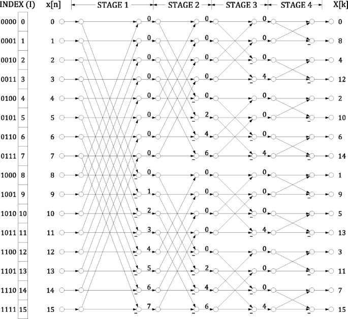
Flow graph of a 16-point radix-2 DIF FFT.
The numbers at the input of the flow graph represent the index of the input sequence, whereas those at the output are the frequencies, k, of the output signal X[k]. Finally, each number, ϕ, in between the stages indicates a rotation by
As a consequence, data for which ϕ = 0 do not need to be rotated. Likewise, if ϕ ∈ [0,N/4,N/2,3N/4], data must be rotated by 0∘, 270∘, 180∘ and 90∘, which correspond to complex multiplications by 1, − j, − 1 and j, respectively. These rotations are considered to be trivial, because they can be calculated by interchanging the real and imaginary components and/or changing the sign of the data.
Figure 1 also includes an index I with its binary representation bn− 1…b1b0. This index will be used to understand the architectures. Indeed, at each stage s, the bit bn−s plays a crucial role in the architecture, which will be explained in Section 2.2.
Figure 2 shows the flow graph of a 16-point radix-2 FFT decomposed according to decimation in time (DIT). It can be noted that DIF and DIT decompositions only differ in the rotations at the FFT stages. Indeed, it was observed in [27] that FFT algorithms for powers of two FFT sizes and based on the Cooley-Tukey algorithms only differ in the rotations at the different stages. This means that the structure of butterflies is the same for all the algorithms.

Flow graph of a 16-point radix-2 DIT FFT.
The DIF and DIT radix-2 FFT algorithms were the first ones based on the Cooley-Tukey algorithm. Later, other radices were proposed. All the radices have the form ρk. On the one hand, the base of the radix, ρ, indicates the size of the butterflies. Radices with base ρ = 2 use radix-2 butterflies as the basic structure, as shown in Figure 3. Radices with base ρ = 4 use radix-4 butterflies as the basic structure, as shown in Figure 4. On the other hand, the exponent of the radix, k, refers to how the rotations are distributed among FFT stages, meaning that the most complex rotations are placed every k stages.

Radix-2 butterfly.

Radix-4 butterfly.
Figure 5 shows the flow graph of a 16-point radix-22 FFT. In radix-22 algorithms, odd stages in the flow graph only include trivial rotations, as can be observed in the figure. In FFT architectures, this will allow for simplifying the rotators of the architectures.

Flow graph of a 16-point radix-22 FFT.
Finally, higher radices such as radix-23, radix-24 and radix-25 offer different distributions of rotations at the FFT stages. Further information on FFT algorithms can be found in [27, 70].
2.2 The bit b n−s
The bit bn−s is the essence of FFT architectures. In order to understand its relevance, let us consider the flow graph in Figure 1. At the first stage, the butterflies operate on the pairs of data with indexes (0,8), (1,9), (2,10), etc. By representing these indices in binary, we get (0000,1000), (0001,1001), (0010,1010). The comparison of the indices in each pair shows that each pair only differs in the most significant bit, which is b3, and this holds for all the pairs of indices at stage 1. By doing the same analysis for stage 2, we can see that the indices of pairs of data that are processed by the butterflies only differ in b2. For stage 3 it is b1 and for stage 4 it is b0.
In general, for any N-point FFT with \(n= \log _{2} N\) stages, pairs of data that are processed together in the butterflies at stage s differ in bn−s. This is an important statement that leads to the following one: In any FFT architecture, pairs of data that are input at a butterfly at the same clock cycle must always differ in the bit bn−s of the index. This guarantees that the architecture calculates the butterflies of the algorithm correctly. This will be the base for the explanation of the architectures in Sections 4 and 5.
3 Overview of Pipelined FFT Architectures
Figure 6 shows the general structure of a pipelined FFT. It consists of n stages connected in series where data flows from stage 1 towards stage n, and each stage s of the architecture calculates all the computations of one stage of the FFT algorithm. Each stage has P inputs and P outputs, and data flow in continuous flow at a rate of P data per clock cycle.

Structure of a pipeline FFT architecture.
3.1 Types of Pipelined FFT Architectures
Table 1 shows a classification of pipelined FFT architectures. The table separates the architectures into serial and parallel. Serial pipelined FFT architectures process a continuous flow of one datum per clock cycle and will be studied in Section 4. They are classified into single-path delay feedback (SDF), single-path delay commutator (SDC), single-stream feedforward (SFF) and serial commutator (SC).
Parallel pipelined FFT architectures process P data per clock cycles, where P > 1, and will be studied in Section 5. They are classified into multi-path delay feedback (MDF), multi-path delay commutator (MDC) and multi-path serial commutator (MSC).
3.2 Chronology
Table 2 shows a timeline with the main advancements in the area of FFT hardware architectures. The table includes only those works that have proposed new types of architectures or relevant modifications that have lead to a reduction in the number of resources. Other papers in the field that provide relevant contributions but target already known architectures are not included in the chronology.
The first two pipelined FFT architectures where proposed in 1970 with a few months of difference. They were the first SDC FFT [68] and the first SDF FFT [44], both for radix-2. The first MDC FFTs were proposed in 1973 [42]. This work included alternatives for different radices. However, it had the limitation that the parallelization of the architectures must be equal to the radix, i.e., P = r. This way, radix-2 was used to process 2 data in parallel, radix-4 to process 4 data in parallel and radix-8 to process 8 data in parallel.
For SDF FFT architectures, the use of radix-4 was introduced in 1974 [23]. In 1979, an SDF FFT architecture that divided the calculation in FFTs of 16 points was presented [24]. Although it was referred to as a radix-16 algorithm, this architecture was what we call nowadays radix-24. For SDC FFT architectures radix-4 was adopted in 1989 [7].
An evolution of MDC FFT architectures happened in 1983 [50], where the first radix-2 FFT hardware architectures for any P were presented. This dissociated the number of parallel data from the radix. The number of parallel data did not have to be equal to the radix anymore.
MDF FFTs had a late appearance with respect to SDF, SDC and MDC architectures, as the first MDF FFTs were presented in 1984 [82].
Radix-22 was introduced in 1998 for SDF FFT architectures [45]. Radix-2 made a better use of the butterflies than radix-4, whereas radix-4 made a better use of the rotators than radix-2. From them, radix-22 took the best of both radix-2 and radix-4. This is why the literature started to talk about radix-2k since then.
However, there was still an issue with the usage of butterflies and rotators in FFT architectures, as no architecture so far achieved a 100% utilization of butterflies and rotators. This was solved in 2006 when a deep feedback SDF FFT was presented [85]. Nevertheless, this improvement came at the cost of and increase of 33% in memory.
From 1989 to 2008, SDF FFTs were the main serial FFT architectures. The reason was that SDC FFTs only reached 50% utilization, as they were not processing data during half of the time. This was solved in 2008, when an SDC FFT that split the higher and lower part of the data bits was presented [9]. This was followed by two works on SDC FFT architectures that split data into the real an imaginary components [65, 81]. These two works differed in the management of the rotators.
In the meantime, new advancements on MDC FFT architectures were presented. The first radix-22 MDC FFTs were introduced in 2009 [26], which was extended to radix-2k in 2013 [33].
In 2016, a new MDF FFT called M2DF was introduced [80]. This architecture was based on making a better use of the butterflies in MDF architectures.
The first SC FFT architecture was also presented in 2016 [35]. This was the first architecture to use circuits for serial-serial permutation, leading to 100% utilization in butterflies and rotators, while using a small memory.
The SFF FFT was presented in 2018 [47]. This serial architecture uses a small number of butterflies, rotators and multiplexers. This is achieved by making use of a double memory.
Finally, the first MSC FFT was presented in 2020 [46], which is the parallel version of the SC FFT.
4 Serial Pipelined FFT Architectures
4.1 The SDF FFT Architecture
Figure 7 shows a 16-point radix-2 SDF FFT architecture [1, 44]. Each stage includes a radix-2 butterfly (R2), a rotator (⊗) or trivial rotator (diamond-shaped), and a buffer of length L = 2n−s. The internal structure of a stage is shown in Figure 8 and the timing of one stage of the SDF FFT is shown in Figure 9.

16-point radix-2 SDF FFT architecture.

Stage of a radix-2 SDF FFT architecture. (a) Conventional drawing. (b) Alternative drawing.

Timing of a radix-2 SDF FFT architecture.
The SDF works in a simple way, which can be understood from Figures 8 and 9. At each stage, it receives the data in the flow graph in Figure 1 in the order of the index, i.e., from top to bottom in the flow graph. According to this order, pairs of data that differ in bn−s arrive with a difference of 2n−s clock cycles. In order to have these pairs of data simultaneously at the input of the butterfly, a buffer of length L = 2n−s is used. This way, the output of the buffer is computed in the butterfly together with the input of the stage. Afterwards, one of the results of the butterfly continues towards the multiplier and the other output is saved in the buffer. From Figure 8(b) it can be clearly seen that data do not change order and they simply pass through the butterfly at certain clock cycles. In Figure 9 the light blue rectangle indicates when the butterfly processes data, which occurs when part A is at the output of the buffer and part B at the input of the stage. This occurs 50% of the time. The other 50% of the time is used to allow data flow through the buffer. This results in a 50% utilization of the butterfly.
A radix-2 SDF FFT architecture uses one butterfly per stage, which corresponds to \(2 \log _{2} N\) complex adders for the entire FFT. It also includes non-trivial rotators in all the stages but the last two, leading a total number of \(\log _{2} N -2\) rotators. Finally, adding the buffer lengths at each stage s = {1,…,n} results in a total memory of N − 1.
The radix-4 SDF FFT architecture [23, 71] is shown in Figure 10. The number of stages in this case is \(n = \log _{4} N = \log _{4} 16 = 2\). Each stage uses a radix-4 butterfly and three buffers of length L = 4n−s. The internal structure of a stage in a radix-4 SDF FFT architecture is shown in Figure 11. The idea is the same as in the radix-2 FFT. However, in this case the butterfly processes four data that are equally separated in time. Figure 12 shows the timing. Here groups of data flow through the buffers and the butterfly is in use 25% of the time. This utilization is lower than that of radix-2. However, the reduction of stages in radix-4 reduces the number of rotators.

16-point radix-4 SDF FFT architecture.

Stage of a radix-4 SDF FFT architecture.

Timing of a radix-4 SDF FFT architecture.
The total number of complex adders in the butterflies of a radix-4 FFT is \(8 \log _{4} N\), the total number of rotators is \(\log _{4} N -1\) and the total memory is N − 1. As a result, radix-4 halves the rotator complexity with respect to radix-2 but doubles the butterfly complexity.
A 16-point radix-22 SDF FFT architecture [6, 20, 22, 43, 45, 55, 58, 67, 74, 79, 88,89,90] is shown in Figure 13. It works as a radix-2 SDF FFT, being the data management the same. The only difference is in the rotators, which can be observed by comparing Figures 1 and 5. As radix-22 only has trivial rotations in odd stages, the rotators in those stages are also trivial.

16-point radix-22 SDF FFT architecture.
As a result, a radix-22 SDF FFT has the same butterfly and memory complexity as radix-2 but half the complexity of the rotators, which is \(1/2 \cdot \log _{2} N -1\). This rotator complexity is the same as in radix-4. Therefore, radix-22 benefits from the small complexity of the butterflies in radix-2 and the small complexity of the rotators in radix-4.
Higher radices have also been considered for the SDF FFT architecture. The literature includes SDF FFT architectures for radix-23 [2, 52], radix-24 [24, 25, 51, 54, 66, 72], and split radix [86]. Indeed, several radices of the form 2k are considered in some works [21, 29, 77].
Despite the fact that high-radix SDF FFTs are very popular, they have a utilization of 50% for the butterflies. A way to improve this utilization is to use the deep feedback strategy in [85]. The deep feedback SDF FFT architecture is shown in Figure 14, the detail of a stage of the architecture is shown in Figure 15 and the timing in Figure 16. It can be noted that the stages include three buffers, one of them with double length than the other ones. First, data enter the long buffer, and then the other two buffers. The timing indicates when butterflies are calculated. They use a radix-2 butterfly that is reused at different time instants. Also, the input data to the butterfly is taken from different nodes of the circuit at different time instants. This is why the stage in Figure 15 uses multiplexers to route the data. Furthermore, there is no overlap between the calculations of the butterfly, and the radix-2 butterfly is in use 100% of the time.

16-point deep feedback radix-2 SDF FFT architecture.

Stage of a deep feedback radix-2 SDF FFT architecture.

Timing of a deep feedback radix-2 SDF FFT architecture.
The total number of complex adders in the butterflies of a deep feedback SDF FFT architecture is \(2 \log _{4} N\), the total number of rotators is \(\log _{4} N -1\) and the total memory is 4(N − 1)/3.
4.2 The SDC FFT Architecture
Although the SDC processes serial data, it is based on a 2-parallel MDC FFT, such as that in Figure 17. The timing for the MDC FFT architecture is shown in Figure 18, where the data order at each stage is indicated. For instance, stage 1 receives the data with indexes 0 and 8 in parallel, followed by 1 and 9 and so on. It can be noted that data that differ in bit bn−s arrive in parallel at the input of the butterflies, which allows for calculating the butterflies properly. However, the data order is not the same at each stage, which makes it necessary to include shuffling circuits to reorder the data. These circuits consist of two buffers and two multiplexers, where the number drawn in the buffer is the buffer length. The buffers at stage 1 exchange the position of data with indexes (7,6,5,4) and (11,10,9,8). This is done by delaying the lower path 4 clock cycles in the buffer, swapping both sets of data with the multiplexers and then delaying the upper path 4 clock cycles so that data are again aligned. The data exchanges done by the shuffling circuits are indicated in the timing with lines that connect the data sets and the resulting order is the order at the following stage.

16-point 2-parallel radix-2 MDC FFT architecture.

Timing of a 16-point 2-parallel radix-2 MDC FFT architecture.
The SDC FFT architecture [21, 68] is shown in Figure 19. The only difference with the MDC FFT in Figure 17 lies in the input and output of the data. Whereas the MDC receives two data in parallel at the input, the SDC receives data in series. The first half of the data passes through the input buffer and the second half is connected to the lower input. This creates the same order as in the timing of Figure 18. Afterwards, the architecture processes the data. Finally, the output is made serial again.

16-point radix-2 SDC FFT architecture.
The consequence of making data parallel is that the architecture only works 50% of the time, whereas the other 50% of the time it receives and outputs the data.
In terms of hardware components, the architecture in Figure 19 uses a total of \(2\log _{2} N\) complex adders in butterflies, \(\log _{2} N -2\) rotators and a total memory of 2N − 2.
To solve the low utilization of the SDC FFT in Figure 19, several alternatives have been proposed. The first one is shown in Figure 20 and was proposed in [9]. This architecture splits the high (H) and low (L) parts of the data in two branches. This way, the architecture is working 100% of the time. To achieve this, the architecture changes slightly with respect to the SDC in Figure 19. First, it includes pre-processing and post-processing stages. Furthermore, both upper and lower branches include multiplexers. Finally, the complexity of butterflies, rotators and buffers is reduced, as they receive half of the bits every clock cycle.

16-point radix-2 SDC FFT architecture that divides the data in high and low parts.
The timing for the architecture in Figure 20 is shown in Figure 21. The first two shuffling circuits are used to adapt the input order to the butterfly of stage 1. Note that the orders at the different stages fulfill the demand of bn−s. Finally, the shuffling circuit after the last stage places again the high and low bits of the data in parallel, which allows for concatenating them and form the output data.

Timing of a 16-point 2-parallel radix-2 SDC FFT architecture that divides the data in high and low parts.
For the SDC architecture in Figure 20, the number of complex adders in butterflies is \(2 \log _{2} N\). As the adders have half the data word length, the adder count results in \( \log _{2} N\). The number of rotators is \(\log _{2} N -2\) after the half word length correction. And the total memory is 3N/2 after the half word length correction.
An alternative to the architecture in Figure 20 consists in splitting the input data into its real and imaginary parts. This alternative was used in [10, 65]. In this case, the timing is the same, and the architecture only differs in the rotators. If we observe the timing in Figure 21 and assume that H corresponds to the real part (R) and L corresponds to the imaginary part (I), then each rotator receives the real and imaginary components of the same datum in consecutive clock cycles through the same branch. This allows for using the circuit in Figure 22 to place the real and imaginary components of the data in parallel at the input of the rotator. Then the rotation is calculated and, after that, the data order is restored.

Rotator in an SDC FFT architecture that divides the data in real and imaginary parts.
For this architecture, the complex adder count is \(\log _{2} N\), the rotator count is \(\log _{2} N-2\) and the total memory is slightly larger than 3N/2 due to the registers used to adapt the order at the rotators.
A further step in the evolution of SDC FFT architectures is shown in Figure 23 and corresponds to [81], where it is observed that the separation in R and I leads to the fact that only data through the lower branch of the architecture need to be rotated. This allows for using the rotator in Figure 24, which has half of the complexity, as the rotation is done in two consecutive clock cycles.

16-point radix-2 SDC FFT architecture that divides the data in real and imaginary parts.

Alternative rotator in an radix-2 SDC FFT architecture that divides the data in real and imaginary parts.
For this architecture, the complex adder count is \( \log _{2} N\), the rotator count is \(1/2 \cdot \log _{2} N -1\) and the total memory is 3N/2.
4.3 The SFF FFT Architecture
The SFF FFT shares with the SDF FFT the characteristic that data arrive in natural order at the input of the architecture. Indeed, the order at each stage in both architectures is from top to bottom of the flow graphs.
Figure 25 shows a 16-point radix-2 SFF FFT architecture and its timing is shown in Figure 26. A characteristic of the SFF FFT is that it calculates the addition and the subtraction of the butterfly at different time instants. This allows for using the same adder/subtractor for both of them. To achieve this, each stage needs two buffers of length L = 2n−s. This allows for accessing the data that are processed in the adder/subtractor twice, first from the input and the point in between the buffers in order to calculate the addition of the butterfly, and then from the point in between the buffers and the output of the second buffer in order to calculate the subtraction of the butterfly. This is shown in the timing of Figure 26.

16-point radix-2 SFF FFT architecture.

Timing of a radix-2 SFF FFT architecture.
The rotators in an SFF FFT are the same as in an SDF FFT. They receive data from a single stream in natural order. Therefore, the SFF allows for the same use of the radices as in an SDF FFT. For instance, radix-22 makes trivial the rotators in odd stages, which reduces the rotator complexity.
The complex adder count of an SFF FFT is \(\log _{2} N\), the number of non-trivial rotators is \(\log _{2} N -2\) for radix-2 and \(1/2 \cdot \log _{2} N -1\) for radix-22, and the total memory is 2N − 2.
4.4 The SC FFT architecture
Figure 27 shows a 16-point radix-2 serial commutator FFT [35]. As in other FFT architectures, the stages consist of butterflies, rotators and shuffling circuits. What makes the SC FFT different is that it uses circuits that shuffle data arriving in series [32]. The timing of a stage in the architecture is shown in Figure 28. At each stage of the SC FFT, data that differ in bit bn−s arrive in consecutive clock cycles. This allows for delaying half of the data one clock cycle to make values that differ in bit bn−s arrive simultaneously to the butterfly. After the calculations, the other half of the data is delayed one clock cycle to form the serial data flow again.

16-point radix-2 SC FFT architecture.

Timing of a radix-2 SC FFT architecture.
According to this, bn−s is related to consecutive clock cycles at stage s, and bn−s− 1 is related to consecutive clock cycles at stage s + 1. Therefore, the shuffling circuits placed between stages are used to adapt these orders.
The internal structure of a stage in an SC FFT is shown in Figure 29. As data flows serially, both the real and imaginary parts of the data are provided at the same clock cycle. These parts are separated at the input of the stage. Thanks to the shuffling at the input of the stage, the butterfly will first add and subtract the real parts of the data, and in the next clock cycle it will add and subtract the imaginary parts of the data. This way, the butterfly only requires one real adder and one real subtractor. Similarly, the rotator receives data to be processed in two consecutive clock cycles. This allows for halving the complexity of the rotator. Instead of four multipliers an adder and a subtractor, the rotator only needs two multipliers and one adder/subtractor.

Stage of an SC FFT architecture.
As a result, the SC FFT requires a total of \(\log _{2} N\) complex adders for the butterflies, \(1/2 \cdot \log _{2} N -1\) rotators and a memory slightly larger than N.
5 Parallel Pipelined FFT Architectures
5.1 The MDF FFT architecture
The MDF FFT architecture is the parallel version of the SDF FFT. At first, MDF FFT architectures consisted of several SDF FFT architecture connected by shuffling circuits [82]. However, it is even easier to unfold an SDF into an MDF. Let us compare the SDF FFT in Figure 7 to the MDF FFT in Figure 30. In the SDF FFT data arrive in series in natural order, i.e., from index 0 up to N − 1. In the MDF FFT the data order at all the stages is shown in Figure 31. In it, even-indexed data flow through the upper path and odd-indexed through the lower path. As a consequence, the last stage, which operates on b0 directly, takes the data from both paths. Likewise, by separating even-indexed and odd-indexed data, those data that differ in bn−s are closer in the pipeline, which halves the length of the buffers at stages 1 to n − 1. Except for these facts, the MDF FFT works as an SDF FFT.

16-point 2-parallel radix-2 MDF FFT architecture.

Timing of a 16-point 2-parallel radix-2 MDF FFT architecture.
A higher parallelization for the MDF FFT is also possible. Figure 32 shows the case of a 16-point 4-parallel radix-2 MDF FFT architecture, and Figure 33 shows its timing. Again, the first stages process data as in an SDF FFT and the length of the buffers in these stages is divided by P with respect to the buffer lengths in the SDF FFT. The last two stages process b1 and b0. Both of them appear in parallel streams, so it is only necessary to combine those parallel streams, which differ in the bit corresponding to each stage.

16-point 4-parallel radix-2 MDF FFT architecture.

Timing of a 16-point 4-parallel radix-2 MDF FFT architecture.
In general, a P-parallel radix-2 MDF FFT uses \(2P \log _{2} N - P \log _{2} P\) complex adders in butterflies, \(P \log _{2} N - P/2 \cdot \log _{2} P - P - [1]^{*}\) non-trivial rotators, where the term [1]∗ only applies for P = 2, and a total memory of N − P. As in SDF FFT architectures, radix-22 used in MDF FFTs transforms the rotators in odd stages to trivial rotators, which halves the rotator complexity.
The literature explores 2-parallel MDF FFTs for radix-22 [59] and radix-24 [57]. Regarding 4-parallel MDF FFTs, radix-4 [11], radix-23 [13, 62], radix-24 [16, 17, 63, 73] and radix-25 [75] have been considered. And for 8-parallel MDF FFTs, there exist designs that use radix-2 [24], radix-23 [64], radix-24 [12, 76] and radix-25 [15].
An alternative to the conventional MDF FFT architectures is the M2DF FFT shown in Figure 34 and presented in [80]. The M2DF FFT increases the utilization of the butterflies and rotators by creating two data flows in opposite directions. These two data flows do not overlap in time, which allows for sharing the butterflies and rotators and achieve a 100% utilization of these components. To guarantee that there is no overlap, one of the data flows needs to enter the pipeline in bit-reversed order [31]. This can be observed in Figure 34, where the lower input path is connected to a block that calculates the bit reversal (BR) before entering stage 3. The upper path flows from stage 1 to stage 3 and is connected to a bit reversal circuit after stage 3.

16-point 2-parallel radix-2 M2DF FFT architecture. The boxes labeled with BR are circuits to calculate the bit reversal [31].
The timing of the M2DF FFT is shown in Figure 35. The indices for the current FFT are highlighted in black and the previous and following FFTs in the pipeline are highlighted in gray. The upper flow is shown to the left and the lower flow to the right. The upper flow follows the stages 1, 2, 3, BR, and 4, whereas the lower flow follows the stages BR, 3, 2, 1, and 4. The clock cycles where butterflies and rotators process data are indicated by a square. For instance, for the upper dataflow the first 4 clock cycles data are loaded into the buffer, and the next 4 clock cycles are used to process these data together with the input data. By analyzing the timing, it can be observed that the processing times at stages 1 to 3 of both data flows do not overlap, which allows for reusing the hardware components. Finally, the data from both data flows arrive simultaneously at stage 4 to be processed in parallel.

Timing of a 16-point 2-parallel radix-2 M2DF FFT architecture.
The 2-parallel radix-2 M2DF FFT architecture uses \(2 \log _{2} N\) complex adders in butterflies, \(\log _{2} N -2\) non-trivial rotators and a total memory of approximately 2N. This memory is the result of adding the buffers at the FFT stages and the circuits for bit reversal, whose optimum implementation is explained in [31]. Higher parallelization for this architecture and other radices are also possible [80].
5.2 The MDC FFT Architecture
The MDC FFT architecture was explained in Section 4.2 for the case of 2-parallel data and radix-2. In this section, other MDC FFT architectures are presented.
Figure 36 shows a 16-point 4-parallel radix-2 MDC FFT architecture [50]. The timing of the architecture is shown in Figure 37. At each stage, the shuffling circuits place data that differ in bn−s at the input of the butterflies.

16-point 4-parallel radix-2 MDC FFT architecture.

Timing of a 16-point 4-parallel radix-2 MDC FFT architecture.
For 8-parallel data, Figure 38 shows a 16-point 8-parallel radix-2 MDC FFT. Compared to the 4-parallel MDC FFT in Figure 36, the 8-parallel MDC architecture does not have shuffling circuits at the two first stages. The reason for this is that bn−s at the first stages is achieved by reorganizing the parallel streams and there is not need to exchange data that arrive at different clock cycles. This can be observed in the timing of Figure 39.

16-point 8-parallel radix-2 MDC FFT architecture.

Timing of a 16-point 8-parallel radix-2 MDC FFT architecture.
The number of hardware components of a P-parallel radix-2 MDC FFT architectures is \( P \log _{2} N\) complex adders in butterflies, \(P/2 \cdot (\log _{2} N -2)\) non-trivial rotators, and a total memory of size N − P.
For radix-22, Figure 40 shows a 16-point 4-parallel radix-22 MDC FFT [26, 33], and Figure 41 shows its timing. Due to using radix-22, odd stages only need trivial rotators, which reduces the complexity of the rotators in the architecture.

16-point 4-parallel radix-22 MDC FFT architecture.

Timing of a 16-point 4-parallel radix-22 MDC FFT architecture.
For 8-parallel data, a 16-point radix-22 MDC FFT architecture is shown in Figure 42 and its timing is shown in Figure 43.

16-point 8-parallel radix-22 MDC FFT architecture.

Timing of a 16-point 8-parallel radix-22 MDC FFT architecture.
For a P-parallel radix-22 MDC FFT, the number of complex adders in butterflies is \(P \log _{2} N\), the number of non-trivial rotators is \(3P/8 \cdot (\log _{2} N -2)\) and the total memory is N − P.
The rotator complexity in MDC FFT architectures can be reduced even more by using higher radices, such as radix-23 or 24 [33] and by exploring other data orders that allocate the rotators in only some of the parallel branches [34, 38].
In the literature, multiple MDC FFT architectures have been proposed for different parallelization. For 2-parallel data, radix-2 [3, 42, 50, 61], radix-22 [26, 33, 56], radix-23 [5, 33] and radix-24 [33] have been studied. Architectures that process 4-parallel data consider radix-2 [50], radix-4 [14, 18, 60, 69, 71, 84], radix-22 [26, 28, 33], radix-23 [33] radix-24 [8, 33], and various radices 2k [34]. Finally, 8-parallel MDC FFTs use radix-2 [50], radix-4 [48], radix-8 [4, 42, 71, 83, 87], radix-22 [26, 33] radix-23 [33, 41], radix-24 [33], radix-25 [53], radix-26 [49], and various radices 2k [34].
5.3 The MSC FFT architecture
The MSC FFT is the parallel version of the SC FFT architecture. In order to obtain the MSC FFT, the SC FFT is unfolded. As a result, the MSC FFT consists of several stages that include an SC structure and other stages that are calculated as an MDC.
Figure 44 shows a 16-point 4-parallel radix-2 MSC FFT. Its timing diagram is shown in Figure 45. The architecture consists of four stages where the two first ones process data as in an SC FFT. For these two stages, samples that are processed together in the butterflies arrive in consecutive clock cycles, as happened for the SC FFT. Later, butterflies at stages 3 and 4 process data arriving at the same clock cycle at the inputs of the butterflies.

16-point 4-parallel radix-2 MSC FFT architecture.

Timing of a 16-point 4-parallel radix-2 MSC FFT architecture.
The number of components in an MSC FFT is calculated by considering that in the SC-like stages only half butterflies and half rotators are used. For a radix-2 MSC, this results in \(P\log _{2} N\) complex adders, \(P/2 \cdot (\log _{2} N- 2)\) non-trivial rotators and a total memory of size approximately equal to N − P.
In the literature, a combination of radix-23 and radix-24 has been used for a 128-point MSC FFT [46], which allows for a further reduction of the rotator complexity. However, due to the novelty of the MSC FFT architecture, research still needs to be done before drawing general conclusions about this type of architecture.
6 Rotations in FFT Architectures
To deepen into the topic of rotations in FFT architectures is outside the scope of this paper. However, for a better understanding of the FFT architectures, this section provides some basic ideas about rotations in FFTs.
First, it is worth mentioning how to obtain the rotation coefficients in FFT architectures. This can be done from the flow graph of the FFT and the timing diagram of the architecture. The timing diagram shows the data indexes (I) at any time and for every stage of the architecture, whereas the flow graph shows the rotations for each stage and index. Therefore, to determine the rotation coefficients of the FFT we just have to take each index from the timing diagram and obtain the corresponding rotation from the flow graph. As an example, let us consider the 4-parallel FFT architecture in Figure 36, its timing diagram in Figure 37 and its flow graph in Figure 1. At stage 2, data with indexes (12,13,14,15) flow through the lowest path of the architecture. This means that the rotator at this path of the architecture must rotate by the rotations corresponding to these indexes. By checking the flow graph in Figure 1, it can be observed that the rotations for indexes (12,13,14,15) at stage 2 are ϕ = (0,2,4,6). The exact coefficients are obtained from Eq. 2. For instance, for ϕ = 4,
This means that the rotator at the lowest path at the second stage of Figure 36 must rotate the datum with index 14 by − j.
When the FFT size is large, it is not easy to represent its flow graph. However, it is still possible to obtain the values for ϕ at each stage of the FFT flow graph mathematically. This is explained in [70] for any FFT algorithm that can be represented by a binary tree and more generally in [27] for any FFT algorithm that can be represented by a triangular matrix. For instance, for a radix-2 DIF FFT, ϕ is obtained as [27]
In particular, for stage s = 2 and N = 16,
Coming back to the example, the indexes I = (12,13, 14,15) in binary are b3b2b1b0 = (1100,1101,1110,1111). By applying (5), this results in the rotations ϕ = (0,2,4,6), which corresponds to the same values that were obtained from the flow graph.
The implementation of a rotator takes into account the angles that it must rotate at different clock cycles. If all the angles are trivial, the rotator will be a trivial rotator. Otherwise, the rotator will be more complex. When many different angles must be rotated, the rotator is called general rotator. General rotators are usually implemented by a complex multiplier or by the CORDIC algorithm [78]. When the number of different angles is small, it is feasible to implement the rotators as shift-and-add operations [39], which reduces their complexity.
Regarding the storage of rotations, for general rotators it is common to store all the coefficients in a read-only memory (ROM), although it is also possible to use memoryless CORDIC approaches [30] that do not require any memory. This is especially useful for large FFTs [51], where the coefficient memory would otherwise be large. For small rotators implemented as shift-and-add, it is also possible to generate the control signals for the rotator without storing them in a ROM [39].
Nowadays, existing FFT architectures already achieve the minimum number of adders, the smallest memory and the lowest latency. However, the amount and complexity of rotators in FFT architectures still need to be optimized. As a result, recent FFT architectures [34, 37, 38] focus on reducing the number of rotators and their complexity, which requires to study different data orders and obtain the best results among them in terms of rotators.
7 Comparison
Table 3 compares the different types of serial pipelined FFT architectures. The table includes the type of architectures, the hardware resources in terms of complex adders in butterflies, complex rotators and complex data memory, and the performance in terms of the latency and throughput of the architectures. For simplicity, \(n=\log _{2} N\) is used for reporting the number of adders and rotators.
SDF FFT architectures minimize the memory usage and the latency. Among them, radices 4, 22 and 24 also minimize the number of rotators. Conversely, the number of adders in SDF architectures is larger than in other architectures. The only exception is the deep feedback SDF FFT, which minimizes the number of adders at the cost of a larger memory.
Except for its first version, the SDC FFT minimize the number of adders. Its latest version also minimizes the number of rotators. However, SDC FFT architectures have higher memory usage and latency than other serial pipelined FFT architectures.
The SFF FFT minimizes the number of adders and the latency. Its radix-22 version also minimizes the number of rotators. The drawback is a larger data memory.
Finally, the SC FFT minimizes the number of adders and rotators, while achieving almost optimum memory usage and latency.
Table 4 compares the different types of parallel pipelined FFT architectures. The first column shows the type of architecture. The second, third and fourth columns show the number of adders, non-trivial rotators and data memory, respectively. The fifth columns shows the latency of the architectures and the sixth column shows the throughput.
The architectures in the table are classified according to their parallelization. For 2-parallel architectures M2DF, MDC and MSC architectures use the lowest number of adders and rotators. Additionally, MDC and MSC FFTs use a small memory. Regarding MDC FFTs, the use of an advanced radix such as radix-24 does not reduce the number of rotators with respect to radix-2. However, radix-24 reduces the complexity of the rotators with respect to radix-2, as it includes a larger number of W16 rotators instead of the larger rotators used in radix-2.
For 4-parallel architectures, M2DF, MDC and MSC FFTs achieve the smallest number of adders. The number of rotators in 4-parallel FFT architectures depends not only on the type of architecture, but also on the radix. The 4-parallel radix-22 MDC FFT architecture achieves the smallest number of rotators. However, the complexity of the rotators in the radix-24 MDC FFT is smaller. This fact is detailed in the comparison in [34]. Regarding data memory and latency, MDF, MDC and MSC FFT architectures require a small memory and have a low latency.
For 8-parallel architectures, M2DF, MDC and MSC FFTs achieve the smallest number of adders. The smallest number of rotators is achieved by the radix-23 MDC FFT architecture. MDF, MDC and MSC FFT architectures have a small data memory and achieve the lowest latency.
8 Conclusions
This survey paper has provided the main advancements on complex-input-data and power-of-two pipelined FFT hardware architectures during the last 50 years. The main types of serial FFT architectures are called SDF, SDC, SFF and SC. All of them process a continuous data flow of one sample per clock cycle. However, they follow different strategies to organize the data flow and do the calculations. This results in trade-off among adder, rotator and memory complexity. Regarding parallel FFT architectures, the main types are MDF, MDC and MSC, which are the parallel version of the SDF, SDC and SC FFTs, respectively.
References
Abdullah, S., Nam, H., McDermot, M., & Abraham, J. (2009). A high throughput FFT processor with no multipliers. In Proc. IEEE int. Conf. Comput. design (pp. 485–490).
Adiono, T., Irsyadi, M. S., & Hidayat, Y. S. (2009). Irawan, a.: 64-point fast efficient FFT architecture using radix-23 single path delay feedback. In Proc. Int. Conf. Electrical engineering informatics, (Vol. 02 pp. 654–658).
Ahmed, T. (2013). A low-power time-interleaved 128-point FFT for IEEE 802.15.3c standard. In Proc. Int. Conf. Informatics electron. vision (pp. pp. 1–5).
Ahmed, T., Garrido, M., & Gustafsson, O. (2011). A 512-point 8-parallel pipelined feedforward FFT for WPAN. In Proc. Asilomar conf. Signals syst. Comput. (pp. 981–984).
Ayinala, M., Brown, M., & Parhi, K. K. (2012). Pipelined parallel FFT, architectures via folding transformation. IEEE Trans. VLSI Syst., 20(6), 1068–1081.
Bansal, M, & Nakhate, S (2017). High speed pipelined 64-point FFT processor based on radix-22 for wireless LAN. In Proc. Int. Conf. Signal process. Integrated networks (pp. 607–612).
Bi, G., & Jones, E. (1989). A pipelined FFT processor for world-sequential data. IEEE Trans. Acoust., Speech Signal Processing, 37(12), 1982–1985.
Chan, C, Lin, H., & Liu, C. (2019). High-throughput 64k-point FFT processor for THz imaging radar system. In Proc. Int. Symp. VLSI design automation test (pp. 1–4).
Chang, Y. N. (2008). An efficient VLSI architecture for normal I/O order pipeline FFT design. IEEE Trans. Circuits Syst. II, 55(12), 1234–1238.
Chang, Y.N. (2012). Design of an 8192-point sequential I/O FFT chip. In Proc. World congress eng.comp. science, Vol. II.
Chang, Y.N., & Parhi, K.K. (2003). An efficient pipelined fft architecture. IEEE Trans. Circuits Syst. II, 50(6), 322–325.
Chen, Y., Lin, Y., Tsao, Y., & Lee, C. (2008). A 2.4-GSample/s DVFS FFT processor for MIMO OFDM communication systems. IEEE J. Solid-State Circuits, 43(5), 1260–1273.
Chen, Y., Tsao, Y. C., Lin, Y. W., Lin, C. H., & Lee, C. Y. (2008). An indexed-scaling pipelined FFT processor for OFDM-based WPAN applications. IEEE Trans. Circuits Syst. II, 55(2), 146–150.
Cheng, C., & Parhi, K.K. (2007). High-throughput VLSI architecture for FFT computation. IEEE Trans. Circuits Syst. II, 54(10), 863–867.
Cho, I., Patyk, T., Guevorkian, D., Takala, J., & Bhattacharyya, S. (2013). Pipelined FFT for wireless communications supporting 128–2048/1536-point transforms. In Proc. IEEE global conf. Signal inf. Process. (pp. 1242–1245).
Cho, S. I., & Kang, K. M. (2010). A low-complexity 128-point mixed-radix FFT, processor for MB-OFDM UWB systems. ETRI J., 32(1), 1–10.
Cho, S. I., Kang, K. M., & Choi, S.S. (2008). Implemention of 128-point fast Fourier transform processor for UWB systems. In Proc. Int. Wireless comm. Mobile comp. Conf. (pp. 210–213).
Choi, S., Govindu, G., Jang, J. W., & Prasanna, V. K. (2003). Energy-efficient and parameterized designs for fast Fourier transform on FPGAs. In Proc. IEEE int. Conf. Acoust. Speech signal process., (Vol. 2 pp. 521–524).
Cooley, J. W., & Tukey, J.W. (1965). An algorithm for the machine calculation of complex Fourier series. Mathematics of Computation, 19(90), 297–301.
Cortes, A., Sevillano, J.F., Velez, I., & Irizar, A. (2006). An FFT core for DVB-t/DVB-h receivers. In Proc. IEEE int. Conf. Electron. Circuits syst. (pp. 102–105).
Cortés, A., Vélez, I., & Sevillano, J.F. (2009). Radix rk FFTs: Matricial representation and SDC/SDF pipeline implementation. IEEE Trans. Signal Processing, 57 (7), 2824–2839.
Cuong, N. H., Lam, N. T., & Minh, N. D. (2012). Multiplier-less based architecture for variable-length FFT hardware implementation. In Proc. IEEE int. Conf. Comm. Electron. (pp. 489–494).
Despain, A.M. (1974). Fourier transform computers using CORDIC iterations. IEEE Trans. Comput., C-23, 993–1001.
Despain, A. M. (1979). Very fast Fourier transform algorithms hardware for implementation. IEEE Trans. Comput., C-28(5), 333–341.
Fan, C. P., Lee, M. S., & Su, G. A. (2006). A low multiplier and multiplication costs 256-point FFT implementation with simplified radix-24 SDF architecture. In Proc. IEEE asia-pacific conf. Circuits syst. (pp. 1935–1938).
Garrido, M. (2009). EFficient hardware architectures for the computation of the FFT and other related signal processing algorithms in real time. Ph.D. thesis, Dpt. of Signals, Systems and Radiocommunications, Universidad Politécnica de Madrid.
Garrido, M. (2016). A new representation of FFT algorithms using triangular matrices. IEEE Trans. Circuits Syst. I, 63(10), 1737–1745.
Garrido, M., Acevedo, M., Ehliar, A., & Gustafsson, O. (2014). Challenging the limits of FFT performance on FPGAs. In Proc. Int. Symp. Integrated circuits (pp. 172–175).
Garrido, M., Andersson, R., Qureshi, F., & Gustafsson, O. (2016). Multiplierless unity-gain SDF FFTs. IEEE Trans. VLSI, Syst., 24(9), 3003–3007.
Garrido, M., & Grajal, J. (2007). Efficient memoryless CORDIC for FFT computation. In Proc. IEEE int. Conf. Acoust. Speech signal process., (Vol. 2 pp. 113–116).
Garrido, M., Grajal, J., & Gustafsson, O. (2011). Optimum circuits for bit reversal. IEEE Trans. Circuits Syst. II, 58(10), 657–661.
Garrido, M., Grajal, J., & Gustafsson, O. (2019). Optimum circuits for bit-dimension permutations. IEEE Trans. VLSI, Syst., 27(5), 1148–1160.
Garrido, M., Grajal, J., Sánchez, M. A., & Gustafsson, O. (2013). Pipelined radix-2k feedforward FFT architectures. IEEE Trans. VLSI, Syst., 21(1), 23–32.
Garrido, M., Huang, S. J., & Chen, S. G. (2018). Feedforward FFT hardware architectures based on rotator allocation. IEEE Trans. Circuits Syst. I, 65(2), 581–592.
Garrido, M., Huang, S. J., Chen, S. G., & Gustafsson, O. (2016). The serial commutator (SC) FFT. IEEE Trans. Circuits Syst. II, 63(10), 974–978.
Garrido, M., López-Vallejo, M. L., & Chen, S. G. (2018). Guest editorial: Special section on fast Fourier transform (FFT) hardware implementations. J. Signal Process. Syst., 90(11), 1581–1582.
Garrido, M., & Malagón, P. (2021). The constant multiplier FFT. IEEE Trans. Circuits Syst. I, 68(1), 322–335.
Garrido, M., & Paz, P. (2021). Optimum MDC FFT hardware architectures in terms of delays and multiplexers. IEEE Trans. Circuits Syst. II, 68(3), 1003–1007.
Garrido, M., Qureshi, F., & Gustafsson, O. (2014). Low-complexity multiplierless constant rotators based on combined coefficient selection and shift-and-add implementation (CCSSI). IEEE Trans. Circuits Syst. I, 61(7), 2002–2012.
Garrido, M., Qureshi, F., Takala, J., & Gustafsson, O. (2019). Hardware architectures for the fast Fourier transform. In S.S. Bhattacharyya, E.F. Deprettere, R. Leupers, & J. Takala (Eds.) Handbook of Signal Processing Systems. 3rd edn.: Springer.
Glittas, A. X., Sellathurai, M., & Lakshminarayanan, G. (2016). A normal I/O order radix-2 FFT architecture to process twin data streams for MIMO. IEEE Trans. VLSI, Syst., 24(6), 2402–2406.
Gold, B., & Bially, T. (1973). Parallelism in fast Fourier transform hardware. IEEE Trans. Audio Electroacoust., 21(1), 5–16.
Grandmaison, M.E., Belzile, J., Thibeault, C., & Gagnon, F. (2004). Reconfigurable and efficient FFT/IFFT architecture. In Proc. Canadian. Conf. Electrical computer eng., (Vol. 2 pp. 1115–1118).
Groginsky, H. L., & Works, G.A. (1970). A, pipeline fast Fourier transform. IEEE Trans. Comput. C-19(11), 1015–1019.
He, S., & Torkelson, M. (1998). Design and implementation of a 1024-point pipeline FFT processor. In Proc. IEEE custom integrated circuits conf. (pp. 131–134).
Hsu, S. C., Shen-ju-huang, Chen, S.G., Lin, S.C., & Garrido, M. (2020). A 128-point multi-path SC FFT architecture. In Proc. IEEE int. Symp. Circuits syst. (pp. 1–5).
Ingemarsson, C., & Gustafsson, O. (2018). SFF—The single-stream FPGA-optimized feedforward FFT hardware architecture. J. Signal Process. Syst., 90, 1583–1592.
Jang, J.K., Keun Kim, H., Sunwoo, M.H., & Gustafsson, O. (2018). Area-efficient scheduling scheme based FFT processor for various OFDM systems. In Proc. IEEE asia-pacific conf. Circuits syst. (pp. 338–341).
Jang, J. K., Kim, M. G., & Sunwoo, M. H. (2015). Efficient scheduling scheme for eight-parallel MDC FFT processor. In Proc. Int. soc design conf. (pp. 277–278).
Johnston, J.A. (1983). Parallel pipeline fast Fourier transformer. In IEE Proc. f comm. Radar signal process., (Vol. 130 pp. 564–572).
Kanders, H., Mellqvist, T., Garrido, M., Palmkvist, K., & Gustafsson, O. (2019). A 1 million-point FFT on a single FPGA. IEEE Trans. Circuits Syst. I, 66(10), 3863–3873.
Kim, D., & Lee, S. (2009). Dual input radix-23 SDF IFFT/FFT processor for wireless multi-channel real sound speakers using time division duplex scheme. IEEE Trans. Consumer Electronics, 55(4), 2323–2328.
Kim, M. G., Shin, S. K., & Sunwoo, M. H. (2014). New parallel MDC FFT processor with efficient scheduling scheme. In Proc. IEEE asia-pacific conf. Circuits syst. (pp. 667–670).
Kolovos, P., Fotopoulou, E., & Stouraitis, T. (2007). Comparison of VLSI architectures for a WLAN OFDM transmitter with interpolation filters. In Proc. IEEE int. Conf. Electron. Circuits syst. (pp. 451–454).
Kristensen, F., & Nilsson, P. (2003). Olsson, A.: Flexible baseband transmitter for OFDM. In Proc. IASTED conf. Circuits signals syst. (pp. 356–361).
Le Ba, N., & Kim, T.T. (2018). An area efficient 1024-point low power radix-22 FFT processor with feed-forward multiple delay commutators. IEEE Trans. Circuits Syst. I, 65(10), 3291–3299.
Lee, J., Lee, H., In Cho, S., & Choi, S.S. (2006). A high-speed, low-complexity radix-24 FFT processor for MB-OFDM UWB systems. In Proc. IEEE int. Symp. Circuits syst. (pp. 210–213).
Lenart, T., & ÖWall, V. (2006). Architectures for dynamic data scaling in 2/4/8K pipeline FFT cores. IEEE Trans. VLSI, Syst., 14(11), 1286–1290.
Li, N., & van der Meijs, N. (2009). ’A RAdix 22 based parallel pipeline FFT processor for MB-OFDM UWB system’. In Proc. IEEE int. soc conf. (pp. 383–386).
Li, S., Xu, H., Fan, W., Chen, Y., & Zeng, X. (2010). A 128/256-point pipeline FFT/IFFT processor for MIMO OFDM system IEEE 802.16e. In Proc. IEEE int. Symp. Circuits syst. (pp. 1488–1491).
Lin, H.L., Lin, H., Chang, R.C., Chen, S.W., Liao, C.Y., & Wu, C.H. (2006). A high-speed highly pipelined 2n-point FFT architecture for a dual OFDM processor. In Proc. Int. Conf. Mixed design integrated circuits syst. (pp. 627–631).
Lin, Y. W., & Lee, C.Y. (2007). Design of an FFT/IFFT processor for MIMO OFDM systems. IEEE Trans. Circuits Syst. I, 54(4), 807–815.
Liu, H., & Lee, H. (2008). A high performance four-parallel 128/64-point radix-24 FFT/IFFT processor for MIMO-OFDM systems. In Proc. IEEE asia pacific conf. Circuits syst. (pp. 834–837).
Liu, L., Ren, J., Wang, X., & Ye, F. (2007). Design of low-power, 1GS/s throughput FFT processor for MIMO-OFDM UWB communication system. In Proc. IEEE int. Symp. Circuits syst. (pp. 2594–2597).
Liu, X., Yu, F., & Wang, Z. (2011). A pipelined architecture for normal I/O order FFT. Journal of Zhejiang University - Science C, 12(1), 76–82.
Lu, Q., Wang, X., & Niu, J. (2009). ’A Low-power variable-length FFT processor base on Radix-24 algorithm’. In Proc. Asia pacific conf. Postgraduate research microelectron. Electron (pp. 129–132).
Milovanović, V.M., & Petrović, M.L. (2019). A highly parametrizable chisel HCL generator of single-path delay feedback FFT processors. In Proc. IEEE int. Conf. Microelectron. (pp. 247–250).
O’Leary, G. (1970). Nonrecursive digital filtering using cascade fast Fourier transformers. IEEE Trans. Audio Electroacoust., 18(2), 177–183.
Park, Y., & Park, J.W. (2010). Design of FFT processor for IEEE802.16m MIMO-OFDM systems. In Proc. Int conf. Inf. Comm. Tech. convergence (pp. 191–194).
Qureshi, F., & Gustafsson, O. (2011). Generation of all radix-2 fast Fourier transform algorithms using binary trees. In Proc. European conf. Circuit theory design (pp. 677–680).
Sánchez, M., Garrido, M., López, M., & Grajal, J. (2008). Implementing FFT-based digital channelized receivers on FPGA platforms. IEEE Trans. Aerosp. Electron. Syst., 44(4), 1567–1585.
Santhi, M., Arun Kumar, S., Praveen Kalish, G.S., Murali, K., Siddharth, S., & Lakshminarayanan, G. (2008). A modified radix-24 SDF pipelined OFDM module for FPGA based MB-OFDM UWB systems. In Proc. Int. Conf. Comp. Comm. networking (pp. 1–5).
Shin, M., & Lee, H. (2008). A high-speed four-parallel radix-24 FFT/IFFT processor for UWB applications. In Proc. IEEE int. Symp. Circuits syst. (pp. 960–963).
Sukhsawas, S., & Benkrid, K. (2004). A high-level implementation of a high performance pipeline FFT on Virtex-E FPGAs. In Proc. IEEE comp. Society annual symp. VLSI (pp. 229–232).
Tang, S., Liao, C., & Chang, T. (2012). An area- and energy-efficient multimode FFT processor for WPAN/WLAN/WMAN systems. IEEE J. Solid-State Circuits, 47(6), 1419–1435.
Tang, S. N., Tsai, J. W., & Chang, T.Y. (2010). A 2.4-GS/s FFT processor for OFDM-based WPAN applications. IEEE Trans. Circuits Syst. II, 57(6), 451–455.
Turrillas, M., Cortés, A., Sevillano, J.F., Vélez, I., Oria, C., Irizar, A., & Baena, V. (2010). Comparison of area-efficient FFT algorithms for DVB-t2 receivers. Electronics Letters, 46(15), 1088–1089.
Volder, J.E. (1959). The CORDIC trigonometric computing technique. IRE Trans. Electronic Computing, EC-8, 330–334.
Wang, H. Y., Wu, J. J., Chiu, C. W., & Lai, Y. H. (2010). A modified pipeline FFT architecture. In Proc. Int. Conf. Electrical control engineering (pp. 4611–4614).
Wang, J., Xiong, C., Zhang, K., & Wei, J. (2016). A mixed-decimation MDF, architecture for radix- 2k parallel FFT. IEEE Trans. VLSI Syst., 24(1), 67–78.
Wang, Z., Liu, X., He, B., & Yu, F. (2015). A combined S,DC-SDF architecture for normal I/O pipelined radix-2 FFT. IEEE Trans. VLSI Syst., 23(5), 973–977.
Wold, E., & Despain, A. (1984). Pipeline and parallel-pipeline FFT processors for VLSI implementations. IEEE Trans. Comput., C-33(5), 414–426.
Xudong, W., & Yu, L. (2009). Special-purpose computer for 64-point FFT based on FPGA. In Proc. Int. Conf. Wireless comm. Signal process., pp. 1–3.
Yang, K. J., Tsai, S. H., & Chuang, G. (2013). MDC FFT/IFFT processor with variable length for MIMO-OFDM systems. IEEE Trans. VLSI, Syst., 21(4), 720–731.
Yang, L., Zhang, K., Liu, H., Huang, J., & Huang, S. (2006). An efficient locally pipelined FFT processor. IEEE Trans. Circuits Syst. II, 53(7), 585–589.
Yeh, W. C., & Jen, C.W. (2003). High-speed and low-power split-radix FFT. IEEE Trans. Signal Processing, 51(3), 864–874.
Yoshizawa, S., Orikasa, A., & Miyanaga, Y. (2011). An area and power efficient pipeline FFT processor for 8×8 MIMO-OFDM systems. In Proc. IEEE int. Symp. Circuits syst. (pp. 2705– 2708).
Zhong, G., Zheng, H., Jin, Z., Chen, D., & Pang, Z. (2011). 1024-point pipeline FFT processor with pointer FIFOs based on FPGA. In Proc. IEEE int. Conf. VLSI-soc (pp. 122–125).
Zhou, B., & Hwang, D. (2008). Implementations and optimizations of pipeline FFTs on Xilinx FPGAs, 325–330.
Zhou, B., Peng, Y., & Hwang, D. (2009). Pipeline FFT architectures optimized for FPGAs. Int. J. Reconf. Comp., 2009, 1–9.
Author information
Authors and Affiliations
Corresponding author
Additional information
Publisher’s Note
Springer Nature remains neutral with regard to jurisdictional claims in published maps and institutional affiliations.
This work was supported by the Ramón y Cajal Grant RYC2018-025384-I of the Spanish Ministry of Science, Innovation and Universities.
This article belongs to the Topical Collection: Survey Papers
Rights and permissions
Open Access This article is licensed under a Creative Commons Attribution 4.0 International License, which permits use, sharing, adaptation, distribution and reproduction in any medium or format, as long as you give appropriate credit to the original author(s) and the source, provide a link to the Creative Commons licence, and indicate if changes were made. The images or other third party material in this article are included in the article's Creative Commons licence, unless indicated otherwise in a credit line to the material. If material is not included in the article's Creative Commons licence and your intended use is not permitted by statutory regulation or exceeds the permitted use, you will need to obtain permission directly from the copyright holder. To view a copy of this licence, visit http://creativecommons.org/licenses/by/4.0/.
About this article

Cite this article
Garrido, M. A Survey on Pipelined FFT Hardware Architectures. J Sign Process Syst 94, 1345–1364 (2022). https://doi.org/10.1007/s11265-021-01655-1
Received:
Revised:
Accepted:
Published:
Issue Date:
DOI: https://doi.org/10.1007/s11265-021-01655-1