
Abstract
The concept of transferring forces in a reciprocal way has always been related to the use of timber beams, that is, elongated elements. However, planar components can also be considered; circular tiles, squares, triangles and more articulated or irregular geometrical shapes are all valid alternatives. This report proposes an initial exploration of reciprocal systems based on planar elements in order to guide further morphological studies. It also presents some prototypes, which were developed by the students of the École des Ponts in Paris during two design workshops run in 2012 and 2013.
Introduction
The principle of reciprocity is based on the use of load bearing elements that, supporting one another along their span and never at the extremities, compose a spatial configuration without any clear structural hierarchy (Pugnale and Sassone 2014). Reciprocal systems have mainly been developed with elongated elements. In Europe, the need to span distances longer than the length of the available timber beams was the key reason for the use of such structures, which were therefore called ‘short-beams’. In the Orient, and especially in China, the use of interwoven strips of bamboo for the construction of baskets is an old tradition that was transferred to objects of larger scale, leading to the development of reciprocal configurations based on linear elements.
In this framework, planar components should also be considered for the development of reciprocal systems. Circular tiles, squares, triangles and more articulated or irregular geometrical shapes are all valid alternatives. When reciprocal structures are made of elongated elements, design efforts are mainly focused on three aspects: (1) the definition of fans to be assembled, (2) the study of their composition possibilities and (3) the selection of jointing system(s). With planar elements, materiality and jointing system are intrinsically enhanced: width and thickness provide new design possibilities, allowing designers to take advantage of surfaces instead of bars.
In this paper, reciprocal systems based on planar elements are explored and an attempt of morphological classification is proposed. Element shapes and growth possibilities of the assembly are used as the sorting criteria. Concept and characteristics of reciprocal structures based on linear beams are briefly recalled below. “Reciprocal Systems Based on Planar Elements: A Classification Attempt” introduces the concept of reciprocal systems composed of planar elements and presents a first classification attempt—several design aspects are taken in account, from the shape of the element to the jointing and growth possibilities of such systems.
Reciprocal Systems Based on Elongated Elements
From the conceptual point of view, the development of a reciprocal structure requires: (1) the presence of at least two elements that allow a certain forced interaction to be generated; (2) that each element of the composition must support and be supported by another one; (3) that each and every supported element must come into contact with its support along the span and never at the vertices, in order to avoid the generation of a space grid with pin-joints (Pugnale and Sassone 2014).
Figure 1 shows an elementary example of a reciprocal structure that respects such conditions. Such a basic configuration has been developed with elongated elements and is generally called ‘fan’ or ‘nexor’. It can be assembled with other similar systems in order to generate more complicated structures (Baverel et al. 2000; Baverel and Popovic Larsen 2011; Douthe and Baverel 2009; Sénéchal et al. 2011).

Eccentricity for simple fans
From the geometrical point of view, a reciprocal configuration is defined by:
-
(1)
the eccentricity between elements, which represents the shortest distance between the axes of two connected elements and provides three-dimensionality to the resulting assembly (Fig. 1);
-
(2)
the engagement length, i.e., the distance between the bar end of a supporting element and its point of contact with the supported one (Fig. 2);
Fig. 2 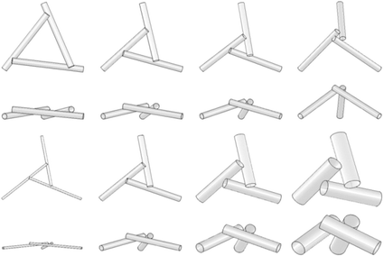
Engagement length variations for simple fans
-
(3)
the length of each element;
-
(4)
the style/orientation of the fan, which is called ‘right’ when it creates a clockwise moment, whereas it is identified as ‘left’ for an anticlockwise moment (Fig. 3);
Fig. 3 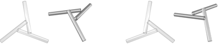
Style and fan orientation
-
(5)
the end disposition, which considers whether an element of a reciprocal configuration is placed above or below its support. In the first case, it is positive, while in the second it is negative;
-
(6)
the topology of the chosen grid.


With these parameters, it is possible to describe and automatically generate any basic configuration, as well as more complex ones, by conjoining individual fans.
Assembly and Growth
The assemblies of simple fans, which compose more articulated reciprocal systems, can be classified in several ways. From the architectural point of view, systems that generate flat and curved configurations are worth to be distinguished. For instance, superimposition of straight bars always results in a curved spatial structure, such as in the installation “Decay of a dome”, prepared by Amateur Architecture Studio and Vito Bertin for the Venice Biennale 2010. On the contrary, Serlio-like structures with notched beams are thought to realize flat slabs. The ceiling of the Music Room in Palazzo Piccolomini is a well-known example of this type (see Pugnale and Sassone 2014).
Another distinction can be made focusing on reciprocal systems growth. Leonardo’s bridge is a structure with linear extension, which we could call one-dimensional, or 1D. Domes are indeed surface-like structure and their development follows, conceptually speaking, two different directions. In a few cases, reciprocal systems grow in space without belonging to the previous categories; these can be considered as full 3D spatial structures. A design workshop on this topic was organized at Aalborg University in 2011, and the results are described in (Parigi and Pugnale 2014). It should be underlined that assemblies of reciprocal fans can be obtained from regular polyhedra too. In this family, tetrahedric, cubic and dodecahedric reciprocal configurations can be built with an identical fans aspect ratio (Baverel and Nooshin 2007).
Reciprocal Systems Based on Planar Elements: A Classification Attempt
When reciprocal systems are designed with elongated elements, design efforts are mainly focused on three aspects: (1) the definition of the fans to be assembled, (2) the study of their composition possibilities and (3) the selection of the jointing system(s). However, as suggested by the rare natural example of the cocolith, planar panels of different shapes can also be used to transfer forces in a reciprocal way. This inspires a new research direction. Reciprocal systems based on planar elements need a further effort for the design of composing elements themselves. The cocolith uses circular tiles, but also squares, triangles and more articulated or irregular geometrical shapes can be considered.
Materiality and jointing system are also enhanced in comparison to structures realized with elongated members. This is clearly visible in some of the furniture designed by Blaser (1992). Width and thickness of elements provide new design possibilities and also allow the designer to take advantage of surfaces instead of bars. With the use of planar elements, even a simple joint obtained through the superimposition of panels can offer several design possibilities, which need further investigation.
In order to guide future morphological studies, five categories of reciprocal configurations based on planar elements are proposed below.
Planar Elements Used as ‘Thick’ Linear Elements
This category includes all those reciprocal structures in which the composing planar elements are approached and used in the same way as elongated ones. Figure 4a shows a geodesic dome made of planar element with notches; Fig. 4b gives a more detailed view.

a Left a geodesic dome made of planar element with notches, b right detailed view
Only a few examples have been designed and built using thick linear elements, of which the Serpentine Gallery 2005, by Álvaro Siza and Cecil Balmond, is probably the most relevant. Here timber components were used as beams and their thickness allowed interesting interlocked joints to be realized. Another gridshell was designed by the students at the University of Melbourne, under the guidance of Eugene Cheah in 2012 (Fig. 5). Here, thickness variations of the rectangular sections also allowed the students to introduce integrated cladding elements.

Two views of the reciprocal structure realized by the students at the University of Melbourne in 2012. The nodes and construction have adopted the same principles used for the Serpentine Gallery 2005
In this category, the characteristic of a fan described in “Reciprocal Systems Based on Elongated Elements” are kept and each structure can be described according to their fan and the way they are arranged with respect to one another.
Planar Elements Used as ‘Groups’ of Linear Elements
This second category includes all those reciprocal structures in which the composing planar elements can be substituted by a fan of linear elements, i.e., the planar element conceptually groups linear ones to form reciprocal fans. In this case, focus is on the design of the composing element. Figure 6a shows the simplest example of a reciprocal structure belonging to this category, which is made of triangles that hypothetically replace fans of three linear elements each. Tiles can have three different engagement lengths, while only two are possible for elongated elements. These tiles can be transformed into a configuration with three linear elements that represent the edges of a triangle. The arrangement shown in Fig. 6c, on the right, is a six-vertice star element. The star shape is the only solution that can allow the elements to be placed one on top of another, as the tiles would otherwise overlap one another. This type of tile could have six different engagement lengths. Figure 6b shows a configuration made of crosses that replace fans with 4 linear elements.

Reciprocal configurations made with planar elements. a Left triangles, b centre crosses, c right star-shaped elements
Figure 7 shows a reinterpretation by Logan of Leonardo’s bridge, developed with planar elements (Logan 2008). Here, the tiles are connected by a slot that can be quite simple (Fig. 7a). However, by working on the shape of the composing element, more complex configurations could be obtained (Fig. 7b). This configuration connects several tiles together and, as shown in the elevation, a truss effect is created. The stiffness of the structure does not therefore depend only on the stiffness of a tile, but also on the equivalent truss.

A complex tile with slots and a possible resulting shape
Figures 8 and 9 show a system with triangular planar elements. One uses a flower-shaped element, the other uses a cut triangular element.

a Left example of a ‘flower shape’ planar element, b right a detailed view

a Left example of a ‘cut triangle’ planar element, b right highlight of the composing element
In this category, the notion of fan is kept but the elements are more complex. For instance in the configuration with triangular elements, the triangle have six engagement lengths.
Planar Elements that Transmit Bending Moment via the Notches
In this category, the notch between the tiles transmits a bending moment as shown in Fig. 10a. The assembly permits the bending moment to be transferred and gives structural stability to the configuration (Fig. 10b).

a Left a tile element, b right the resulting shape
In this category the notion of fan does not really exist, since elements are not lying on the top of one another. Since notches permit the transfer of bending moment, two elements can be connected with each other, omitting the notion of fan.
Planar Elements as Part of a Truss
In this category, notches allow the element to transmit tension or compression forces as shown Fig. 11, where a truss-like structure is generated.

Configuration where planar elements are parts of a truss
In this category, the notion of fan does not exist either. Notches are used to transmit tension or compression in the element, and are just a specific assembly for a truss.
Planar Elements Used as in Combination of Several of the Previous Four Categories
A configuration belonging to this category is shown in Fig. 12 (the entire sequence). A basic fan is obtained as a reciprocal structure of the first category with a small engagement length. By means of interlocking and superimposition, it can be extended in a surface-like way (Fig. 12b) or as a fully 3D structure (Fig. 12c). Figure 13 shows the built structure. This configuration is a mix of the first and the third category.

Reciprocal structure based on planar elements developed with the students of the École des Ponts in Paris. a Top realization of the basic fan, b centre growth as a surface-like structure, c bottom growth as a spatial structure

Two views of the prototype in full scale of the reciprocal structure drawn in Fig. 12b
Conclusions
The paper has presented a first exploration of reciprocal systems based on planar elements.
First, the parameters that define a reciprocal system with elongated elements have been mentioned. Then, configurations based on planar elements have tentatively been classified into five categories in which the composing panels can be seen as: (1) ‘thick’ elongated elements; (2) ‘groups’ of elongated elements; (3) notches that can transmit bending moment; (4) notches that can transmit compression and traction forces; (5) combination of some of the previous categories.
It should be underlined that the two first categories stand by friction-only. Several examples have been given for each category and a wide range of resulting geometries has been found.
This investigation and classification attempt had the aim of showing the morphological potential of reciprocal structures based on planar elements. It has also demonstrated the need for further geometrical, structural and construction explorations.
References
Baverel, Olivier, and Hoshyar Nooshin. 2007. Nexorades based on regular polyhedra. Nexus Network Journal 9(2): 281–297.
Baverel, O., H. Nooshin, G. Parke, and Y. Kuroiwa. 2000. Nexorades. International Journal of Space Structures 15(2): 155–159.
Baverel, Olivier, and Olga Popovic Larsen. 2011. A review of woven structures with focus on reciprocal systems—nexorades. International Journal of Space Structures 26(4): 281–288.
Blaser, Werner. 1992. joint and connection: trends in furniture and their background. Basel: Birkhäuser.
Douthe, Cyril, and Olivier Baverel. 2009. Design of nexorades or reciprocal frame systems with the dynamic relaxation method. Computers and Structures 87(21–22): 1296–1307.
Logan, H. 2008. Recherche de solutions structurelles de nexorades en plaques et ses applications en architecture. Master’s thesis, ENS Architecture de Versailles.
Parigi, Dario, and Pugnale Alberto. 2014. Three-dimensionality in reciprocal structures: concepts and generative rules. Nexus Network Journal 16(1). doi:10.1007/s00004-014-0183-y.
Pugnale, Alberto, and Sassone, Mario. 2014. Structural reciprocity: critical overview and promising research/design issues. Nexus Network Journal 16(1). doi:10.1007/s00004-014-0174-z.
Sénéchal, B., Cyril Douthe, and Olivier Baverel. 2011. Analytical investigations on elementary nexorades. International Journal of Space Structures 26(4): 313–320.
Author information
Authors and Affiliations
Corresponding author
About this article
Cite this article
Baverel, O., Pugnale, A. Reciprocal Systems Based on Planar Elements: Morphology and Design Explorations. Nexus Netw J 16, 179–189 (2014). https://doi.org/10.1007/s00004-014-0184-x
Published:
Issue Date:
DOI: https://doi.org/10.1007/s00004-014-0184-x