Abstract
Reciprocal systems based on superimposition joints, i.e. where un-notched bars sits on the top or in the bottom of each other, could be regarded as being intrinsically three-dimensional because of their natural out-of plane development. This paper presents seven of these three-dimensional configurations, conceived and built by the students of the Master of Science in “Architectural Design” at Aalborg University. They have been developed as an integral part of a 2-week workshop, organized and run by the authors during the fall semester 2011. Since physical models are instruments that trigger the exploration of new typologies because of the direct interaction they provide with the designer the students were called to deal with the issue of three-dimensionality in reciprocal systems through scale models and actual scale prototypes.
Three-Dimensionality as a Design Opportunity
This paper deals with a morphological aspect of reciprocal structures based on superimposition joints, that is, their natural out-of-plane development due to un-notched bars sitting on the top or on the bottom of each other. Such configurations present elements with unaligned axes, and can be regarded as intrinsically three-dimensional.
A famous example can be found in the Leonardo’s reciprocal arrangement (Fig. 1). Despite not being evident from the original plan representation on fol. 898 of the Codex Atlanticus, the configuration develops out-of-plane as a dome-like structure once elements are placed one on the top of the other (Fig. 2).

Sketch in plan of Leonardo’s reciprocal structure made of un-notched bars. Detail of fol. 898 from Leonardo’s Codex Atlanticus

The resulting geometry is not straightforward to predict and control. This is a consequence of the non-hierarchical nature of reciprocal assemblies: the position of each and every element determines, and is at the same time determined not only by the position of the elements immediately adjacent, but also by the position of all the entire set of elements in the assembly. The geometry of a network of reciprocally-connected elements can therefore be understood as a characteristic that emerges from the complex interaction between the elements’ shape, topology and position (Parigi and Kirkegaard 2014b).
In some cases, three-dimensionality in reciprocal systems has been explicitly avoided with the use of notched elements; notches of adequate depth have been used to realign the elements axes, defining a completely planar arrangement of beams. For instance, this strategy was adopted by Sebastiano Serlio for his proposal of a slab composed of elements shorter than the total span. The solution consisted in a planar reciprocal arrangement of short beams––although not detailed, his only drawing suggests the use of notches to interlock elements with their axes aligned (Fig. 3). Even a specific shape of the composing elements can result in a final planar configuration, such as in a prototype developed by Pizzigoni (2009) with concrete beams.

Serlio’s notched elements with aligned axis
On the other hand, the intrinsic three-dimensionality of reciprocal structures can be considered as a design opportunity, and can be approached by using both numerical tools and physical models.
The use of different numerical tools for the form-finding of reciprocal structures has been proposed in (Baverel et al. 2004) and (Douthe and Baverel 2009). A recent computational tool developed by Dario Parigi (Parigi and Kirkegaard 2013, 2014a) and called ‘Reciprocalizer’ is used to generate both regular configurations such as Leonardo’s structure shown in Fig. 2, as well as reciprocal configurations that adapt to virtually any possible free-form geometry (Parigi and Kirkegaard 2014b) by controlling and adjusting the following three parameters at each joint between two elements b i and b j :
-
the eccentricity e ij , which measures the distance between elements axes, directly dependent on the elements thickness and shape (Fig. 4);
Fig. 4 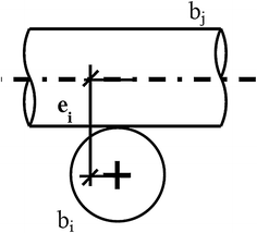
Eccentricity e ij
-
the engagement length l ij , that measure the position where each element is supported along the supporting element (Fig. 5);
Fig. 5 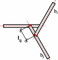
Engagement length l ij
-
the specification of whether element b i sits on the top or in the bottom of element b j with respect to a reference vector r j whose tip indicates the top position (Fig. 6):
Fig. 6 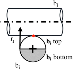
Top/bottom position


The use of such a tool significantly expands the design capacities of reciprocal structures for:
-
the possibility to solve and therefore predict the geometry of non-planar reciprocal configurations;
-
the possibility to explore the immense morphological richness of reciprocal structures, by generating multiple configurations in a short time, and their variations based on the changes in the values of geometric parameters.
A different and complementary approach comes from the use of physical models. Physical models are instruments that trigger the exploration of new typologies because of the direct interaction they provide with the designer: complex geometry can be easily conceived and built. One characteristic of the use of physical model is the freedom of the designer with respect to the topology of the configuration; another is the detachment from any codified, structured framework. For this reason, physical models can be regarded as the preferred tool during conceptual design.
In this paper we highlight the potential in the use of physical models by presenting seven configurations conceived and built by the students of the Master of Science program in ‘Architectural Design’ at Aalborg University.
A Framework for a University Design Workshop
A 2-week workshop was organized by the authors at Aalborg University during the fall semester 2011. It was conceived as an integral part of a Master’s course entitled ‘Engineering Architecture’, as a research-based activity in which the students were guided in:
-
identifying a research and design topic (in this case, structural reciprocity);
-
studying its background, relevance and current development in structural and architectural design (state-of-the-art in relation to basic reciprocal configurations, built projects, design tools and strategies using physical models and numerical tools);
-
highlighting a current design issue, in order to define potential developments for the generation of innovative concepts of structures and prototypes (Pugnale and Parigi 2012).
The workshop activity began with a 1-day lecture divided into four modules of 2 h each, alternating two modules of frontal lecturing with two hands-on modules dedicated to individual tasks. In the morning session, structural reciprocity was introduced with a set of images of different spatial configurations. Basic rules on how to construct reciprocal systems through physical models were also discussed. In the afternoon session, problems of representation as well as design tools of form-finding were presented and a first design task was assigned: the students had to define a set of two-dimensional patterns and then ‘break’ them to get three-dimensional configurations. This exercise was explicitly inspired by the artistic experiments by Rinus Roelofs, as shown in Fig. 7 (Roelofs 2008). Starting from that, during the 2-h exercise the students also developed other 3D configurations, reported in Fig. 8.

2D patterns and their respective 3D configurations by Roelofs (2008)

3D configurations by the students of Aalborg University
Development of 3D Reciprocal Systems: Workshop Rules
The research/design phase started during the second day of the workshop. In order to trigger the exploration of novel 3D configurations, the following rules were defined:
-
the structures must be extendable in more than one direction according to the Cartesian coordinate system;
-
the assemblies must not present any direct reference to surfaces;
-
the joints must be created through superimposition and un-notched bars.
Such limitations were aimed at concentrating the design efforts towards those spatial configurations which show the intrinsic three-dimensionality of reciprocal systems.
The first rule excluded structures that can expand in only one Cartesian direction. An example is provided by the Leonardo’s bridge represented in Fig. 9.

Leonardo’s bridge
Such a system is extendable in one direction by repeating the base fan. Even when we place two or more bridges side by side, in order to cover a larger span in the transversal direction, the system presents a unique longitudinal direction of expandability.
Structures that can be extended in two directions, and that therefore have a direct reference to surfaces, were excluded by the second rule. Figure 10 shows that these surface-like configurations can be easily obtained by repeating regular or non-regular patterns.

A reciprocal surface-like structure
They were excluded from the workshop as the results are often quite predictable, and because they have already been explored by several designers and researchers.
Structures that can expand in three Cartesian dimensions were the only ones accepted. However, special emphasis was placed on the third rule in order to exclude assemblies made of superimposition of different fans––in those cases, the joint between two different fans would not have been reciprocal, but simply constituted of two non-interlocked bars that would have required fixing with other connecting methods (Fig. 11).

Superimposition of different fans
The three rules refer implicitly to reciprocal systems based on the use of elongated/linear elements. The students were provided with timber sticks with a square cross section of 50 mm, the only material allowed for the realization of the prototypes. The maximum length of the elements was fixed at 3 m for reasons of transporting them. However, the construction of longer beams by means of conjoined elements was permitted.
All the structures were first developed through physical scale models, and then converted to actual scale prototypes.
Convergence to Seven Concepts of 3D Reciprocal Structures
Different strategies to generate three-dimensional structures were proposed. In the following sections, they are analysed according to the following aspects:
-
the generative rules;
-
the three-dimensionality and the potential for spatial growth;
-
the relation between structure and sequence of created spaces;
-
other considerations.
The identification of these features allowed a systematic generalization of the results. It can be helpful where the application and extension of these concepts is desired: an infinite number of variations and re-combinations is theoretically possible.
Structure 1: ‘The Bug’
Generative Rules
The structure we nicknamed ‘Bug’ can be interpreted as a modification of the bridge proposed by Leonardo. It originally consists of a linear array of base units made of six longitudinal and four transversal interlocked bars (Fig. 12), which determines a clear, single directionality in terms of expandability in space (as mentioned earlier, such a structure would be called ‘one-dimensional’).

Leonardo’s bridge units
In order to be modified into a system which develops in three directions, first the two central transversal bars, each one supporting the end of two longitudinal bars, are removed. The four longitudinal bars, now lacking support at one end, are then supported by the other two longitudinal bars. This requires a rotation around the interlocking point as shown in Fig. 13.

The generative rule
The new base unit is obtained and consists of two longitudinal, two transversal and four diagonal bars.
The generative rule consists in the composition of this modified base unit, following the same logic as Leonardo’s original pattern (Figs. 14, 15, 16, 17, 18).

The elemental fan (the ‘bug’)

Three-dimensionality

Two-dimensional array, plan (top) and elevation

A three dimensional array, plan (top) and elevation

The built prototype
Three-Dimensionality and Spatial Growth Potential
Thanks to the four diagonal bars, the base unit can expand in four different directions, and therefore they can be combined into two-dimensional arrays. Furthermore, each diagonal bar can be extended both upward and downward, enabling the possibility to create three-dimensional patterns of elements that develop in three dimensions at different heights.
Relation Between Structure and Sequence of Created Spaces
The space created by this system can be easily adapted to an architectural context. It can generate different levels, which are connected by sloping paths or ramps, and it can therefore be arranged to fit both related and independent spaces.
Other Considerations
Even though this concept has a great potential for infinite expansion in three spatial directions, the built model also highlighted some difficulties in the assembly: when a bar is placed at the wrong distance or angle with regard to the adjacent bars, any error in its placement not only affects the position of the bar itself, but also the overall geometry of the assembly. The prototype has therefore proved that a high level of construction precision is required.
Structure 2: ‘Matrix’
Generative Rules
The structure is based on the repetition of a reciprocal pattern (Fig. 19) in two orthogonal directions at each node intersection.

a, b The generative rule through the repetition of the Leonardo’s pattern
The original pattern (Fig. 20) was discovered by Leonardo, and it can be found on fol. 899v of the Codex Atlanticus.

Plan view of the pattern of elements
The originality of the generative rule lies in the fact of transforming the well-known two-dimensional pattern into its corresponding three-dimensional structure. In keeping with this rule, there are no continuous bars that span the entire structure in all three directions, and the three-dimensional configuration extends according to the generative rule of the two-dimensional pattern.
The structure is based on the node of Fig. 21, which makes it possible to deal with three bars coming from three different orthogonal directions.

The joint with engagement length equal to zero
Three-Dimensionality and Spatial Growth Potential
The structure can be expanded indefinitely in space in every direction.
Relation Between Structure and the Sequence of Created Spaces
The prototype is a cube with extending legs elements that suggest the indefinite expandability of such configuration in three directions (Fig. 22).

The built prototype
The final model appears as an orthogonal ‘architectural frame’ (Fig. 23). It also suggests the possibility to generate different space frames with different starting two dimensional patterns.

Detail of the built prototype
Other Considerations
The configuration is characterized by a joint type (Fig. 21) for which the transfer of forces in a reciprocal way can be considered as at the limits of the structural principle.
In fact, the engagement length, which is characteristic of reciprocal configurations, is equal to zero. However, the joint maintains the typical interlocking of reciprocal joints.
Structure 3: ‘Neural Network’
Generative Rules
The basic unit of the ‘neural network’ rule can be created by interlocking a positive reciprocal fan (Fig. 24) into a negative one (Fig. 25).

Positive fan

Negative fan
The assembly requires the presence of two different engagement lengths for the two fans, in order to insert the smaller into the engagement window of the other (Fig. 26).

Combined positive and negative fan
Three-Dimensionality and Spatial Growth Potential
The potential of such a generative rule lies in the three-dimensional node it creates, which can expand in six different directions: three towards the bottom (correspondent to the three bars of the positive fan), and three towards the top (corresponding to the three bars of the negative fan). The two interlocked fans can also rotate relatively to each other, and the six directions in which they are pointing are therefore variable (Figs. 27, 28).

Relative rotation of the two interlocked fans

The base joint built by the students
Relation Between Structure and the Sequence of Created Spaces
The built structure (Fig. 29) demonstrates that the node enables the possibility to freely design spatial structures by combining the nodes at different heights and positions, with almost unlimited extension possibilities. Architecturally, this concept can be seen as an open-ended system in which the issue is related to the design of its ending points (Fig. 29).

The built prototype of the ‘neural network’
Other Considerations
The joint is extremely flexible and functional. However, in order to be rigid, all six composing elements must be present. This forces the use of unnecessary elements when less than six elements converge in the node, and might constitute an overall drawback or limit of the concept. In the built prototype, the problem was solved using very short elements to complete the joints, when less than six bars were converging.
Structure 4: ‘Monkey saddle’
Generative Rules
This structure is built iteratively by adding outer layers of reciprocal fans to a starting basic configuration made of three elements. The new bars have to be added one by one, as shown in the sequence of Fig. 30, until a desired shape, or a physical limitation, is reached.

Generative sequence: outer layers of reciprocal fans are added to the base unit
The bar length always needs to extend sufficiently over the meeting points to accommodate and support further additions.
Three-Dimensionality and Spatial Growth Potential
The growth possibilities of this concept are strictly related to the number of elements of the starting fan. For instance, when it is made of three elements, the system develops in space in six directions: three towards the ground and other three looking at the sky (Fig. 31).

1:10 scale model
With a fan of four elements, the system already develops in eight directions. Starting fans made of five and more elements develop in ten or more directions according to the same logic.
The regularity of the final geometry is related to the dimensions of the starting fan––identical elements with equal engagement lengths and eccentricities grow maintaining the same proportions in every direction, while differences in these parameters result in non-regular or deformed structures.
Relation Between Structure and the Sequence of Created Spaces
According to the construction scale, this concept could be applied in several contexts and situations. At a larger scale, it can work as a singular sculptural object in open space, integrating for instance specific functions such as lighting and protection, but also as a column-like structural element, supporting a roof like in the case of the ‘Palazzo del Lavoro’ by Nervi. At a smaller scale, it can be designed as a piece of furniture, such as a chair or a table (Figs. 32, 33).

View of the engagement window. The reciprocal fans only touch towards the extremities

The built prototype of the ‘monkey saddle’
Other Considerations
The application of this concept seems to be more appealing when geometrical regularity is maintained. In this way, the simplicity of the generative rules is highlighted, resulting in a sculptural structure. However, the control of precision throughout the construction is very difficult in practice because of the interdependence of the elements.
Structure 5: ‘Star Frame’
Generative Rules
Starting from a six-bar fan, where bars extend in both directions before and after the contact point (Fig. 34a–c), an outer array of bars is added (Fig. 34e)––each and every new element is supported by two bars facing opposite of the first fan (Fig. 34d). A final array of six bars is then added (Fig. 34g), finding supports on one bar belonging to the first fan and another one on the second array (Fig. 34f).

The generative sequence of the ‘star frame’
Three-Dimensionality and Spatial Growth Potential
The configuration creates a seemingly random ‘cloud’ of bars (Fig. 35), in which each bar points towards a different direction and there is no reference to any surface. The system seems to work as a closed configuration, as it does not allow for further expandability.

The final scale model
Relation Between Structure and the Sequence of Created Spaces
The integrity of the space it creates is a product of the fact that the top elements are interlocked and constitute a whole with the elements that go to the ground.
Other Considerations
Although the structure could grow potentially indefinitely around its centre, the spatiality of the generative rule, and the complexity of the resulting geometry, render extremely hard to continue the growth after the third array of elements is added. However, the realization of the first three set of bars was the easiest among the seven prototypes built (Figs. 36, 37).

View of the engagement window of the built prototype

The built prototype of the ‘star frame’
Structure 6: ‘Flame’
Generative Rules
Starting from a fan made of three bars, a first array of three new elements is added (Fig. 38a, b): for each new bar, one of the two extremities touches the ground and the three together become the only supports of the structure. As shown in Fig. 38c, a second array of three elements is then added between the bars of the starting fan and the new ones of the first array. Following the same logic, a third set of three bars is finally added between elements of the first and second arrays. Such a generative rule suggests that the operations mentioned above could theoretically be repeated again, for several other now starting from the third array, a three-bar fan similar to the initial one (Fig. 39).

Generative sequence of the ‘flame’ concept, in its indefinitely expandable version

Generative sequence of the built converging ‘flame’ structure
Three-Dimensionality and Spatial Growth Potential
The repetition of the generative rules for several iterations can lead to two opposite results: depending on the angles created between bars, the model can create either a reciprocal tower, which would be indefinitely expandable, or a closed up sculptural flame, such as in the case of the built prototype (Figs. 40, 41).

Several scale models were built in order to understand the growth possibility of the ‘flame’ concept

The built prototype of the ‘flame’
Relation Between Structure and the Sequence of Created Spaces
The ‘flame’ configuration creates a conical or cylindrical internal space, simply by taking advantage of the reciprocal superimposition joint and variations in the connection angles.
In the built prototype, the tower converges in a single node after four iterations of bar additions; it does not offer the possibility to continue indefinitely, but further experimentations, together with more sophisticated construction techniques, could lead to the realization of a indefinitely expandable structure.
Other Considerations
The transformation of the scale models into a real prototype showed that the geometry is extremely difficult to control, because of the interdependence of the structural elements. Furthermore, the lower layers of bars are structurally more stressed than the higher ones. This can imply the use of elements with a variable cross section, adding a further degree of complexity to the development of this concept.
Structure 7: ‘Wave’
Generative Rules
The wave combines fans made of four bars with others made of three elements. First, a grid-shell made of four-element fans is defined. Two parallel and opposite elements for each fan are then extended in length. This allows the generation of several new fans made of three elements, all perpendicularly oriented with respect to the hypothetical surface that the grid-shell defines (Figs. 42, 43).

Scheme of the generative sequence. The elements are represented as an unfolded assembly of the final grid-shell structure

Scale model of the ‘wave’ concept
Three-Dimensionality and Spatial Growth Potential
Even though the ‘wave’ derives from a surface-like assembly, it can be considered as a 3D concept because quadrilateral and triangular fans develops, respectively on perpendicular planes.
The starting grid-shell, made of four-element fans, always guides the spatial growth of the ‘wave’. Theoretically, both long roofs, such as in the case of the new Milan Trade Fair by Studio Fuksa, and small pavilions can be developed by applying this concept.
Relation Between Structure and the Sequence of Created Spaces
The ‘wave’ encloses a space where the interaction between the two typologies of fans is responsible of the overall stability. The structure manifests itself in the different aesthetic qualities of the exterior and interior sides. The external skin expresses a ‘scale’ pattern, which could also be developed as an interesting and structural shading device (Fig. 44).

The built prototype of the ‘wave’
Other Considerations
During the workshop, the presence of four bar fans generated stability problems in the initial grid-shell structure. Even the addition of new three-bar fans was not enough to reach a stable configuration, and the structure needs further bracing systems to be practical.
Conclusions
In this paper, seven concepts of reciprocal structures built using un-notched standardized elements have been presented. The different design proposals have been conceived and developed during a construction workshop at Aalborg University, with the aim of exploring the intrinsic three-dimensionality given by the superimposition joint.
The generative rules of the built prototypes, as well as the spatial growth potential of the design concepts have been here described in order to provide a systematic overview of the workshop results.
The schemes proposed were developed in a research-based environment, and their scope is intended for use as the starting point for the development of further variations of the same concepts or some real application in an architectural context.
References
Baverel, Olivier, Hoshyar Nooshin, and Y. Kuroiwa. 2004. Configuration processing of nexorades using genetic algorithms. Journal of the International Association for Shell and Spatial Structures 45(2): 99–108.
Douthe, Cyril, and Olivier Baverel. 2009. Design of nexorades or reciprocal frame systems with the dynamic relaxation method. Computers and Structures 87(21–22): 1296–1307.
Parigi, Dario, and Kirkegaard Poul H. 2013. The reciprocalizer: a design tool for reciprocal structures. In Proceedings of Civil Comp Press, Cagliari, Italy, 3–6 September 2013.
Parigi, Dario, and Kirkegaard Poul H. 2014a. The reciprocalizer: an agile design took for reciprocal structures. Nexus Network Journal 16, 1 in this same issue.
Parigi, Dario, and Kirkegaard Poul H. 2014b. Design and fabrication of free-form reciprocal structures. Nexus Network Journal 16, 1 in this same issue.
Pizzigoni, Attilio. 2009. A high fiber reinforced concrete prototype for reciprocal structures of demountable building. In IASS Symposium 2009. Evolution and trends in design, analysis and construction of shell and spatial structures, eds. A. Domingo, and C. Lázaro C, 1895–1906. Valencia: Editorial de la UPV.
Pugnale, Alberto, and Parigi Dario. 2012. Approaching technical issues in architectural education. In Proceedings of the IASS-APCS 2012, Seoul, 21–24 May 2012.
Roelofs, Rinus. 2008. Two- and three-dimensional constructions based on Leonardo grids. Nexus Network Journal 10(1): 17–26.
Acknowledgments
The authors would like to thank the Department of Architecture, Design and Media Technology, Aalborg University for providing us working spaces and funds, the students of the 1st semester of the Master of Science in ‘Architectural Design’ at Aalborg University for their intense participation to the workshop, Prof. Poul Henning Kirkegaard for encouraging us in organizing this activity and Nathalie Balfroid and Marie Frier for their active collaboration during the whole process.
Author information
Authors and Affiliations
Corresponding author
About this article
Cite this article
Parigi, D., Pugnale, A. Three-Dimensionality in Reciprocal Structures: Concepts and Generative Rules. Nexus Netw J 16, 151–177 (2014). https://doi.org/10.1007/s00004-014-0183-y
Published:
Issue Date:
DOI: https://doi.org/10.1007/s00004-014-0183-y