
Abstract
Tou-Kung, which is pronounced in Chinese and known as Bracket Set (Liang & Fairbank, A pictorial history of Chinese architecture, 1984), is a vital support component in the Chinese traditional wooden tectonic systems. It is located between the column and the beam and connects the eave and pillar, making the heavy roof extend out of the eaves longer. The development of Tou-Kung is entirely a microcosm of the development of ancient Chinese architecture; the aesthetic structure and Asian artistic temperament behind Tou-Kung make it gradually become the cultural and spiritual symbol of traditional Chinese architecture. In the contemporary era, inheriting and developing Tou-Kung has become an essential issue. Several architects have attempted to employ new materials and techniques to integrate the traditional Tou-Kung into modern architectural systems, such as the China Pavilion at the 2010 World Expo and Yusuhara Wooden Bridge Museum. This paper introduces the topological optimisation method bi-directional evolutionary structural optimisation (BESO) for form-finding. BESO method is one of the most popular topology optimisation methods widely employed in civil engineering and architecture. Through analyzing the development trend of Tou-Kung and mechanical structure, the authors integrate 2D and 3D optimisation methods and apply the hybrid methods to form-finding. Meanwhile, mortise and tenon joint used to create stable connections with components of Tou-Kung are retained. This research aims to design a new Tou-Kung corresponding to “structural performance-based aesthetics”. The workflow proposed in this paper is valuable for Architrave and other traditional building components.
Find the latest articles, discoveries, and news in related topics.Avoid common mistakes on your manuscript.
1 Introduction
Chinese ancient architecture has a long history and a self-contained system. Regarding building materials, China’s vast territory, various timber, and large bases have led to the gradual formation of the tectonic system based on a wooden framework through the dynasties. The development of the timber frame has also become the central vein of China’s architectural development. Tou-Kung plays an essential role in the Chinese wood tectonic system. It is an indispensable supporting element in Chinese timber-frame buildings that supports the weight of the overhanging eaves. Meanwhile, it symbolises the feudal hierarchy and an indispensable cultural character in traditional Chinese architecture. It is a complex member located at the junction of the column and the beam, made up of arms (Kung) and blocks (Tou). At the base of Tou-Kung, it is a large block called Lu-Tou. Crossed arms spreading in four directions are set into Lu-Tou. These in turn bear smaller blocks (Shan-Tou) that carry longer arms. Hua-Kung extends outward, while the others parallel to the wall are called Transverse Kung as a group, including Ni-Tao-Kung, Man-Kung etc. Long cantilever arms called Ang extend out to support the outermost purlins (Fig. 1) (Liang & Fairbank, 1984). In an era where digital design is booming, the research present here tries to combine the conventional Tou-Kung with advanced structural form-finding methods to create a new derivative of Tou-Kung that incorporates ancient and modern elements. The inheritance and innovation of Tou-Kung have become a significant concern. This paper focuses on using the evolution of traditional building components to document the development of architectural techniques in a new era.

Principal parts of a Chinese timber-frame building
2 Translations and derivation practices of Tou-Kung
From a contemporary standpoint, several architects have attempted to translate the traditional Tou-Kung, employing new materials and techniques to integrate it into modern architectural systems. These can be broadly divided into three categories according to structural role, form, and cultural symbolism.
2.1 The dendritic column with structural bionics design
The application of dendritic columns in the spatial structure solves the problem that a single vertical column with an equal cross-section is challenging to set off the far-reaching eave, in accordance with the function of the tiered projections of Tou-Kung. The dendritic column is upright and looks like a tree trunk (Qian et al. 2020). It has various branches at the top of the column, geometrically dispersed to form multiple points of support and radiating away from the centre of the column (Fig. 2A). Although the dendritic column satisfies the integration of “force” and “form”, achieved straightforward transferred force and material efficiency, and it differs from Tou-Kung in appearance.

A Dendritic column: B Archaize Tou-Kung; C The cultural imagery of Tou-Kung
2.2 Archaise Tou-Kung using contemporary tectonic methods
Archaise Tou-Kung is constructed from high-strength materials such as cement and aluminum alloy, imitating or copying Tou-Kung from various historical periods (Fig. 2B). The same are the beams, columns, Tou-Kung and pillars in archaise buildings. Still, they are not optimised for the mechanical properties of the individual materials. As a result, the overall stiffness and the structural frequency of archaize buildings are excessive (Wang, 2011), leading to enormous material waste and the loss of characteristics of the traditional Tou-Kung as simple, efficient, and exquisite.
2.3 Cultural symbols of Tou-Kung
This type of building has a superficial structure that exhibits layer-by-layer stacking, achieving a cultural homage to Tou-Kung (Fig. 2C). In the case of the China Pavilion at the 2010 World Expo, the traditional Tou-Kung is simplified through dislocation, orthogonality, and classification in three-dimensional construction. While the mechanical characteristics of force transferred from one layer to another are retained (Xu & Liu, 2018). However, this type of abstract translation detracts from the essential structural role of Tou-Kung and the corresponding scale of its components. It serves only as an abstract derivative and a metaphor for Tou-Kung culture.
3 Introduction and analysis of Tou-Kung
3.1 The evolution of Tou-Kung
The evolution of Tou-Kung is a nearly comprehensive presentation of the development of architectural skills and the aesthetic trends of building components in each period of Chinese history. Tou-Kung is not only a single structural component, but also has multiple-layered significance in cultural inheritance, decoration and beautification, class identity, measurement, etc. The variations of Tou-Kung have also provided important evidence for identifying the age of ancient architecture and observing the style of different times.
The development of Tou-Kung can be briefly divided into five stages. Firstly, from the Western Chou Dynasty to the Han Dynasty, the image of Tou-Kung was depicted in various historical relics (Fig. 3A). After the Han Dynasty, it appeared between the columns. Secondly, in the period of Wei, Jin, Southern and Northern Dynasties, the form of Tou-Kung gradually became standardised, and the classic forms of inverted-V brackets appeared (Fig. 3B). Thirdly, from the Sui and Tang Dynasties to the Five Dynasties, Tou-Kung was vigorously gorgeous and magnificent, characterised by the huge body (Fig. 3C). Seen from the elevation, the height of Tou-Kung can reach the half-height of the column. Transverse Kung and column-top joists overlap to form a lattice-shaped framework. As a strengthened node, Tou-Kung also becomes an indispensable part of the structure. Fourthly, during Song and Yuan Dynasties, the image of Tou-Kung became tenderly beautiful. Since Song Dynasty, the number of Tou-Kung has increased, and the volume has decreased. A certain decorative effect was introduced. The size of components started to be unified, and the modular system appeared (Fig. 3D). The last was the Ming and Qing Dynasties. By the Qing Dynasty, Tou-Kung adopted the modular of the mortise of Lu-Tou, which was used to standardise the dimensions of each component of it (Fig. 3E). Decorative and coloured paintings appeared on the surface of Tou-Kung, which further strengthened the decoration and weakened the structure roles. At this stage, Tou-Kung ceased playing the role of keeping the overall framework stable.

The evolution of Tou-Kung
Throughout its history, Tou-Kung has evolved from large to small, from simple to complex, with its structural role diminishing and its decorative role strengthening. As technology and materials developed, Tou-Kung has switched its role from load-bearing to decorative and from function to form in the process of meeting the demands of the times. The ideal state of the development and derivation of the contemporary Tou-Kung is to reflect the technological development of the new era while preserving the historical heritage. The focus of this paper is not to simply restore Tou-Kung of a certain period or use modern materials to make a traditional form of Tou-Kung, but to combine new technology and new materials with traditional architectural techniques, exploring the profound traditional architectural spirit with a high degree of unity of structure and form (Yuan et al., 2017), and seeking resemblance rather than mimesis.
3.2 The structural function and mechanical prototype of Tou-Kung
Tou-Kung, placed between beams and columns, plays the key role of a connecting link. And the load of the roof and the upper structure is transmitted to the spreading layer of Tou-Kung, and then to the column and foundation. As a structural “transit hub”, Kung is paved up layer by layer, and the truss and purlin on the outermost layer are propped further for a longer distance, which supports the far-reaching eaves of the structure and makes it more imposing and magnificent (Fig. 4A).

The structural function and mechanical prototype of the Tou-Kung
The mechanical prototype of Tou-Kung is essentially a short cantilever beam (Fig. 4B), whose main structural function is to support the load of eaves (Yu et al., 2006). For the cantilever beam, the increased height of the beam from outside to inside can ensure overall strength and stability. So, Tou-Kung rises in tiers or “jumps” and extends outward in steps, and through the mortise-tenon joint, several beams become whole, which increases the bending and shearing resistance of Tou-Kung. As supporting the eaves, the beam sometimes appears extremely long, and the distance between the bearing beam end and the bearing support is excessively large, leaving a large force arm and a weak beam bearing capacity, which makes the beam easy to break. Therefore, from the end to the starting point of the overhanging part, Tou-Kung adopts the way of layer-by-layer superposition and layered force transmission to ensure overall stability.
Tou-Kung is a combined structural member, which needs to be disassembled into several components when studying its force transmission characteristics to present its layer-by-layer force transmission properties clearly (Fig. 5). The key mechanical components of Tou-Kung can be dissembled into Tou (blocks), Kung (arms) and Ang (long cantilever arms) (Liang & Fairbank, 1984). Specifically, Tou is a square wooden block used to support Kung and Ang. The Tou mainly works as cushions to transfer the pressure from the upper structure, transporting the small buckets from top to bottom to the Kung connected below (Wei, 2007). Among these Kung, the Lu-Tou at the bottom of Tou-Kung, which is called Lu-Tou, is the most important compression member of the Tou-Kung system. Kung is a bow-like part. Hua-Kung is vertical to the building facade, responsible for overhanging, while Transverse Kung is parallel to the building facade, which plays a balancing role. Hua-Kung and Transverse Kung bear the bending moment and longitudinal load, respectively. The pressure from the upper structure is concentrated at the middle and the two ends of Hua-Kung, resulting in a large bending and shear stress at the head of Hua-Kung (Lv, 2010). However, the use of Transverse Kung can support the upper structure outside the Hua-Kung plane, strengthening the connection between Tou-Kung and the upper structure, improving the overall bending and torsional strength of Tou-Kung, and making Tou-Kung stable spatial support in all directions. Ang is the longest member in Tou-Kung, which sags diagonally and is structured as a cantilever beam in the oblique direction. Ang is a compression member due to its large cross-section area, which can bear the lifting load of the eaves and transmit the pressure from the upper parts. In addition to compression, Ang also carries a certain level of bending moment. The components of Tou-Kung are interlaced and stacked, full of rhythm changes.

Layer-by-layer force transmission system of Tou-Kung
4 Topology optimisation of Tou-Kung
In this experiment, the bi-directional evolutionary structural optimisation (BESO) method has been applied to the design. The concept of BESO is to find a preliminary structural configuration which meets a predefined criterion based on finite element analysis. As an advanced form-finding method in digital design (Lin, 2020; Zhao and Chen, 2016), topology optimisation can optimise the layout of materials and explore new forms of a contemporary bucket set on the premise of a reasonable structure (Xie et al., 2014). BESO method has been implemented into architectural design in many pieces of research due to its capacity to generate diverse organic forms with high structural performance (Bao et al., 2022; Yan et al., 2022). During the design process, the scale and position of the traditional Tou-Kung are inherited. Also, the hybrid method for optimization is introduced. Tou-Kung is divided into several components according to the force characteristics of the individual elements. Therefore, the structural prototype of layer-by-layer force transmission is reserved. Through the digital form-finding and finite element analysis, a new Tou-Kung is designed on the premise of material efficiency and ensuring definite force transmission routes and a reasonable structure (Fig. 6).

Topologically optimised Tou-Kung
4.1 Design methodology
The Ameba plug-in is implemented to carry out topology optimisation and BESO algorithm based on the Rhino and Grasshopper platforms (Zhou et al., 2018; Zhou, 2021). In the application of topology optimisation, the rational distribution of Tou-Kung materials is realised by deciding the removal, reservation, or supplement of materials through finite element analysis (Fig. 7).

Workflow of Tou-Kung optimisation & exploded diagram of optimised Tou-Kung
The design transforms Tou-Kung in the Ming and Qing Dynasties. In that period, the Ang was fake, and didn’t have the structural character of lower Ang in the Song Dynasty. The force transmission of Tou-Kung in the Ming and Qing Dynasties is neater and better aligned with the property of layer-by-layer force transmission from top to bottom. In topology optimisation, it is also the most effective structural morphology to transmit the upper load with specific boundary support, material consumption, and material type. To keep to the layer-by-layer force bearing and transmission mode of each part of Tou-Kung, this study adopts the concept of “zoning optimisation” in the Multi-volume BESO method (Yan et al., 2022) as the core logic of Tou-Kung optimisation. Specifically, Tou-Kung is divided into Tou, Kung, Ang, and other parts, and then they are respectively optimised by BESO/Ameba; later, all optimised parts are reconstructed and assembled.
This calculation framework (Fig. 7) is derived from the optimization process of Tou-Kung and is based on the combination of the topology optimisation method and the zoning optimisation method. Zoning optimisation can be applied to the optimization of the different scales of components. More specifically, the components can be divided according to the number of storeys of the partitions, the volume of the partitions and the different positions of the partitions in the building, in order to satisfy the optimisation calculation of components in different scales. In the case of this chapter, the zoning optimisation of Tou-Kung, a small-scale, multistorey building element, will be calculated in Sections 4.2 and 4.3. Then the zoning of the architrave-column combination, a large-scale, low-storey building element, will be calculated in Section 4.4, which can further illustrate the compatibility and rationality of the framework for optimising building elements at different scales.
4.2 Topology optimisation form-finding of 2D Tou-Kung
The 2D topology optimisation and planar force analysis are conducive to the subsequent 3D structure form-finding of Tou-Kung. In addition, the 2D optimised results can be compared with the 3D optimised ones to decide the rationality of the results and provide a reference for adding supplements, resetting boundary conditions, and optimising parameters. In the zoning optimisation of 2D Tou-Kung, the primary parts, including Lu-Tou, Shan-Tou, Ni-Tao-Kung, Ling-Kung, Hua-Kung, and Kua-Tzu-Kung, are extracted. Kua-Tzu-Kung on the central axis of the column is selected as representative of component composition simulation analysis. Firstly, the planar angle of each component is selected, and the ratio scale of each element is determined according to the Tou-Kou module system in the Qing Dynasty. Taking “Tou-Kou” as the modulus unit, an accurate 2D model of each component is constructed. Then according to the descriptions of the force bearing of each part of the structure and the connection mode between Tou and Kung in Ying Zao Fa Shi (Li & Liang, 1983) and Engineering Practice Rules and Examples from Qing Dynasty (Liang, 2003), the force diagram of components is drawn for 2D force analysis. Secondly, the load and support are set as boundary conditions after generating the mesh element in Rhino/Ameba, and parameters for preprocessing are set to run the BESO algorithm for seeking optimal 2D topology structural forms (Fig. 8).

2D topological optimised components of Tou-Kung
The 2D topological optimized results and the force analysis shows a significant reduction in materials at both ends and wall of Tou-Kung. Ancient carpenters used the entasis method to make the ends of Tou-Kung into gentle curves or fold with a full and soft appearance. The material layout of Tou-Kung after topology optimisation is similar to the form of the traditional Tou-Kung after entasis treatment. From force analysis, the corner in the traditional Tou-Kung is a non-force bearing part or a part with less bearing load. Therefore, the entasis part’s material deletions outnumber that of other parts after topological optimisation. The ancients artificially omitted the corner material based on their construction experience, thereby developing the practice of entasis. This is an experimental result of artificially saving materials and efficiently expressing structural force transmission.
4.3 Topology optimisation form-finding of 3D Tou-Kung
After previous 2D component decomposition optimisation, we found three issues that should be considered in the 3D optimisation:
-
1.
Low strength of the wall of Tou-Kung
The wall of Tou-Kung is the smallest individual component, and it has a large volume difference compared to other components. Considering the different shapes and low strength of the wall of Tou-Kung after topology optimisation, Shan-Tou is combined with Kung in the 3D prototype, and a typical combination of Tou and Kung, which can be described as one block on the bottom, one arm in the middle and three small blocks on the top, is formed (Fig. 9).
Fig. 9 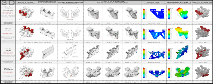
3D topological optimised components of Tou-Kung
-
2.
The dangerous critical cross-section
During the 2D optimisation, the rabbets of Lu-Tou, the first layer Kua-Tzu-Kung and the first layer Hua-Kung complement each other with overlapped dangerous sections with hidden safety hazards. Therefore, we combined the three components with the central part as the integrated component to supplement the strength of the critical section further.
-
3.
Recurrence of entasis
To further verify the significance of entasis in terms of rational force transfer and material saving, the geometric prototype of Tou-Kung is simplified during the 3D optimisation, and the entasis chamfer was cancelled to form a simplified, integrated cube. The purpose is to determine whether material deletion and chamfer would reappear at the original entasis position in the optimised structure. At last, four combinations were formed: one Tou with three Shan-Tou, three Tou with three Shan-Tou, the combination of the Ang and Hua-Kung, and the combination of Lu-Tou and Hua-Kung. Then 3D optimisation is performed and comparatively analysed with the 2D optimisation results. Parameters are adjusted to achieve the optimal solution for topological optimised Tou-Kung.

According to the results of the 3D optimisation, several combinations of Tou-Kung have presented structural shapes of oblique fractal bifurcation from the support to the load ends. This mechanical structure is similar to the structural prototype of the tree-like column and the fractal structure of tree branches in nature, proving the high correlation and similarity between Tou-Kung and tree branches in the mechanical prototype. The upper and lower surfaces have complete materials for the structure of Shan-Tou, while the middle part is a porous structure. Massive materials were cut for the original entasis position or even an “entasis style” was formed. The chamfering amplitude of these designs was more obvious than in traditional Tou-Kung (Fig. 10). The topology optimisation results also reflected the wisdom of ancient craftsmen and the excellent craftsmanship of Tou-Kung, which is absolutely an architectural gem that integrated form and force (Fig.11).

Topology optimisation results of the entasis part of Tou-Kung

3D topological optimised Tou-Kung models
4.4 A case study and topological optimisation experiment of the Hall of Prayer for Good Harvests
Architrave is also an important part of the Chinese timber frame. Usually, an architrave is installed on the top of a column to link Tou-Kung between columns with the load-bearing horizontal member. In some architectures, large and small architraves were stacked and juxtaposed with the middle connected by a clamp pad (Cao & Wang, 2010). These architraves were simplified as a complete geometric graph and were used as the optimised prototype together with the eave column. In the former research, in spite of the layer-by-layer force transmission and mortise-tenon joint of Tou-Kung, the zoning optimisation was applied to form-finding of topologically optimised Tou-Kung. This approach can be applied not only to the form-finding of the scale of Tou-Kung, but also to the scale of the building. In the following, we will verify the feasibility of our workflow through the optimisation of the architrave and column. During the architrave topology optimisation of the Hall of Prayer for Good Harvests, the combined member of a ring of architrave and eave column can be disassembled into six same units according to the symmetry. Then the 1/12 minimum optimisation unit can be obtained based on the symmetric properties of the units (Fig. 12).

3D topological optimised architrave-column combination
For the load arrangement, the downward uniform load can be set on the upper critical plane connecting Architrave and Tou-Kung, and a side thrust can be im- posed on the sparrow brace, which ensures that all the units are closely connected in the partition optimisation. The base was installed at the position of the symmetrically optimised vertical cross-section and column bottom. The overall effect after optimisation was shown in the image (Fig. 13).

3D topological optimised components in ancient buildings
After the optimization of Architrave, the results with the previous optimization results of Tou-Kung were combined. Then, the corresponding original structure of the Hall of Prayer for Good Harvests was replaced while retaining the traditional paintings, doors, windows, tiles and other decorative components. The overlap of new and old elements formed a stark contrast in appearance (Fig. 14) while maintaining the same mechanical essence. This kind of hidden link ensures a more rigorous connection between culture and structure based on the unity of aesthetic form and force in contemporary structure.

Topological optimised Hall of Prayer for Good Harvests
5 Structural optimisation strategy for the members of Tou-Kung based on the mortise-tenon joint
5.1 Overview and classification of the mortise-tenon joint in Tou-Kung
In the structure of the traditional Tou-Kung, multiple members stepped layer outwards layer by layer, forming a structural layer that transmits the layer-by-layer force between the roof and columns. As a structural connection method, the mortise-tenon joint connects individual members without using a single nail or bolt (Zhang, 2022), which only uses the geometric connection between the members with concave-convex compensation for the shape to achieve an efficient and secure connection (Wang, 2019). In the mortise-tenon joint, “tenon” is the convex part, and “mortise” is the concave part ([Liu and Song, 2019), with a variety of derived forms, which realise the horizontal and vertical connection between all the members of Tou-Kung (Fig. 15).

The use and classification of mortise-tenon joint in Tou-Kung
The use of the mortise-tenon technique in Tou-Kung can be summarized into two types: the mortise-tenon joint and the mortise-mortise joint. In the first type, the concave and convex parts interlock with each other and form a strong, stable and flexible framework (Fig. 15B). Mortise-tenon joint is commonly seen in the connection of the top of the column with the bottom of Lu-Tou, as well as Shan-Tou with cross mortise with their lower members. This type of mortise-tenon technique allows the connection structure to be hidden in the members’ own volume without protruding from the body block, thus preserving the integrity of the appearance of Tou-Kung. Meanwhile, the height of the two layers of members is also retained with this combination.
The second type is mortise-mortise joint (Fig. 15A). “Mortise” is the concave part. Two “concave” members are lapped in the mutual perpendicular direction in Tou-Kung between columns and are buckled in other angular directions in the corner Tou-Kung. This type of connection is widely used between Transverse Kung and Hua-Kung, or Transverse Kung and Ang. As two “concave” members are lapped together in a position that cuts 1/2 of the height of the single-layer member, the complementary joint becomes a finished type and still retains the height of the single-layer member.
In summary, the mortise-tenon joint is suitable for the connection between different layers of members, while the mortise-mortise joint is suitable for the connection of members at the same horizontal layer (Liang et al., 2021). The joint use of the two methods forms the basis for the layer-by-layer force transmission in Tou-Kung, which is also an indispensable technical path to achieve the façade modelling of “corbelling”.
5.2 Problems and solutions to the structural optimisation in mortise-tenon joint
Topology optimisation often presents structural retention of unit volume, and mortise-tenon joint usually raises a high-volume correspondence requirement to ensure sufficient interlocking between the concave and convex parts. Therefore, it became the focus of this study to make topology optimisation of the members in Tou-Kung to eliminate low-efficiency units to ensure the lightweight structure of Tou-Kung while retaining the unit at the mortise-tenon joint part and ensuring the complementary concave and convex volumes at the mortise-tenon joint with high accuracy. This issue can be further summarized as the “structural optimisation strategy for the members of Tou-Kung based on mortise-tenon joint constraints” (Fig. 16).

The process of optimising the mortise-tenon joint in Tou-Kung
In the selection of the original domain of Tou-Kung, we chose the representative Tou-Kung with two “Jumps” on the architrave between two columns and selected the five-member combination of “Lu-Tou - Kua-Tzu-Kung on the central axis of the column - Shan-Tou on the top of Kua-Tzu-Kung - Hua-Kung - Shan-Tou” as the final matrix for structural optimisation. This combination encompasses the two above-mentioned mortise-tenon techniques (the mortise-tenon joint and the mortise-mortise joint) in the mortise-tenon joint of a traditional Tou-Kung. For the selection of Shan-Tou, two representative types, namely the two sidebar constraints and the four corner point constraints, are also presented.
Kua-Tzu-Kung and Hua-Kung are used as an example to study the optimisation treatment of mortise-mortise joint members. Due to the layer-by-layer force transmission nature of Tou-Kung, Hua-Kung receives the downward pressure from the above Shan-Tou and transmits the force to Kua-Tzu-Kung. As Kua-Tzu-Kung and Hua-Kung are oriented perpendicular to each other, the height of the single-layer member would have remained after the two arms were locked. After being connected by a mortise-mortise joint, the two worked as a whole and are connected to the cross-shaped recess of the Lu-Tou below, and the pressure is transmitted from the above to the Lu-Tou and then to the columns below (Fig. 17A). As the symmetry axis parts of Kua-Tzu-Kung and Hua-Kung have removed 1/2 of the height of the single-layer member respectively, the middle part becomes relatively weak. If the weak domain of Kua-Tzu-Kung and Hua-Kung is not protected, the materials in the weak domain would be further removed after structural optimisation. On the one hand, it will cause a hidden danger in structural strength; on the other hand, the unrestrained volume cut would destroy the tightness of the connection of the mortise-mortise joint.

Methodology and solutions for the optimisation of mortise-tenon construction
To deal with the above problems, the following measures are taken during the structural optimisation of Kua-Tzu-Kung and Hua-Kung to retain the mortise-tenon joint based on the consideration of the force transmission between Kua-Tzu-Kung and Hua-Kung and the ensurance of volume integrity of critical sections of tenon-tenon joint: (1) setting the action and reaction force respectively on the force contact surface by setting loads at the connection part; (2) setting the rectangular mortise-tenon joint members at the connection point between the two ends of Hua-Kung and Kua-Tzu-Kung with Shan-Tou as non-design domains, making them no change in shape and materials distribution during the process of topology optimization, (Xie, 2022) (Fig. 17B); (3) setting sub-design domains: dividing the original design domain so that the parameters of each divided design domain can be set individually. Then, reducing the material cut factor in the structural optimization of the dangerous section ensures strength rationality at the dangerous section.
In the optimisation of mortise-tenon joint members, Shan-Tou played as the small joint members to maintain the layer-by-layer force transmission of Tou-Kung. Due to the differences in the angle and function of the receiving Kung, the forms of the Shan-Tou wall are also different, which can be divided into two types: two sidebar constraints and four corner point constraints. In the structural optimisation, loads were set on the surface joints of the upper walls of both types of Shan-Tou, and supports were set in the lower mortise-tenon joint recesses to ensure the materials at the structural joints of the upper and lower recesses of the Shan-Tou were not optimised and removed (Fig. 17C). Meanwhile, the volume of Shan-Tou is significantly smaller than that of other members such as Lu-Tou and Hua-Kung. If the structural optimisation calculation is carried out with the same multiplicity of the constrained volume fraction (VF) and the filter radius (Rmin) value calculated on 2 times of the elemental size, the optimised minimum rod size of Shan-Tou will be too small, which is not in line with the rationality of the structure and would affect the harmony and unity of the overall appearance (Xie, 2022). Therefore, after multiples times of attempts, we increased the constrained volume fraction of Shan-Tou from 0.3 to 0.45, raised the filtering radius from 2 times to 3-4 times of the original (Fig. 17D), and set the non-design domain and pre-treatment parameters corresponding to the mortise-tenon joint. The final member bar dimensions of Shan-Tou are similar to those of other members, the appearance of Tou-Kung tends to be harmonious in general, and the upper and lower mortise-tenon joint functions are also retained. Besides, to address the small size and the thin wall of Shan-Tou, we used a combined optimisation method to design an independent Shan-Tou in addition to the above-mentioned method of changing the pre-treatment parameters. This combined optimisation method of Shan-Tou and Kung can be describe as “one Tou with three Shan-Tou” or “three Tou with three Shan-Tou”, which can balance the large volume difference between independent members and obtain a balanced and combined member with uniform bar size (Fig. 17E).
In the member structure optimisation strategy of Tou-Kung based on mortise-tenon joint constraints, a free and strong connection between structural optimised members was realized through the traditional mortise-tenon technique, while retaining zoning optimisation of Tou-Kung and layer-by-layer force transmission. During the exploration of the mortise-tenon joint stage, multiple independent Tou-Kung structure members were obtained through the following methods: (1) setting non-design domain; (2) setting a subdomain for division of original design domain; (3) applying proper loads and supports at the Tou-Kung domain; (4) changing the input parameters VF and Rmin in the topology algorithm reasonably according to the member volume and bar size constraints. These independent members can be connected through traditional mortise-tenon techniques to form a contemporary Tou-Kung that is highly material saving and efficient in force transmission with the unity of force and form.
6 Conclusion and future work
Bi-directional evolutionary structural optimisation (BESO) is performed on Tou-Kung in this study. 2D and 3D comparison and partitioned optimisation are applied to the design. The new Tou-Kung is designed based on high and reasonable structural performance, material efficiency, and traditional tectonic rule, with the features of aesthetic form and force-form united. In terms of the material problem, the traditional Tou-Kung are made up of wood, which is an anisotropic material. Although, the anisotropy of materials has been studied for consideration in topology optimization at the present time. In the paper titled “A bi-material topology optimization method for anisotropic materials in continuum structures” (Wang et al., 2020), a material interpolation model for bi-material topology optimisation of isotropic and anisotropic continuum structures was constructed. It is still difficult to use anisotropic material to achieve materialized production of topologically optimised Tou-Kung. In our paper, we mainly focus on morphogenetic design and how to implement anisotropic materials in smart manufacturing of topology optimization will be the direction of our future research.
The attempt at the new design of Tou-Kung can trigger the thinking about the new value of Tou-Kung as a symbol of architectural culture in contemporary times. The contemporary Tou-Kung, which incorporates advanced structural form-finding techniques, has not only an appreciative value but also a practical significance. In the case of damaged traditional architectural components, we do not necessarily have to follow the rule of “repairing the old as the new”. In the topology optimisation of Tou-Kung, the traditional connection method - mortise and tenon joint is reserved. Therefore, damaged components of Tou-Kung can be replaced with new topological optimised ones, achieving a partial restoration and creative nostalgia. Meanwhile, we also applied the complete workflow to the architrave-eave column combination. The results also turned out to be enlightening. Through these attempts, we aim to encourage more scholars to explore the possibilities of inheritance and derivation of traditional architectural components both technically and culturally.
Availability of data and materials
Data sharing is not applicable to this article as no datasets were generated or analysed during the current study.
References
Bao, D. W., Yan, X., & Xie, Y. M. (2022). Fabricating topologically optimized tree-like pavilions using large-scale robotic 3D printing techniques. Journal of the International Association for Shell and Spatial Structures, 63(2), 122–131.
Cao, P., Wang, Q. H. (2010). Illustration for the construction history of building group of the hall of prayer for a good harvest of the temple of heaven in Beijing. New Architecture, 28(02):116–121.
Li, J., & Liang, S. C. (1983). YING ZAO FA SHI. China Architecture & Building Press.
Liang, S. C. (2003). Diagram for Gong Cheng Zuo Fa Ze Li. II. Science Press.
Liang, S. C., & Fairbank, W. (1984). A pictorial history of Chinese architecture. The MIT Press.
Liang, F., Liu, S. S., Zhou, Y. Q. (2021). Principle of the bracket sets and its enlightenment to modern wood structure design. Traditional Chinese Architecture and Gardens, 39(04):68–72.
Lin, K. Q. (2020). Research on structure morphology collaborative design for digital architecture. South China University of Technology. https://doi.org/10.27151/d.cnki.ghnlu
Liu, J. H., & Song, S. S. (2019). Inheritance and development of mortise and tenon structure in wooden building. China Forest Products Industry, 46(03), 54–59. https://doi.org/10.19531/j.issn1001-5299.201903012
Lv, X. (2010). Mechanical behavior of bracket set in Chinese ancient timber buildings. Beijing Jiaotong University.
Qian, W. L., Huang, Y., Li, H. (2020). A review of topology optimisation methods applied in building intelligent design. Intelligent Building & Smart City, (07): 6–10. https://doi.org/10.13655/j.cnki.ibci.
Wang, P. Y. (2011). Research on the Qi Niandian of temple of heaven of reinforced concrete structures. North China University of Technology.
Wang, W. (2019). The development and transmission of the art of mortise-tenon joint in the industrial age. Yi Hai, 10, 112–114.
Wang, L., Liu, D. L., Qiu, Z. P., et al. (2020). A bi-material topology optimization method for anisotropic materials in continuum structures. Beihang University. CN201711395742.9[P]. 2020.06.30.
Wei, G. A. (2007). Mechanical behavior and ANSYS analysis of Dougong in Chinese ancient timber building. Xi’an University of Architecture and Technology.
Xie, Y. M. (2022). Generalized topology optimisation for architectural design. Architectural Intelligence, 1, 2. https://doi.org/10.1007/s44223-022-00003-y
Xie, Y. M, Zuo, Z. H., Lv, J. C. (2014). Architectural design through bi-directional evolutionary structural optimisation. Time + Architecture, (05):20–25. https://doi.org/10.13717/j.cnki.ta.
Xu, X., Liu, J. H. (2018). Inheritance and innovation of traditional ancient architectural culture— A modern interpretation of the bucket arch. NEI JIANG KE JI, 39(11):112–113.
Yan, X., Bao, D. W., Zhou, Y., et al. (2022). Detail control strategies for topology optimisation in architectural design and development. Frontiers of Architectural Research, 11(2), 340–356.
Yu M. H., Oda, Y, Fang, D. P., et al. (2006). Advances in structural mechanics of Chinese ancient buildings. Advances in Mechanics, 36(01):43–64.
Yuan F., Chai H., Xie Y. M. (2017). Special issue towards an integration of architecture and structure performance design. Architectural Journal, 64(11):1–8.
Zhang, L. (2022). Spatial positioning method and significance of component tenon and mortise in the construction technology of traditional architectural structure woodwork: Taking Quanzhou Xidi craftsman school as an example. Architecture & Culture, 03, 19–21. https://doi.org/10.19875/j.cnki.jzywh.2022.03.006
Zhao, B., Chen, T. Y. (2016). Application of topology optimisation to architectural design. Architecture & Culture, (11):104–105.
Zhou, Z. Y. (2021). Research on topology optimisation design of leisure chair structure form. Central South University of Forestry & Technology. https://doi.org/10.27662/d.cnki.gznlc
Zhou, Q., Shen, W., Wang, J., Zhou, Y. Y., Xie, Y. M. (2018). Ameba: a new topology optimization tool for architectural design. In: Proceedings of IASS Annual Symposia 2018, Boston July 16 - 20, 2018, 1–8 (8).
Acknowledgements
The authors would like to express their deepest gratitude to the DigitalFutures organization and Tongji University for providing the platform; Nanjing Ameba Engineering Structure Optimisation Research Institute for providing the educational version of Ameba software (For Ameba, see Ameba.xieym.com); Professor Yi Min ‘Mike’ Xie (RMIT University Centre for Innovative Structures & Materials), for mentoring authors, to support this project.
Funding
No funding was received to assist with the preparation of this manuscript.
Author information
Authors and Affiliations
Contributions
The conceptualization, methodology, and writing of this manuscript were under- taken by Cheng Bi Duan, Su Yi Shen, Ding Wen Bao, and Xin Yan. The authors read and approved the final manuscript.
Corresponding authors
Ethics declarations
Competing interests
The author has no competing interests to declare that are relevant to the content of this article.
Additional information
Publisher’s Note
Springer Nature remains neutral with regard to jurisdictional claims in published maps and institutional affiliations.
Rights and permissions
Open Access This article is licensed under a Creative Commons Attribution 4.0 International License, which permits use, sharing, adaptation, distribution and reproduction in any medium or format, as long as you give appropriate credit to the original author(s) and the source, provide a link to the Creative Commons licence, and indicate if changes were made. The images or other third party material in this article are included in the article's Creative Commons licence, unless indicated otherwise in a credit line to the material. If material is not included in the article's Creative Commons licence and your intended use is not permitted by statutory regulation or exceeds the permitted use, you will need to obtain permission directly from the copyright holder. To view a copy of this licence, visit http://creativecommons.org/licenses/by/4.0/.
About this article

Cite this article
Duan, C.B., Shen, S.Y., Bao, D.W. et al. Innovative design solutions for contemporary Tou-Kung based on topological optimisation. ARIN 2, 10 (2023). https://doi.org/10.1007/s44223-023-00028-x
Received:
Accepted:
Published:
DOI: https://doi.org/10.1007/s44223-023-00028-x