
Abstract
A flange connection is a very common method of valve attachment to the pipe. The flange is a ring-shaped device designed to be used as an alternative to welding or threading various piping components, including valves. A wafer design is defined as a flangeless design with facing that permits installation between American Society of Mechanical Engineers (ASME) and manufacturer standard (MSS SP) flanges. One advantage of using a wafer design instead of a flanged end design is that smaller face-to-face dimensions save space, and the weight and cost of the valve are lower. This paper compares face-to-face wafer type valves and double flange butterfly valves in class 150 and size ranges between 4″ and 20″ designed according to American Petroleum Institute (API) 609. Using wafer type butterfly valves as per API 609 is very common in the oil and gas industry. However, it is not common to use a wafer type ball valve for saving weight and space. This paper reviews a case study of a wafer ball valve design, including the flange bolt holes inside the body and the closure. The criteria in the ASME B16.34 standard regarding the minimum allowable wall thickness of the valve were used to verify this design. Therefore, this case study can provide a good guideline for verifying the design of wafer type ball valves with the bolt holes inside the body, as per ASME B16.34 criteria.
1 Wafer versus flange end valves
Flange connection is very common method used to attach a valve to a pipe due to providing the maintenance possibility. The flange ended valves can be disassembled from the piping system for maintenance through unfastening the bolts and nuts [1]. The flange is a ring-shaped device designed to be used as an alternative to welding or threading various piping components, including valves [2]. A flange is preferred over welding because flanges can be easily installed and dismantled for maintenance, inspection, or replacement [2]. Flanged connections are preferred over threaded connections because threading of a large size pipe is not reliable and economical [2]. However, flange end valves are bulkier than welded or threaded end connections [3]. A flanged valve is connected to the pipe through a flange, gasket, bolts, and nuts, as illustrated in Fig. 1 [4]. Figure 2 shows flanged end modular valves, including double ball and a bleed between, connected to the branch of a large size pipe.

Flanged end valve connection to the pipe

Flanged end modular valves
A wafer design is defined as a flangeless design with a facing that permits installation between ASME and manufacturer standard (MSS SP) flanges [5, 6]. MSS SP standards are published by the Manufacturers Standardization Society of the Valve and Fitting industry. The advantage of a wafer design over a flanged end design is that it saves face-to-face space, weight, and cost of the valve. Figure 3 illustrates a 24″ wafer type butterfly valve in 22Cr super duplex material and Class 150 as per API (American Petroleum Institute) 609 standard.

Wafer type butterfly valve
Alternatively, a butterfly valve could have flanges on both ends like the one shown in Fig. 4.

Flanged end butterfly valve
Two categories of butterfly valves are included in the API 609 standard. Category A is a concentric disk and seat configuration, and Category B has an offset disk configuration [5, 6] that is known as an eccentric butterfly valve or high-performance butterfly valve [6, 7]. The butterfly valves in Figs. 3 and 4 are high performance Category B valves. Table 1 and Fig. 5 show comparisons of the face-to-face of Category B butterfly valves from 4″ to 20″ and Class 150 according to API 609 Butterfly Valves: Double Flanged Lug and Wafer standard. On average, the face-to-face of wafer type butterfly valves in size ranges between 4″ and 20″ and Class 150 are approximately 4.2 times more compact than flanged end butterfly valves with the same size range and pressure class.

Comparison of wafer type and double flange butterfly valve face-to-face space in mm (Size ranges 4″ to 20″ and Cl150)
2 Wafer or flangeless valve design as per ASME B16.34
Valves that can be bolted between flanges or against a flange (e.g. butterfly or ball valve) should be designed according to the requirements in ASME B16.34 [8] from Sections (a) through (f):
-
(a)
The design should provide for bolting using all of the bolt holes and the bolt circle of the specified flange.
-
(b)
Bolt holes, parallel to the body run, may be either threaded or unthreaded. Threaded holes may be blind holes suitable for use with bolt studs. When threaded, the full thread engagement, excluding champers, should be provided to a depth not less than one nominal bolt diameter.
-
(c)
The required minimum valve body wall thickness, \(t_{m}\), should be measured from the valve body inside the circumference out to the lesser of the valve body outside the circumference, or the circumference of the circle inscribed through the inner tangent points to the flange bolts.
-
(d)
The inner ligament (e in Fig. 6) of either a through hole or a blinded threaded hole in the vicinity of a stem penetration should not be less than 25% of the required wall thickness of the body neck but in no case less than 2.5 mm (0.1 in.).
Fig. 6 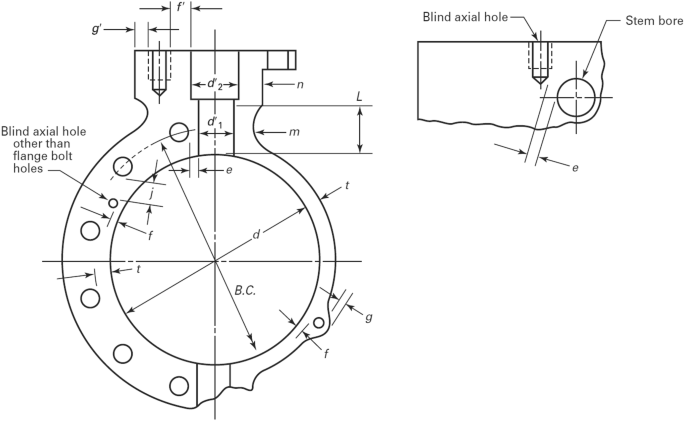
Butterfly valve body
-
(e)
The inner ligament (f and g in Fig. 6) for holes parallel to the body run should not be less than 0.25 \(t_{m,}\) but in no case less than 2.5 mm (0.1 in.). The sum of the inner and outer ligaments should not be less than \(t_{m}\).
-
(f)
A ligament within the minimum body wall between two adjacent holes within the minimum body valve (j in Fig. 6) should be 0.25 \(t_{m}\) or greater, but not less than 2.5 mm (1 in).

The minimum wall thickness of the valve \(t_{m}\) based on the valve pressure class and the internal diameter (d) can be calculated based on the equations shown in Table 2.
3 Case study
A ball valve supplier provided a compact wafer design for a ¾” Class 300 valve with a carbon steel body as shown in Fig. 7. The valve does not have any body flange and sits between two flanges in a way that flange bolts are drilled into the valve body. This design reduces the thickness of the valve on the points where the body of the valve has been drilled. The main concern is whether or not the design of the valve complies with ASME B16.34 standard. The minimum required wall thickness as per ASME B16.34 depends on the minimum bore of the valve [8]. Table 3 shows the relationship between the inside diameter of the valve in mm and the minimum wall thickness in mm [8].

Compact wafer design ball valves
The minimum bore of a ball valve based on a size can be obtained from the API 6D standard, Pipeline Valves [9]. Table 4 shows the minimum bore for a full opening valve based on the API 6D standard [9].
The minimum bore of a 3/4″ Class 300 ball valve as per Table 4 is 19 mm. As shown in Table 3, the minimum thicknesses of valves in Class 300, and minimum 18 mm and 21 mm internal diameters, are 3.3 mm and 3.5 mm, respectively. Using interpolation provides the minimum thickness of a 3.4 mm for a 19 mm internal bore ball valve in size ¾” and Class 300. However, Table 2 Eq. 1 on the first row provides a different result for the minimum thickness:
The carbon steel valve has a corrosion allowance (CA) equal to 3 mm to mitigate the risk of corrosion and metal loss. The 3 mm corrosion allowance as per NORSOK L-001 standard should be added to the minimum valve thickness, as per Eq. 2.
Note: \(t_{m}\) in the criteria, (c), (d), (e), and (f) will be considered the minimum wall thicknesses including the CA, which is equal to 6.9 mm.
Figure 8 shows the machining body drawing of the valve including the bolt holes. It is important to check and make sure that each section of the valve body has a higher thickness than the minimum thickness requirement and complies with the requirements of ASME B16.34 Sections (a) to (f).

Compact wafer valve body machining drawing
The internal bolt holes are based on ASME B.1.1, Cl. 2B coarse series UNC (Unified Nominal Coarse), which matches the flange bolting dimensional so that it satisfies the requirement in Section (a). The bolting depth in Fig. 8 is 24 mm and the size M12 is equal to 12 mm and they are threaded in the body. The bolting length is double the bolting size so this satisfies the requirement in Section (b).
Referring to the minimum thickness in Section (c) of ASME B16.34, the minimum thickness of the valve in Fig. 8 is \(C_{2} = 10.55\,{\text{mm}}\), \(A = 24\,{\text{mm}}\) and \(D_{2} = 13\,{\text{mm}}\). All three parameters are more than the minimum allowable thickness equal to 6.9 mm calculated based on Eq. 2, which qualifies the design regarding the minimum thickness and Section (c) of ASME B16.34.
The inner ligament (E in Fig. 8) should be less than 0.25\(t_{m}\) and greater than 0.25 mm.
Thus, the thickness of the inner ligament is sufficient and complies with the requirements of Section (d) of ASME B16.34.
The inner ligament for holes parallel to the body run should not be less than 0.25\(t_{m}\) but in no case less than 2.5 mm (0.1 in). The sum of the inner and outer ligaments should not be less than \(t_{m}\) as described in Section (e) of ASME B16.34. Two inner ligaments of \(C_{1}\) and \(C_{2}\), as well as \(D_{1}\) and \(D_{2}\) should be verified based on the previous criteria.
The next section of this paper verifies the minimum thickness in the closure part of the valve as per the machining drawing illustrated in Fig. 9.

Machining drawing of body closure
According to the minimum thickness in Section (c) of ASME B16.34, the minimum thickness of the valve in Fig. 9 is C2 = 10.55 mm, A = 9.5 mm and D2 = 9 mm. All three parameters are more than the minimum allowable thickness equal to 6.9 mm calculated based on Eq. 2, which qualifies the design regarding the minimum thickness and Section (c) of ASME B16.34.
The inner ligament for holes parallel to the body run should not be less than 0.25\(t_{m,}\) but in no case less than 2.5 mm (0.1 in). The sum of the inner and outer ligaments should not be less than \(t_{m}\) as described in Section (e) of ASME B16.34. Three ligaments of \(C_{1}\) and \(C_{2}\), \(C_{1}\) and \(D_{1}\), \(D_{1}\) and \(D_{2}\) should be verified based on the above criteria.
4 Conclusion
Flange connection is very common method of attaching a valve to a pipe. The flange is a ring-shaped device designed to be used as an alternative to welding or threading various piping components, including the valves. Alternatively, a wafer design is defined as a flangeless design with facing that permits installation between ASME and manufacturer-standard (MSS SP) flanges. The advantage of a wafer design over a flanged end design is that it saves face-to-face space, weight, and cost of the valve. This paper has presented a comparison of the valve face-to-face wafer type and double flange butterfly valves in class 150 and size ranges between 4″ and 20″ designed according to API 609. The use of wafer type butterfly valves as per API 609 is very common in the oil and gas industry. However, it is not common to use wafer type ball valves for weight and space saving. This paper reviews a case study of a wafer ball valve design including the flange bolt holes inside the body and the closure. The criteria in the ASME B16.34 standard regarding the minimum allowable wall thickness of the valve were used to verify this design.
References
Nayyar ML (2000) Piping handbook, 7th edn. McGraw-Hill Education, New York
Parisher RA, Rhea RA (2002) Pipe drafting and design, 2nd edn. Gulf Professional Publishing, Houston
Smit P, Zappe RW (2004) Valve selection handbook, 5th edn. Elsevier, New York
Skousen PL (2011) Valve handbook, 3rd edn. McGraw-Hill Education, New York
American Petroleum Institute 609 (2004) Butterfly valves: double flanged lug and wafer, 6th edn. API, Washington
Sotoodeh K (2018) Why are butterfly valves a good alternative to ball valves for utility services in the offshore industry?. Am J Ind Eng 5(1):36–40. https://doi.org/10.12691/ajie-5-1-6
Nesbitt B (2007) Handbook of valves and actuators: valves manual international, 1st edn. Elsevier, Oxford
American Society of Mechanical Engineers (ASME) (2004) Valves-flanged, threaded, and welding end. ASME B16.34, New York
American Petroleum Institute (API) (2014) Specification for pipeline and piping valves. API 6D, 24th edn. API, Washington
Author information
Authors and Affiliations
Corresponding author
Ethics declarations
Conflict of interest
The author(s) declare that they have no competing interests.
Additional information
Publisher's Note
Springer Nature remains neutral with regard to jurisdictional claims in published maps and institutional affiliations.
Rights and permissions
About this article

Cite this article
Sotoodeh, K. Wafer design valves verification based on ASME B16.34. SN Appl. Sci. 1, 1476 (2019). https://doi.org/10.1007/s42452-019-1344-0
Received:
Accepted:
Published:
DOI: https://doi.org/10.1007/s42452-019-1344-0