
Abstract
The development of multi-photon microscopic technique has made it possible to image submicron structures deep in biological tissues. This technique is widely used for imaging of cortical structures in developing and adult animals, and there have been detail descriptions of in vivo imaging of synaptic structures in normal animals through a thinned-skull or open-skull cranial window. However, several challenges should be considered carefully for high-resolution imaging of cortical structures under pathological conditions. Here we describe a protocol for in vivo imaging of dendritic structures following ischemic stroke through thinned skull. This protocol can also be applied for acute or chronic imaging of neuronal structural plasticity, glial activation, cerebral microcirculation, or synaptic functions in other pathological conditions.
INTRODUCTION
The invention of two-photon fluorescence microscopy enables direct visualization of submicron fluorescent structures deep in biological tissues with two-photon excitation (Denk et al. 1990). Excitation of fluorescent molecules based on simultaneous absorption of two photons of relatively longer wavelength has improved the imaging depth greatly. The application of two-photon microscopy to study synaptic plasticity in living animals has been facilitated with the emergence of transgenic mice expressing fluorescent proteins (Feng et al. 2000; Grutzendler et al. 2002; Trachtenberg et al. 2002). In the past decades, live imaging technique based on multi-photon excitation has been found widely applied in time-lapse observation of structural and functional changes of the nervous system during development and in a variety of disease models such as stroke, Alzheimer's disease, Parkinson's disease and spinal cord injury (Davalos et al. 2008; Eichhoff and Garaschuk 2011; Guo et al. 2015; Li and Murphy 2008; Reichenbach et al. 2018; Zhang et al. 2005; Zuo et al. 2005).
There have been detailed descriptions of the procedures for in vivo imaging of cortical structures in normal animals through thinned-skull or open-skull window (Grutzendler et al. 2011; Holtmaat et al. 2009; Yang et al. 2010; Zuo et al. 2013). However, these methods mainly focus on intravital microscopy of cortical structures in healthy animals, and pathological changes that may appear in disease models such as extravasation (leakage of blood plasma), inflammation, deformations of vascular structures are not emphasized. These pathological changes may affect refractive index of cortical tissues or increase technical difficulty which should be taken into consideration in high-resolution imaging.
Here, we describe a method for long-term in vivo imaging after ischemic stroke through thinned skull using two-photon microscopy. We discussed several technical challenges and expect this protocol to be useful for two-photon imaging of cortical structures and functions under various pathological conditions.
MATERIALS AND EQUIPMENT
Experimental animals
Transgenic mice expressing yellow fluorescent protein (YFP) in layer 5 pyramidal neurons (YFP H-line) and CX3CR1GFP/+ mice expressing green fluorescent protein (GFP) in microglia were purchased from the Jackson Laboratory and bred in animal facilities at School of Basic Medical Sciences, Lanzhou University. All the mice were kept on a 12-h light/12-h dark cycle at room temperature (22 ± 2 °C) and given free access to water and standard pellet diet. All animal experiments were approved and carried out in accordance with the institutional animal guidelines of Lanzhou University.
Reagents
5% ketamine hydrochloride (Gutian pharma, H35020148), xylazine (Sigma, X-1251), erythromycin eye ointment, glue (Alteco, 1214B), alcohol, povidone-iodine, Texas Red-dextran (Invitrogen, D-1830), NaCl, KCl, KH2PO4, Na2HPO4·12H2O, NaOH.
Equipment
Insulin syringe (Wego, U-100), thin-tipped forceps (Dumont, 0208-5-po), metal frame (homemade from two double-edged razor blades), dissecting microscope (Olympus, SZ61, Japan), custom-made steel plate (17 cm × 9 cm × 0.1 cm), surgical board (homemade, 23 cm × 14 cm × 1.5 cm), air duster (Sunto, 400 mL), high-speed dental drill (Fine Science Tools), microsurgical blade (Salvin Dental, BLAD-NORDLAND-69), feedback-regulated heating pad (Taimeng, JR-1/2), fluorescence microscope (Olympus, BX51, Japan), two-photon microscope (Olympus, FV1000, Japan), water immersion objective (Olympus, 25×, 1.05 numerical aperture (NA)).
Reagent setup
Saline (0.9% NaCl)
Dissolve 0.9 g of NaCl in 100 mL of sterile distilled water. The saline is filter-sterilized and then stored at 4 °C.
Anesthetics
Anesthesia is induced with a mixture of ketamine hydrochloride and xylazine (100 mg/kg ketamine and 15 mg/kg xylazine body weight). Dissolve 75 mg of xylazine in 10 mL of 5% ketamine hydrochloride, and then add sterile 0.9% NaCl to a total volume of 25 mL.
75% alcohol
Add 75 mL of 100% alcohol and then add sterile distilled water to bring the total volume to 100 mL. This solution is used for disinfection of all the surgical instruments and intact skin during surgery.
Phosphate buffered saline (PBS, pH 7.4)
Dissolve 0.2 g of KCl, 0.2 g of KH2PO4, 8 g of NaCl and 2.89 g of Na2HPO4·12H2O in 900 mL of distilled water. Adjust the pH to 7.4 with 1 mol/L NaOH. Bring the volume to 1 L, filter-sterilize with filter apparatus, and then store at 4 °C.
Texas Red-dextran (10 mg/mL)
Dissolve 1 mg of Texas Red-dextran in 100 µL of sterile PBS, and then store at 4 °C, protected from light.
SUMMARIZED PROCEDURE
-
(1)
Prepare surgical instruments and anesthetize the mouse.
-
(2)
Separate bilateral common carotid arteries and prepare thinned-skull cranial window for imaging.
-
(3)
Image dendritic and vascular structures before ischemia.
-
(4)
Establish ischemic stroke model by ligating bilateral common carotid arteries and image cortical structures during ischemia.
-
(5)
Reperfuse the blood vessels and image cortical structures at different time points after reperfusion.
-
(6)
Take care of the animal for long-term imaging and perform repeated imaging of cortical structures over days or weeks.
PROCEDURE
Preparation of surgical instruments
-
(1)
Prepare all the surgical instruments and tools, including high-speed dental drill, custom-made steel plate (Fig. 1A), scissors, scalpel, thin-tipped forceps, double-edged razor blade, glue, surgical sutures, and cotton threads. Make a metal frame by gluing two double-edged razor blades together.
Fig. 1 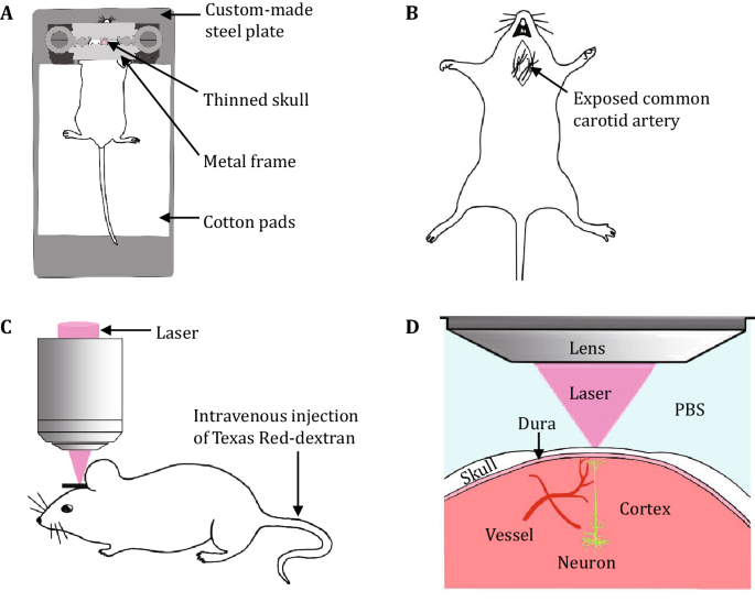
Schematic diagram showing the principal experimental steps of the protocol. A Surgery and optical window preparation. The diagram shows the fixation device for skull thinning and imaging. B Stroke induction through ligation of the bilateral common carotid arteries. C Labeling of brain vasculature through intravenous injection of Texas Red-dextran. D Two-photon in vivo imaging of cortical structures through the thinned skull
-
(2)
Sterilize the surgical instruments with 75% alcohol and then immerse the surgical instruments in the saline for later use.

Anesthetization of mouse
-
(3)
Weigh and deeply anesthetize the mouse with a mixture of ketamine hydrochloride and xylazine (5 µL/g body weight, intraperitoneal injection).
[CAUTION!] A small amount of anesthetics (~20 µL) can be supplemented when the mouse is waking up during experiment. However, overdose of supplementary anesthetics can lead to the death of mouse and should be avoided.
Surgery and separation of bilateral common carotid arteries
-
(4)
Cover the eyes of the mouse with erythromycin eye ointment to protect the eyes during surgical operation and imaging.
-
(5)
Place the mouse in the ventral supine position and immobilize the limbs of the mouse on a homemade surgical board with cotton threads. Shave the ventral neck using a razor blade and then disinfect the neck with 75% alcohol, and then make an incision along the midline in the ventral neck with a scalpel. Carefully separate and expose the bilateral common carotid arteries from carotid sheath using thin-tipped forceps without damaging the vagal nerves and blood vessels. Use scissors to cut four surgical sutures (~2 cm long each) and loosely encircle the bilateral common carotid arteries with surgical sutures (Fig. 1B). We suggest to place two surgical sutures under each common carotid artery so that the bilateral common carotid arteries can be tightly ligated during ischemia. Close the skin incision loosely with forceps, place the mouse in the prone position, and put a sterile and PBS-immersed cotton ball under the incision to prevent the tissue from drying out.
[Note] We suggest separating the bilateral common carotid arteries before preparing the optical window to avoid contamination or damage of the optical window.
Optical window preparation
-
(6)
Shave the hair on the head of the mouse using a double-edged razor blade, disinfect the scalp with 75% alcohol, and then make an incision along the midline of the scalp with a scalpel to expose the skull.
[CAUTION!] Do not apply 75% alcohol to open wounds or exposed skull.
-
(7)
Remove the soft tissue on the skull with thin-tipped forceps or microsurgical blade, glue the skull to a metal frame (made by gluing two double-edged razor blades together), and then fix the mouse to a custom-made steel plate (Fig. 1A).
[CRITICAL STEP] The soft tissue on the skull should be removed completely and the metal frame must be glued tightly to the skull instead of the scalp to avoid movements during imaging.
-
(8)
Thin the skull using a high-speed dental drill. Localize the area to be thinned and label it using a marker pen over the right somatosensory cortex at coordinates of −1.5 mm from bregma and 2.0 mm from the midline. Thin a ~2 mm × 2 mm area of skull (or a circular area with a diameter of ~2 mm) using a high-speed dental drill under the dissecting microscope until the surface blood vessels of the brain beneath the thinned skull is clearly visible.
[Note] In the literature, an imaging window of 200–300 μm in diameter is typically thinned for high-resolution two-photon in vivo imaging of cortical structures (Bhatt et al. 2009; Zuo et al. 2005). In ischemic condition, some of imaged regions are not suitable for imaging at the next imaging time point due to extravasation, inflammation and ischemic damage. Thus, we recommend preparing a relatively bigger imaging window and taking a few image stacks of different areas to increase the chances of successful multiple-time point imaging. However, extra care should be taken to avoid damage when thinning a large imaging window.
[CAUTION!] Skull thinning for young and adult mice is different. The skull of adult mouse (>3 months) is thick and hard, containing spongy bone layer. While the skull of young mouse (<2 months, especially for mouse less than 1-month-old) is thin and soft. Skull thinning for young mouse should be more careful. Mice with dendritic beading due to mechanical or thermal damage during surgical operation are not suitable for long-term imaging and should be replaced.
[CRITICAL STEP] Evenly thin the skull at one direction, blow away the skull scraps with an air duster, and wait for a while before continuing thinning the skull to avoid mechanical or thermal damage to cortical tissues. A drop of PBS can be applied to the thinned skull to avoid thermal damage during thinning.
-
(9)
When the thickness of the thinned skull is close to ~30–50 µm, carefully smooth the skull using a microsurgical blade at ~45° angle until the neuronal structures are evenly clear under microscope. The skull thickness is thinned to ~25 µm for the first imaging.
[Note] The thickness of the thinned skull can be estimated roughly by checking the clarity of the blood vessels through the thinned cranial window. To estimate the thickness of the thinned skull, add a drop of PBS to the surface of the thinned skull and check the clarity of the blood vessels through the thinned cranial window under the dissecting microscope. The blood vessels appear blurred when the skull is thick (>50 µm) and it will become very clear when the skull is thinned to ~30 µm (Fig. 2). The thickness of the thinned skull can be measured accurately via second harmonic generation imaging. The skull can generate second harmonic light and this signal can be used to measure the thickness of the skull. We suggest the two-photon microscope equipped with a filter set that can collect this signal (in our case, a 380–560 nm barrier filter is used to collect the second harmonic generation signal and YFP signal).
Fig. 2 
Estimating the thickness of thinned skull by checking the clarity of the blood vessels under the dissecting microscope. A, B Images of blood vessels when the skull is 55 µm before and after adding PBS, respectively. The blood vessels (arrow) in A are barely visible when the thickness of the thinned skull is 55 µm before adding PBS, and the blood vessels (arrow) in B are visible but remain blurred after adding a drop of PBS on the thinned skull. C, D Images of blood vessels under the dissecting microscope when the skull is thinned to 30 µm before and after adding PBS, respectively. The arrows in C and D indicate the same blood vessels as shown in A and B. Note the image of blood vessels in C is much clearer than that in A, and the image in D is much clearer than that in B. The thickness of the skull is confirmed by second harmonic generation imaging (data not shown)
[CRITICAL STEP] Tune the Ti:sapphire laser to 920 nm. When the surface blood vessels start to become clear, measure the thickness of the skull via second harmonic generation signal under two-photon microscope during the thinning process. A Z-stack image of the thinned skull is collected with a step size of 1 µm and the thickness of skull is measured by calculating the distance from the top surface to the bottom layer of the thinned skull. In order to achieve high-quality repeated images avoid unnecessary thinning of the skull for the first imaging time point, so that the skull can be thinned again to ~20 µm or even thinner for the second and third imaging time points.

Imaging of cortical vasculature with a CCD camera
-
(10)
For repeated imaging, select a properly thinned area and locate a region of interest with clear neuronal structures. Image the superficial vasculature of the cortex over the thinned area with a charge coupled device (CCD) camera (Olympus, DP72, Japan) equipped to the fluorescence microscope. The vasculature structure can be used as landmarks for repeated imaging of the same area at later time points (alternatively, a sketch of the vasculature structure can be hand-drawn under the dissecting microscope).
Transcranial two-photon imaging of cortical structures before ischemia
-
(11)
Fit the animal into an Olympus FV1000 two-photon microscope. Tune the Ti:sapphire laser to 920 nm for YFP excitation.
-
(12)
Intravenously inject 20 µL of Texas Red-dextran (10 mg/mL in PBS) (Fig. 1C).
-
(13)
Examine the vasculature and dendrites under the fluorescence microscope. Select a region of interest with clear structures of dendrites and vessels at the thinned area for imaging.
-
(14)
Transcranially image the neuronal and vascular structures using a water immersion objective (25×, 1.05 NA) (Fig. 1D). Measure blood flow velocity by repeated line scanning of an arteriole or a capillary before ischemia (Fig. 3A, B). Collect a Z-series of 20 to 30 optical sections (1024 × 1024 pixel arrays) with zoom 1 and a step size of 1 µm, and this low magnification image stack can be used for locating fine neuronal structures in the following steps. The laser intensity is adjusted during imaging to get a clear image of the dendrites but avoid over saturation of the dendrites.
Fig. 3 
In vivo imaging of dendritic structures and cortical microcirculation. A Two-photon images showing blood vessels (red) labeled with Texas Red-dextran and dendritic structures (green) before ischemia, during ischemia, and after reperfusion. Note that the leakage of blood plasma (arrowhead) nears the vessel during ischemia. B Line scanning images monitoring microcirculation in a vessel labeled in A (arrow) before ischemia, during ischemia, and after reperfusion. C Magnified view of the yellow-boxed region in A showing spine plasticity following ischemic stroke. Asterisks indicate filopodia, arrowheads show a stable spine during ischemia/reperfusion, open arrowheads show a spine lost after ischemia and reperfusion, chevrons show a spine disappeared during ischemia and then re-appeared after reperfusion, and arrows show a new spine formed after reperfusion
[Note] If the image of dendrites and spines is not clear, thin the skull using high-speed drill or microsurgical blade again. Carefully and evenly thin the skull with a microsurgical blade if the skull is uneven. Blow away the skull scraps with an air duster. Replace the PBS between the skull and the objective with fresh PBS if any blood or skull scraps accumulated in PBS.

-
(15)
Collect Z-series of 40 to 60 optical sections (1024 × 1024 pixel arrays) of 3–5 different areas within the region of interest with zoom 4 and a step size of 0.75 µm (Fig. 3C).
[Note] We recommend taking a few image stacks of different areas in the region of interest in case some of the imaged areas are not suitable for imaging at next imaging time point due to inflammation, and neuronal damage following ischemia. In addition, as subsequent ischemia will induce marked leakage of blood plasma, which will greatly affect the image quality of dendritic structures, we suggest avoid imaging those areas which are too close to the large blood vessels.
Reversible cerebral ischemia model using bilateral common carotid artery ligation (BCAL) and in vivo imaging
-
(16)
Take down the mouse from the microscope stage. Place the mouse in the ventral supine position.
-
(17)
Expose the bilateral common carotid arteries again and tighten the surgical sutures around the bilateral common carotid arteries to induce ischemia under the dissecting microscope.
[Note] Tighten the sutures using a slipknot so that the surgical sutures can be easily untied during reperfusion. Ligate each common carotid artery with two surgical sutures so that the bilateral common carotid arteries are ligated tightly and ensure no gap and blood between the two sutures to avoid thrombosis.
-
(18)
Put the mouse back under the microscope and find the same imaged area based on the landmark vasculature structure described at Step 10.
[CAUTION!] It is difficult to find the same imaged area due to deformation of blood vessels and damage of neuronal structures after ischemia. Try to put the mouse back under the microscope as soon as possible before severe dendritic beadings occur, and find the same dendrites by the relative location of blood vessel and the dendrite after the bilateral common carotid arteries are ligated.
-
(19)
Measure the reduction of blood flow velocity during ischemia by repeated line scanning (Fig. 3A, B), and evaluate damages of dendritic structures during ischemia by fast scanning. BCAL model is considered successful when significant reduction in blood flow (>90% reduction) and dendritic beadings are observed within 10 min after BCAL.
-
(20)
The animals are subjected to ischemia for 30 min, and an image stack in each imaged area described at Step 15 is collected during ischemia using zoom 4 to monitor the dynamic changes of dendritic structures (Fig. 3C).
[CAUTION!] Leakage of blood plasma and pH change induced by ischemia will greatly reduce the YFP signal, adjust laser intensity accordingly to get a clear image of dendritic structures. Try to avoid those dendrites which are too close to the large blood vessels for imaging and further analysis.
-
(21)
Take down the mouse from the microscope again and untie the surgical sutures to reperfuse the blood vessels under the dissecting microscope.
[CAUTION!] Slowly untie the surgical sutures to reperfuse the blood vessels and carry out chest compressions to help the mouse restore blood circulation. Sudden reperfusion after long period of ischemia could induce abnormal heartbeat or breathing.
-
(22)
Put the mouse back under the microscope again, find the same image area based on the vasculature structure, and measure the blood flow velocity after reperfusion by repeated line scanning.
-
(23)
Take an image stack of the dendritic and spine structures using zoom 4 at different time points after reperfusion. Body fluid is maintained by intraperitoneal injection of saline at 1–2 h intervals during imaging.
Animal care after imaging
-
(24)
After imaging, take down the mouse from the steel plate. Remove the residual glue on the skull and scalp, thoroughly clean the skin incision and clean away debris and blood clots using 0.9% NaCl to prevent infections. Suture the skin incision in the neck and head with sterile surgical sutures. Note that the suture of skin incision should be neither too tight nor too loose. Disinfect the skin of the neck and head with povidone-iodine.
-
(25)
Maintain the animal’s body temperature at 37 ± 0.5 °C using a heating pad (Taimeng, JR-1/2) until the mouse has fully recovered from anesthesia. Body fluid is maintained by intraperitoneal injection of saline at 1–2 h intervals before awakening from anesthesia.
-
(26)
Put the mouse into a separate cage after recovering from anesthesia. The mouse will be less active due to ischemia. Liquid diet can be provided if necessary. The animal was housed for different time periods of long-term in vivo imaging.
[CAUTION!] Feed the mouse separately in avoidance of interference by other mice, and monitor the animal every day. To keep the animal warm, some soft cotton can be put into the cage for bedding.
Repeated imaging of cortical structures over days or weeks
-
(27)
Repeated imaging is performed at fixed time point (e.g., 3 days or 7 days) after the first imaging. Anesthetize the mouse with a mixture of ketamine hydrochloride and xylazine as described at Step 3.
-
(28)
Untie sutures of the head skin incision, clean the skull and glue the skull to the metal frame as described at Step 7.
[CAUTION!] Avoid spreading the glue onto the thinned area.
-
(29)
Locate the previously thinned region under the dissecting microscope based on the superficial vasculature of the cortex.
[Note] Some small vessels may be greatly deformed or even disappear after ischemia. Large vessels are relatively stable and some of them can still be used as reference landmarks.
-
(30)
Carefully remove newly grown bone layer with a dental drill and smooth the skull with a microsurgical blade until the optical window is clear. Examine the neuronal structures under a fluorescence microscope and keep thinning the skull until a clear image is obtained. The skull thickness is thinned to ~20 µm for the second imaging.
[CAUTION!] Avoid unnecessary thinning of the skull. A drop of PBS on the skull may help check the clarity of the optical window and reduce the thermal damage. If the second imaging is performed within 3 days after the first imaging, the skull is just needed to be slightly thinned using a microsurgical blade. If the second imaging is performed after a longer time interval (e.g., at 7 days) after reperfusion, the newly grown bone needs to be thinned with a drill and then smoothed with a microsurgical blade.
-
(31)
Find the previously imaged region of interest under the fluorescence microscope by locating the landmark blood vessels.
[Note] Some of the small vessels may disappear after ischemic stroke, but large blood vessels are relatively stable and the previously imaged region of interest can be located based on the remaining large landmark blood vessels.
-
(32)
Find the previously imaged neuronal structures in the region of interest.
[Note] Some of the previously imaged neuronal structures may become blurred due to ischemic damage or inflammation, and only the areas with clear dendritic structures can be used. The low magnification image stack collected with zoom 1 at Step 14 can be used as a reference for locating the same dendritic structures.
-
(33)
Repeat Step 23 for in vivo imaging again.
-
(34)
Perform animal care as described at Steps 24–26.
-
(35)
The third imaging is performed at 14 or 30 days after ischemic stroke. Repeat Steps 27–29. Thin the skull carefully using a dental drill and smooth the skull with a microsurgical blade. The skull is thinned to ~15 µm for the third imaging. Repeat Step 23 for two-photon in vivo imaging again.
[CRITICAL STEP] The skull thinning for the third imaging should be carefully performed because the skull is already very thin. Carefully drill the newly grown bone, and then scrape and smooth the skull using a microsurgical blade. Avoid unnecessary thinning of the skull.
[Note] A drop of PBS can be applied to the thinned skull to help check the thickness of the bone during thinning as demonstrated in Fig. 2. The PBS is removed using a sterile cotton swab and dried with an air duster before further thinning.
-
(36)
Sacrifice the animal or perform animal care as described at Steps 24–26 for further imaging if necessary.
DISCUSSION
Two-photon microscopy has become a powerful tool for studying structural and functional changes in living animals. Here, we introduce a protocol for long-term two-photon in vivo imaging of cortical structures after ischemic stroke and highlight the critical steps that need special attention for repeated imaging of dendritic structures under pathological condition. We have successfully applied this protocol to monitor real-time blood flow velocity (Fig. 3), and achieved high-resolution images of the same dendritic structures over 30 days following ischemic stroke (Fig. 4). This experimental approach is particularly suitable for time-lapse imaging of acute or chronic effects of pathological insults on microcirculation and neuronal structural plasticity (Ju et al. 2018; Zhu et al. 2017). In addition, we have also successfully applied this protocol to monitor microglial response following ischemic stroke using CX3CR1GFP/+ mice expressing GFPs in the microglia (Fig. 5) and hope this method can also be applied to some other disease models.

Repeated imaging of dendritic structures before and after ischemic stroke. The same dendritic structures are imaged before and after ischemia/reperfusion. Arrowheads, arrows and open arrowheads show a stable spine, a newly formed spine and an eliminated spine after ischemia/reperfusion, respectively. Note that a spine (chevrons) disappeared after ischemia and at 1 h after reperfusion, but re-appeared at 3 days after reperfusion and remained stable at 30 days after reperfusion

Repeated imaging of microglia response to cerebral ischemia. A Microglia exhibit highly ramified morphology before ischemia. B Microglia remain highly branched at 1 h after ligating the bilateral common carotid arteries. C Microglia retract most processes at 1 day after reperfusion. D Microglia transform into amoeboid phenotype at 3 days after reperfusion. Arrows indicate the same microglia at different time points, and all the images are XY maximal projections (20 μm in depth) from the same CX3CR1GFP/+ mice captured before or after ischemia/reperfusion
Imaging through the thinned skull is a minimally invasive technique and does not involve time-consuming preparation of open-skull glass window (Garre et al. 2017; Xu et al. 2007; Yang et al. 2010). However, mastering the skill of thinning high-quality skull window also needs days or even weeks of practice. The preparation of thinned-skull window is critical for the visualization of submicron structures deep in living brain tissue. The fluorescence intensity drops sharply as the skull thickness increases (Zuo et al. 2005). We suggest thinning the skull to ~25 µm for the first imaging time point to achieve reasonable quality of image. Thinner skull can improve the fluorescence signal, but on the other hand, it can increase the risk of tissue damage. For acute or single-time-point imaging, skull can be thinned to ~15 µm. However, the skull can be only thinned for a limited number of times. Thus, for repeated imaging, try to avoid unnecessary thinning of the skull so that the skull can be thinned again at later imaging sessions. The protocol described here can be used to achieve repeated imaging at least 4 times through thinned skull. In our experience, both open-skull and thinned-skull window can be used for in vivo imaging of cortical structures following ischemic stroke. Although our protocol is mainly based on imaging through thinned-skull window, similar imaging procedures and cautions are also applicable to imaging through open-skull window. In addition, we believe open-skull window is valuable for imaging of cortical structures especially when pharmacological intervention needs to be applied to the exposed cortex. However, since open-skull surgery can cause acute inflammatory response and glial activation (Xu et al. 2007), chronic imaging through the open-skull window is suggested only after the animal recovers from open-skull surgery (at least 2 weeks after open-skull window).
Repeated imaging of cortical structures through the thinned-skull preparation under pathological conditions faces several technical challenges. One challenge is that it is difficult to locate the previously imaged area due to deformation or damage of cortical structures. The blood vasculature or neuronal structures may change drastically after ischemia, and some previously imaged structures may even disappear with pathological progression of the disease. However, the same imaged area can still be located based on the residual large blood vessels. In addition, dendritic branches are relatively stable and a low magnification image of the dendritic structures is strongly recommended to ensure locating the same structures at later time points. Another challenge is that various factors such as leakage of blood plasma, tissue damage, inflammation, and pH change under pathological conditions can greatly change the refractive index and therefore affect image quality. These factors may produce artifactual effects on the plasticity of cortical structures and should be considered carefully for repeated imaging. For example, a decrease in pH during ischemia may cause quenching of fluorescent signals, leading to an overestimation of spine dynamics (Zhu et al. 2017). It is also quite a challenge to take care of animals under pathological conditions. An imaging session in a healthy animal normally takes 1–2 h. However, an imaging session in an ischemia model may last 3–5 h. Proper animal care can greatly increase the survival rate of the animals and reduce artifactual changes of cortical structures.
References
Bhatt DH, Zhang S, Gan WB (2009) Dendritic spine dynamics. Annu Rev Physiol 71:261–282
Davalos D, Lee JK, Smith WB, Brinkman B, Ellisman MH, Zheng B, Akassoglou K (2008) Stable in vivo imaging of densely populated glia, axons and blood vessels in the mouse spinal cord using two-photon microscopy. J Neurosci Methods 169:1–7
Denk W, Strickler JH, Webb WW (1990) Two-photon laser scanning fluorescence microscopy. Science 248:73–76
Eichhoff G, Garaschuk O (2011) Two-photon imaging of neural networks in a mouse model of Alzheimer's disease. Cold Spring Harb Protoc 2011:1206–1216
Feng G, Mellor RH, Bernstein M, Keller-Peck C, Nguyen QT, Wallace M, Nerbonne JM, Lichtman JW, Sanes JR (2000) Imaging neuronal subsets in transgenic mice expressing multiple spectral variants of GFP. Neuron 28:41–51
Garre JM, Silva HM, Lafaille JJ, Yang G (2017) CX3CR1(+) monocytes modulate learning and learning-dependent dendritic spine remodeling via TNF-alpha. Nat Med 23:714–722
Grutzendler J, Kasthuri N, Gan WB (2002) Long-term dendritic spine stability in the adult cortex. Nature 420:812–816
Grutzendler J, Yang G, Pan F, Parkhurst CN, Gan WB (2011) Transcranial two-photon imaging of the living mouse brain. Cold Spring Harb Protoc 2011:pdb-prot065474
Guo L, Xiong H, Kim JI, Wu YW, Lalchandani RR, Cui Y, Shu Y, Xu T, Ding JB (2015) Dynamic rewiring of neural circuits in the motor cortex in mouse models of Parkinson's disease. Nat Neurosci 18:1299–1309
Holtmaat A, Bonhoeffer T, Chow DK, Chuckowree J, De Paola V, Hofer SB, Hubener M, Keck T, Knott G, Lee WC, Mostany R, Mrsic-Flogel TD, Nedivi E, Portera-Cailliau C, Svoboda K, Trachtenberg JT, Wilbrecht L (2009) Long-term, high-resolution imaging in the mouse neocortex through a chronic cranial window. Nat Protoc 4:1128–1144
Ju F, Ran Y, Zhu L, Cheng X, Gao H, Xi X, Yang Z, Zhang S (2018) Increased BBB permeability enhances activation of microglia and exacerbates loss of dendritic spines after transient global cerebral ischemia. Front Cell Neurosci 12:236
Li P, Murphy TH (2008) Two-photon imaging during prolonged middle cerebral artery occlusion in mice reveals recovery of dendritic structure after reperfusion. J Neurosci 28:11970–11979
Reichenbach N, Delekate A, Breithausen B, Keppler K, Poll S, Schulte T, Peter J, Plescher M, Hansen JN, Blank N, Keller A, Fuhrmann M, Henneberger C, Halle A, Petzold GC (2018) P2Y1 receptor blockade normalizes network dysfunction and cognition in an Alzheimer's disease model. J Exp Med 215:1649–1663
Trachtenberg JT, Chen BE, Knott GW, Feng G, Sanes JR, Welker E, Svoboda K (2002) Long-term in vivo imaging of experience-dependent synaptic plasticity in adult cortex. Nature 420:788–794
Xu HT, Pan F, Yang G, Gan WB (2007) Choice of cranial window type for in vivo imaging affects dendritic spine turnover in the cortex. Nat Neurosci 10:549–551
Yang G, Pan F, Parkhurst CN, Grutzendler J, Gan WB (2010) Thinned-skull cranial window technique for long-term imaging of the cortex in live mice. Nat Protoc 5:201–208
Zhang S, Boyd J, Delaney K, Murphy TH (2005) Rapid reversible changes in dendritic spine structure in vivo gated by the degree of ischemia. J Neurosci 25:5333–5338
Zhu L, Wang L, Ju F, Ran Y, Wang C, Zhang S (2017) Transient global cerebral ischemia induces rapid and sustained reorganization of synaptic structures. J Cereb Blood Flow Metab 37:2756–2767
Zuo Y, Lin A, Chang P, Gan WB (2005) Development of long-term dendritic spine stability in diverse regions of cerebral cortex. Neuron 46:181–189
Zuo Y, Yu X, Tennant K, Jones T (2013) In vivo imaging of synapse plasticity in the mouse motor cortex. Methods Mol Biol 1010:45–57
Acknowledgements
This work is supported by grants from the National Natural Science Foundation of China (81771324).
Author information
Authors and Affiliations
Corresponding author
Ethics declarations
Conflict of interest
Lei Wang, Lirui Zhu, Junru Liu, and Shengxiang Zhang declare that they have no conflict of interest.
Human and animal rights and informed consent
All institutional and national guidelines for the care and use of laboratory animals were followed.
Rights and permissions
Open Access This article is licensed under a Creative Commons Attribution 4.0 International License, which permits use, sharing, adaptation, distribution and reproduction in any medium or format, as long as you give appropriate credit to the original author(s) and the source, provide a link to the Creative Commons licence, and indicate if changes were made. The images or other third party material in this article are included in the article's Creative Commons licence, unless indicated otherwise in a credit line to the material. If material is not included in the article's Creative Commons licence and your intended use is not permitted by statutory regulation or exceeds the permitted use, you will need to obtain permission directly from the copyright holder. To view a copy of this licence, visit http://creativecommons.org/licenses/by/4.0/.
About this article

Cite this article
Wang, L., Zhu, L., Liu, J. et al. Long-term high-resolution in vivo imaging of cerebral cortical structures following ischemic stroke. Biophys Rep 6, 127–136 (2020). https://doi.org/10.1007/s41048-020-00105-y
Received:
Accepted:
Published:
Issue Date:
DOI: https://doi.org/10.1007/s41048-020-00105-y