
Abstract
Purpose
Fluorapatite (Fap), an alumina (Al2O3) known for its excellent bio-inertia, can significantly increase the biocompatibility and bioactivity of biomaterials. This study is an investigation of the interface bone/Al2O3–Fap composite coatings implanted in the tibia of the rabbit.
Methods
Two techniques T1 and T2 were implemented on four rabbits, R1–R4 to assess the effect of the alumina (Al2O3)–Fap [Ca10(PO4)6F2] composite, coating for 316L stainless steel, on bone contact. The fluorapatite powder was synthesized using a wet-chemical method. The biocompatibility and the bioactivity of the Al2O3–Fap composite were evaluated by in vitro/in vivo tests. The characteristics of the bone/implant interface were investigated with scanning electron microscopy, radiology and 3D scanner.
Results
The results showed that T2 was more effective than T1, with a good contact between the implant/bone on the radiographs performed after 28 days. Implants coated with alumina did not show any integration signs with bone tissue. The addition of Fap to alumina coating would increase the adhesion of prosthesis on bone cells and guarantee a stable implantation.
Conclusion
Al2O3–Fap coating showed excellent behavior in vitro and in vivo tests revealing that the Fap is effective in improving biocompatibility and bioactivity.
1 Introduction
Present research on new materials in the orthopedic field requires “In Vitro” and “In Vivo” tests conducted on animals in order to evaluate the adhesion between the implant and the bone tissue. This assessment depends on implants placing method and materials composition and bioactivity.
Brånemark et al. [1] define bone integration as direct, structural and functional contact between a living and organized bone and the surface of an implant bearing a load. The parameters necessary to obtain good osseo-integration are the biocompatibility, the shape and the surface state of the implant, the nature of the bone recipient site, the surgical technique and the loading conditions.
To begin with, the study of the interface between prosthetic implants and bone tissue is very important to know the quality of adhesion providing its behavior over time.
To begin with, the study of the interface between prosthetic implants and bone tissue is very important to know the quality of adhesion providing its behavior over time.
The prosthesis implantation technique must be simple and easily reproducible in order to have reliable results during animal experiments. On the other hand, the choice of materials is essential. These materials are intended for various biomedical applications. Alumina is a bio-ceramic used because of its mechanical and thermal performances. However, it does not stimulate bone integration because of its bio-inertia [2, 3]. The calcium phosphates are the most used bio-ceramics in bone or dental surgery because of their similar chemical composition to the bone tissue [4]. Fluorapatite (Fap) and hydroxyapatite (Hap) belong to this large family. Fap attracted attention as an alternative to pure Hap coatings on metallic implants for the similarity in its chemical composition with that of the bone mineral [4]. However, Hap materials did not prove to be the perfect solution. Indeed, Baltag et al. reported that the high degradation rate of Hap coatings in biological environments was a serious source of concern [5]. Furthermore, Hap showed some feebleness in its mechanical properties [6].
For this reason, a considerable amount of research turned to the investigation of Fap as an alternative solution [7]. The Fap was considered a potential replacement given its chemical and thermal stability [8]. The fluorite contained in Fap had a great influence on the physical and biological properties of materials [9]. In this work, the optimum fluorite content in Fap was fixed at 6.68 wt% corresponding to 1% fluor [10]. To benefit from these interesting properties, the Fap will be added to the alumina. Then, the mixtures will be projected into a metal substrate made of 316L stainless steel using the suspension high velocity oxy-fuel (SHVOF) thermal spraying method.
Nevertheless, the major problem with implants remains the uncertainty about the interfacial interaction between the prosthesis and the surrounding tissues.
Hence, the main objective of this work was to optimize the composition and the amount of the materials used for the implants so that they benefit from the advantages of Fap and Hap as additives to alumina. This study attempted to assess the biocompatibility and bioactivity of alumina–Fap composite coating, using in vitro and in vivo tests.
Secondly, the prothesis implantation technique must be simple and easily reproducible in order to have reliable results during animal experiments, as well as the implant placing method.
For this reason, this work purported a no less important objective aiming to assess the implantation technique in vitro and in vivo, using the rabbit. The ultimate purpose would be to enhance the biocompatibility and bioactivity of alumina–Fap composite coating in implants and to guarantee higher chances for implants success through the improvement of the implant techniques.
2 Materials and Methods
We evaluated the placement of four coated prostheses in four rabbits (R1–R4). The implants in R1 and R2 were coated with alumina while those in R3 and R4 were coated with a mixture of alumina–Fap. The added fluorine “F” was about 1%. Table 1 shows the two implantation techniques used in this study. The preparation and the sterilization of prostheses were the same for the four rabbits.
2.1 The Main Materials
The used Fap was synthesized by wet method [11, 12] in the Industrial Chemistry Laboratory at the National Engineering School of Sfax, Tunisia. Alumina (Al2O3), reference E-266 and having a purity exceeding 99%, is a powder bought from “Saint-Gobain” Company, France. Particle size is between 0.8 and 7 μm.
The simulated body fluid (SBF) which has the ionic concentrations very similar to those of human plasma was used to study the bioactive behavior of samples. For this, a commonly used SBF solution of pH 7.4 was prepared according to the procedure recently described by Kokubo and Takadama [13]. Table 2 presents the ionic composition of the supersaturated solution as-prepared SBF and the human blood plasma. The Al2O3 and Al2O3–Fap coatings were cut in parallelepipedic pieces of size 2 × 6 × 2 mm and then cleaned before being immersed in 100 mL of SBF. The temperature was maintained at 37 °C.
The phase compositions of the coated samples were examined with an X-ray diffractometer (PHILIPS PANALYTICAL) and with a scanning electron microscope (JEOL JSM 5800LV).
2.2 Preparation and Sterilization of the Prostheses
Figure 1 shows the shape and dimensions of prostheses. They were carefully chosen after several graft tests in order to perfectly fit in the medullary canal of the rabbit tibia.

Photos of the adopted rod for implantation: great diameter 5 mm, small diameter 4 mm, conicity 30° and length 37 mm
The best suitable stem for implantation was made of steel and had a large diameter of 5 mm, a small diameter of 4 mm, a conicity of 30° and a length of 37 mm.
The designed stems were coated with Al2O3–Fap composites using high velocity oxy fuel “SHVOF” flame-type thermal spraying to obtain nano-structured coatings with improved properties. This process was adopted in this study because it was already reported by [14, 15] that it was successfully used to develop biomedical applications. The combustion torch was manufactured by “Sulzer-Meteoa” Company.
The operating principle of this device can be divided into four phases [16]:
Generation of the heat source: high-intensity electric arc is created between two electrodes of the plasma torch to ionize gases and create plasma.
Injection of a liquid containing powder suspended by a metal injector in which the carrier gas circulates.
Interaction between powder particles and flame. The molten powder is conveyed at high speed to the substratum.
Spreading and solidification of particles on the substratum. The stack of particles forms the coating.
The thermal sprayed process parameters are listed in Table 3. The coating thickness was evaluated using a micrometer (200 μm).
Suspensions thermal spraying with flame on metallic substrates was carried out in the “LERMPS” Laboratory in France.
Figure 2 shows the different stages of the suspension thermal projection of the prostheses. Implants were subsequently sterilized by gamma irradiation using CO60 (Equinox, UK) before implantation.

Photos of the plasma spaying process: the red flame contains powder particles

a Preparation step, b local anesthesia of the rabbit, c staining of the leg and knee and d protection of the zone to be operated by a sterile sheet
2.3 Surgical Technique
For an “In Vivo” study in rabbits, the prosthesis implantation was carried out in a Laboratory of Animal Experimentation approved by the Faculty of Medicine of Sfax and by the Ethical Committee of the Habib-Bourguiba University Hospital, Tunisia. The surgical operation was performed on the rabbits, by an appropriate medical team with respect for all the protocols left of asepsis.
2.4 Animal Preparation and Anesthesia
Four adult white rabbits R1–R4 aged from 5 to 10 months, were used for the experiments. All surgical procedures were done under strict aseptic protocol. The animals were premedicated and anaesthetized with xylasine/ketamine mixture (10 mg/kg). The animal hind leg tibialis anterior face was shaved. After the injection, the animal was left at rest with eyes closed for about 20 min. The skin was disinfected with a povidone–iodine solution 10% (Betadine, Medapharma). Local anesthesia (Unicaine 2%) was employed in the anterior tibialis face. Each animal received a 37 mm long cylindrical bar of 4–5 mm diameter like the ones shown in Fig. 1. Surgical preparations for the cylinders were done using first a pilot drill and then a 2 mm twist drill. Careful drilling was done with a low rotary hand piece. The skin was sutured with interrupted threaded sutures. Skin was again soaked with povidone solution. After 28 days, the rabbits were sacrificed and the implants extracted. The samples were stored in a formalin-based solution called BB’S and then included in methacrylic resin to be used for radiological testing of bone tissue. X-ray radiography was performed using a Faxitron X-ray system (Edimex, Angers, France) equipped with a camera (5 × 5 CCD) as shown in Fig. 3.
Two different techniques of implantation were used:
Figure 4 illustrates technique one (T1). It was performed on R2 and R3 to implant the prostheses in the diaphyseal medium. The tibia was exposed by adopting an internal approach of the leg. Then, a diaphyseal bone segment of about 1 cm in length was resected. The diaphyseal canal was prepared with an adapted package to the size of the implant in order to facilitate its introduction. The final step was the introduction of the implant in the medullary and the closure of the skin.
Fig. 4 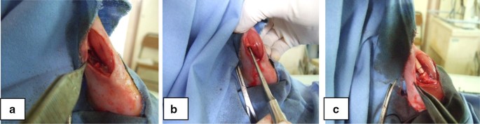
Implantation steps with the first technique (T1): a internal incision and resection of a 1 cm-segment of the tibial diaphysis, b preparation of the diaphysis before implantation and c inserting the prosthesis in place
Figure 5 illustrates the second technique (T2). It was applied to R1 and R4 to implant the prosthesis in metaphyso-diaphyseal zone. The knee was approached from the anterior side, going from the kneecap point to the anterior tibial tuberosity (ATT). An opening similar to that for introducing an intramedullary nail was performed through the patellar tendon to expose the anterior part of the upper tibial metaphysis. The knee was flexed by an operating aid and maintained at 130° to facilitate the exposure of ATT. Then, a bone perforation was conducted using a drill with the adequate diameter of the implant. Finally, the opening of the hole was enlarged and, the prosthesis was inserted using a hammer. Meanwhile, the knee was maximally flexed, until the bone substitute exactly fitted its place inside the bone. Before closing the skin using nylon nonabsorbable sutures, the full mobility of the knee was checked.
Fig. 5 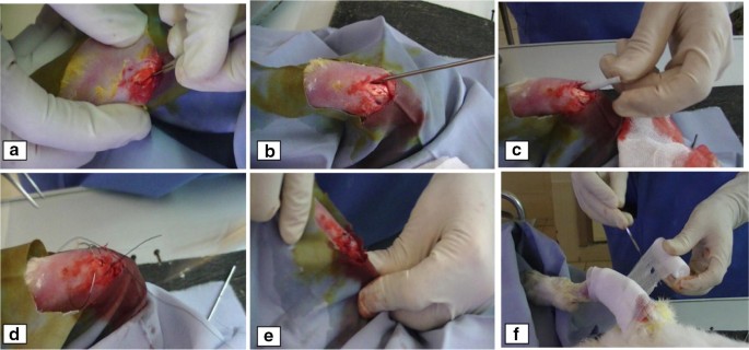
Implantation steps with the second technique (T2): a anterior incision of the knee, b perforation of the bone, c implant introduction, d skin closure, e verifying the mobility of the knee and f bandage


3 Results
3.1 In Vitro Tests
The compatibility of the alumina and the alumina–Fap composite coatings were evaluated by immersing the samples in SBF after 28 days.
As can be clearly seen in Fig. 6, pure alumina is an inert material that can neither initiate an apatite formation nor attach to the bone.

a SEM image of Al2O3 surfaces before immersion in SBF and b SEM image of Al2O3 surfaces after 28 days of immersion in SBF
Spherical shaped particles are observed on the surface of the coated material after 3, 7 and 28 days of immersion in SBF. Hence, this can be interpreted with much certainty as an indication of new crystals formation on the Fap phase of the composite. As the immersion time increases, the crystals grow in size and form an apatite layer as shown in Fig. 7. This layer appears to consist of many nano-sized crystallites with a spherical morphology, as observed by other authors [17].

a SEM image of Al2O3/Fap with 1 wt% F composite surfaces before immersion in SBF, b SEM image of Al2O3/Fap with 1 wt% F composite surfaces after 3 days of immersion in SBF, c SEM image of Al2O3/Fap with 1 wt% F composite surfaces after 7 days of immersion in SBF and d SEM image of Al2O3/Fap with 1 wt% F composite surfaces after 28 days of immersion in SBF
Figure 8 shows a cross-section view of the Al2O3/Fap composite after 28 days of immersion in SBF. It confirms the presence of a thin apatite layer of 5. 62 ± 0.1 µm on the composite surface. According to Kokubo and Takadama [13], the bone-bonding ability of a material depends on the ability of apatite to form on its surface when immersed in SBF. This work revealed that the incorporation of 1 wt% of Fap into alumina could promote the apatite layer formation on the coating surface when soaked in SBF. Therefore, it can be concluded that, similarly to bioactive ceramics, an Al2O3–Fap composite coating could achieve bone-bonding.

a SEM images of Al2O3/Fap composite surfaces cross-section before 28 days of immersion in SBF and b SEM images of Al2O3/Fap composite surfaces cross-section after 28 days of immersion in SBF
Figure 9 presents the XRD patterns of SHVOF Al2O3–Fap with 1 wt% F composite coating in function of immersing time in SBF. After each immersion in SBF, the examination of the coating surface shows a modest modification of the peak shapes of the Fap phase in the composite, indicating the presence of phase transition that depends on the immersion time.

XRD patterns of SHVOF Al2O3–Fap with 1 wt% F composite coating in function of immersion time in SBF
After a 28-day immersion in SBF, the XRD patterns revealed the diffraction halo situated between 35° and 40° (2θ). In addition, the diffraction patterns of the alumina–Fap with 1 wt% F showed new lines of the Fap phase appearing between 30° and 40° (2θ). The group of lines around 32° (2θ) would correspond to the plans reflections (211) and (112). Furthermore, two less intense diffraction lines were observed between 40° and 47° (2θ).
The comparison of Al2O3–Fap with 1 wt% F composites diffraction patterns before and after immersion in SBF confirms the presence of a badly crystallized apatite formation stemming from the Fap crystals. The difference of peak intensity is a preferential orientation during the growth of the Fap crystals according to the plan (202).
The mineralogical phase analysis was conducted using the High score software. It allowed to identify the transition phases appearing on Al2O3–Fap surface. After a 28-day immersion in SBF, the diffraction patterns situated between 30° and 40° can be attributed to a hydrated carbonated apatite (00-019-0272). In addition, a change of crystalline structure of the alumina can be observed. This change can be justified by the presence of Al(OH3) phase (00-029-0041).
The crystalline structure modification observed after a 28-day immersion in SBF was accompanied with a formation of a new carbonated apatite precipitate film covering all the surface of Al2O3–Fap with 1 wt% F.
3.2 In Vivo Tests
Figure 10 illustrates a serious shortcoming of T1: the risk of the bone crack during the insertion of the implant. The occurrence of a bone fissure during the insertion of the implant in rabbits seems to represent a real threat to the success of the operation T1 in spite of the resection of 1 cm segment of the diaphysis. Similarly, Fig. 11, representing the control radiographs, reveals another shortcoming of this technique. Indeed, the operated legs showed a deformation due to the instability of the implant despite the good primary stability assured during the insertion of the implant.

A first shortcoming of T1: the risk of the bone crack during the insertion of the implant

A second shortcoming of T1: prosthesis radiographs after 28 days of implantation in R2 and R3: a bad implant fixation and a displacement of the tibia-distal segment
For rabbits R2 and R3, X-rays showed the occurrence of a detachment of the implant at the lower end of the leg. This detachment persisted on radiographs done after 28 days. A third shortcoming of T1 was observed in the form of a poor contact between the implant and the bone and the presence of geodes and lyses chamber on the non-detached proximal part.
Figure 12 shows the results of the in vivo experiments conducted on R1 and R4 following T2. These prosthesis radiographs demonstrated that no fracture or bone fissure was observed. This can be explained by the avoidance of osteotomy during the implant. The prostheses seemed well placed without any bone deformation on the postoperative radiograph. There was a clear good contact between the implant and the bone which can be interpreted as a sign of bone integration of the implant.

Prosthesis radiographs after 28 days of implantation on R1 and R4 following T2
Furthermore, the 3D scanner performed for R4 showed the existence of a less dense area than bone at the interface, implying a partial resorption of the bone near the implant that was coated with an alumina–Fap mixture (Fig. 13). The presence of this area would very likely mean that a new bone growth, leading to bone-integration was triggered.

3D CT-scan of the prosthesis implanted following T2 after 28 days in rabbit R4
In contrast, this phenomenon was not observed in R1 as the introduced implant was coated with only alumina, known for its chemical inertia. The presence of a black band separating the bone and the implant, especially in the diaphyseal part of the cortical bone, was detected for this type of coating, which may be a sign of rejection.
The micrographs/bone interface, conducted 28 days after the implant and just before the sacrifice of the rabbits, are shown in Fig. 14. Figure 14a reveals that implants coated with alumina seemed to have no integration signs with bone tissue. In contrast, Fig. 14b reveals that the addition of Fap resulted in the appearance of interconnected crystallites constituting an arrangement at the interface between the alumina–Fap with 1 wt% F mixture and the bone, proving a good bone integration.

a SEM micrograph of the interface of SHVOF coating/bone alumina/bone in R1 showing a detachment and b SEM micrograph of the interface Al2O3–Fap with 1 wt% F/bone in R4
4 Discussion
The chemical explanation of the effect of adding Fap was provided by [18, 19]. These scholars discovered that alumina promotes adhesion between the implant and bone tissue. In fact, after implant placement, the calcium and phosphorus ions “Ca and P” leave Fap crystals, dissolve and release Ca2+ and HPO42− around the implant. This increases the ionic strength and saturation of the blood, leading to the precipitation of apatite crystallites on the surface of the implants. This layer of apatite inserts proteins promoting adhesion of progenitor bone cells.
Thus, Fap was chosen for these physicochemical properties similar to those of natural bone and because of its good resistance to corrosion in the physiological environment. Similarly, alumina offered good mechanical properties and a high affinity to fluorine with which it can form very stable compounds. Hence, the compound alumina–Fap remains the best choice for implants.
This explanation confirms previous findings by Hlavac et al. [20] who demonstrated that calcium ions released at suitable speed and amount can induce differentiation and proliferation of osteoblasts acting on the activation of some growth factors. In addition, our findings support Le Guehennec et al. [21], who studied the bone integration of 4 different surfaces of implants in rabbit femurs after 2 and 8 weeks of healing. These scholars showed that a bone apposition increases for calcium phosphate covered surfaces, with direct contact between bone and implant without connecting tissue. Hence, we strongly argue that calcium phosphate such as Fap can improve osseo-integration simulating the chemical composition of the natural bone. This is in total agreement with findings of in vitro studies [22,23,24], where it was clearly stated that a well-defined fluorine level ensures optimal bone formation with good mechanical and functional properties. However, the cellular response depends particularly on the chemical composition of the phosphor-calcic ceramics and the technique of implantation. Osteoblasts and progenitor stem cells are responsible for bone formation in vivo. After the material colonization, these cells migrate, adhere to the material surface and then proliferate, before beginning their phases of osteoblastic differentiation and mineralization. A good interaction of these cells with the implant material is therefore essential. Nevertheless, we totally agree with [25, 26] who urged for further investigations in order to determine all the factors that are likely to influence adhesion, proliferation and osteoblastic differentiation of these cells.
To summarize, radiological examination and 3D scanner performed after 28 days of the grafting surgery in rabbits showed that T2 was more practical and more reliable than T1. Radiographs showed that the prostheses conducted through T2 yielded a better stability of the implant and a safer condition for the bone.
Our results suggest that T2 is more suitable for implantation of prostheses and for the study of bone substitutes. We can conclude with certainty that it represents the technique of choice for animal preclinical research in order to assess the biological behavior of implants in contact with bone tissue.
The bioactive behavior comparison of the two composites Al2O3–Fap and Al2O3–Fap with 1 wt% F revealed that the latter presented a better choice because it allowed the implant to develop a better integration which will guarantee a stronger stability and a more durable life.
It appears that Fap, added at 1 wt% to alumina, improves the implant adhesion to bone. In other words, deposits of an alumina–Fap mixture can enhance the biocompatibility of the interface bone/implant.
5 Limitations of the Study
Because the main objective of this work was to assess the implantation techniques and determine the best method to insert an implant, we could not provide a quantitative analysis about the in vivo biological responses. We were aware of the importance of evaluating the bone-to-implant contact ratio for in vivo biocompatibility. Nevertheless, it was decided to address this issue in a separate upcoming study.
References
Brånemark, P. I., Breine, U., Adell, R., Hansson, B., Lindström, J., & Ohlsson, Å. (1969). Intra-osseous anchorage of dental prostheses: I. Experimental studies. Scandinavian Journal of Plastic and Reconstructive Surgery and Hand Surgery,3(2), 81–100.
Kawahara, H. (1987). Bioceramics for hard tissue replacements. Clinical Materials, 2, 181.
Kim, S., Kong, Y. M., Lee, I. S., & Kim, H. E. (2002). Effect of calcinations of starting powder on mechanical properties of hydroxyapatite–alumina bioceramic composite. Journal of Materials Science. Materials in Medicine, 13, 307.
Chu, T. M., Orton, D. G., Hollister, S. J., Feinberg, S. E., & Halloran, J. W. (2002). Mechanical and in vivo performance of hydroxyapatite implants with controlled architectures. Biomaterials,23(5), 1283–1293.
Baltag, L., Watanabe, K., Kusakari, H., Taguchi, N., Miyakawa, O., & Kobayashi, M. (2000). Journal of Biomedical Materials Research,53, 76.
Franz, E. D., & Telle, R. (1987). Reaction hot pressing of fluorapatite for dental implants. In P. Vincenzini (Ed.), High tech ceramics (pp. 31–41). Amsterdam: Elsevier.
Feki Ghorbel, H., Guidara, A., Danlos, Y., Bouaziz, J., & Coddet, C. (2016). Synthesis and characterization of alumina–fluorapatite coatings deposited by atmospheric plasma spraying. Materials Letters,185, 268–271.
Mark, F., & Brown, P. W. (1992). Ceramic matrix composites. Journal of the American Ceramic Society, 75(12), 3401.
Ayedi, I., & Ben Ayed, F. (2016). Mechanical optimization of the composite biomaterial based on the tricalcium phosphate. Journal of Mechanical Behavior of Biomedical Materials,60, 568–580.
Ben Ayed, F., & Bouaziz, J. (2008). Sintering of tricalcium phosphate–fluorapatite composites by addition of alumina. Ceramics International,34, 1885–1892.
Ji, H., Moore, D. P., Blomberg, M. A., Braiterman, L. T., Voytas, D. F., Natsoulis, G., et al. (1993). Hotspots for unselected Ty1 transposition events on yeast chromosome III are near tRNA genes and LTR sequences. Cell,73(5), 1007–1018.
Ben Ayed, F., Bouaziz, J., & Bouzouita, K. (2000). Pressure less sintering of fluorapatite under oxygen atmosphere. Journal of European Ceramic Society,20(8), 1069–1076.
Kokubo, T., & Takadama, H. (2006). How useful is SBF in predicting in vivo bone bioactivity. Biomaterials,27, 2907–2915.
Bouyer, E., Gitzhofer, F., & Boulos, M. (1997). Suspension plasma spraying for hydroxyapatite powder preparation by RF plasma. IEEE Transactions on Plasma Science,25, 1066–1072.
Bouyer, E., Gitzhofer, F., & Boulos, M. (1997). The suspension plasma spraying of bioceramics by induction plasma. JOM Journal of the Minerals, Metals and Materials Society,49, 58–62.
Fauchais, P., & Vardelle, M. (1994). Plasma spraying: Present and future. Pure and Applied Chemistry,66, 1247–1258.
Ananth, K. P., Nathanael, A. J., Jose, S. P., Oh, T. H., Mangalaraj, D., & Ballamurugan, A. M. (2015). Controlled electrophoretic deposition of HAp/β-TCP composite coatings on piranha treated 316L SS for enhanced mechanical and biological properties. Applied Surface Science,353, 189–199.
Mc Glumphy, E., Peterson, L. J., Larsen, P. E., & Jeffcoat, M. K. (2003). Prospective study of 429 hydroxyapatite-coated cylindric omniloc implants placed in 121 patients. International Journal of Oral and Maxillofacial Implants,18, 82–92.
Jeffcoat, M. K., Glumphy, E. A., Reddy, M. S., Geurs, N. C., & Proskin, H. M. (2003). Comparison of hydroxyapatite (HA)-coated threaded, HA-coated cylindric, and titanium threaded endosseous dental implants. International Journal of Oral and Maxillofacial Implants,18, 406–410.
Hlavac, J., Rohanova, D., & Helebrant, A. (1994). The effect of TRIS-buffer on the leaching behaviour of bioactive glass-ceramics. Ceramics,38, 119–122.
Le Guehennec, L., Goyenvalle, E., Lopez-Heredia, M. A., Wess, P., Amourig, Y., & Layrolle, P. (2008). Histomorphometric analysis of the osseointegration of four different implant surfaces in the femoral epiphyses of rabbits. Clinical Oral Implants Research,19(11), 1103–1110.
Heimann, R. B. (2006). Thermal spraying of biomaterials. Surface and Coatings Technology,201(5), 2012–2019.
Gross, K. A., & Rodrıguez-Lorenzo, L. M. (2004). Sintered hydroxyfluorapatites. Part II: Mechanical properties of solid solutions determined by microindentation. Biomaterials,25, 1385–1394.
Ghorbel, H. F., Guidara, A., Danlos, Y., Bouaziz, J., & Coddet, C. (2017). Synthesis and characterization of alumina–fluorapatite coatings deposited by atmospheric plasma spraying. Materials Letters,185, 268–271.
Midy, V., Dard, M., & Hollande, E. (2001). Evaluation of the effect of three calcium phosphate powders on osteoblast cells. Journal of Materials Science. Materials in Medicine,12, 259–265.
Zhao, F., Grayson, W. L., Ma, T., Bunnell, B., & Lu, W. W. (2006). Effects of hydroxyapatite in 3-D chitosan–gelatin polymer network on human mesenchymal stem cell construct development. Biomaterials,27(9), 1859–1867.
Acknowledgements
The authors would like to express their gratitude to Dr. Ayadi Hajji for his proofreading, correcting and improving the English of the manuscript.
Author information
Authors and Affiliations
Corresponding author
Rights and permissions
Open Access This article is distributed under the terms of the Creative Commons Attribution 4.0 International License (http://creativecommons.org/licenses/by/4.0/), which permits unrestricted use, distribution, and reproduction in any medium, provided you give appropriate credit to the original author(s) and the source, provide a link to the Creative Commons license, and indicate if changes were made.
About this article

Cite this article
Ghorbel, H., Guidara, A., Guidara, R. et al. Assessment of the Addition of Fluorapatite–Alumina Coating for a Durable Adhesion of the Interface Prosthesis/Bone Cells: Implementation In Vivo. J. Med. Biol. Eng. 40, 158–168 (2020). https://doi.org/10.1007/s40846-019-00498-3
Received:
Accepted:
Published:
Issue Date:
DOI: https://doi.org/10.1007/s40846-019-00498-3