
Abstract
According to the deficiency of experiment system for gas adsorption and desorption in coal mass, a large scale experiment system is developed independently by researchers. This experiment system is composed of primary and auxiliary boxes, power transmission system, mining system, loading system, gas charging system, data monitoring and intelligent acquisition system. The maximum experiment coal consumption is 1200 kg, the mining system is developed to conduct experiment for gas desorption under excavating disturbance, and the plane-charging cribriform ventilation device is developed to realize uniform ventilation for experiment coal sample, which is accord with the actual gas source situation of coal bed. The desorption characteristics of gas in coal are experimentally studied under the conditions of nature and mining using the experiment system. The results show that, compare with nature condition, the permeability of coal and the velocity of gas desorption could significantly increase under the influence of coal pressure relief and destruction caused by mining, and the degree of gas desorption could somewhat increase too. Finally, pressure relief gas extraction of current seam and adjacent seams after mining in a certain coal mine of Yangquan mining area are introduced, and the gas desorption experiment results is verified by analyzing the effect of gas extraction.
1 Introduction
Coal seam gas content increases with greater depth and mining intensity in underground coal mines, and is a primary factor in mining safety and efficiency. Coal is a complex porous medium that consists of primary pores and many fissures that resulted from tectonic movement. It therefore has large free space and pore surfaces. Coal seam gas exists in the adsorbed and free state. Only free gas can flow to the working face or be extracted. Therefore, an increase in coal seam gas desorption, an improvement in free gas content and the efficient extraction of gas is key to controlling gas in Chinese mines that contain large gas volumes. The low gas pressure, poor coal seam permeability and high adsorption capacity (adsorption gas accounts for about 80 %–90 % of the total gas in coal seams) are general characteristics in China’s coal seam (Ye et al. 1999; Miao et al. 2004). Barrer believes that gas adsorption and desorption is a reversible process under certain conditions (Barrer 1951). Coal pore structure, gas pressure, temperature, coal metamorphic degree, moisture, effective stress, electromagnetic field, acoustic field, physical field, mining activities and other factors are related closely to coal gas desorption characteristics. Therefore, research on coal gas desorption characteristics as a function of different factors has important significance to improve preventive measures for gas accidents and on the effect on gas extraction.
In recent years, many researchers have developed a series of relevant experimental systems and undertaken some valuable experiments on the influence of pore pressure (Lü et al. 2010), temperature (He et al. 2010; Li 2011; Bai et al. 2014), coal metamorphic degree (Wang 2001), moisture (Wang et al. 2010; Chen et al. 2013), effective stress (Tang et al. 2006), electromagnetic field (He and Zhang 2000), acoustic field (Jiang et al. 2008, 2010), vibration (Li et al. 2010) and other factors affecting the characteristics of coal gas desorption. However, improving the degree of gas desorption and the effect of gas extraction by changing the above factors artificially is of great difficulty and high cost. Practices in coal mines show that coal seam permeability is improved in mining, which creates conditions for gas desorption, gas migration and gas extraction (Wang and Fan 2008; Wu 2013).
Almost all existing gas desorption experimental systems feed gas into static coal samples and simulate gas desorption, adsorption and migration without key influential mining conditions. Relatively large differences therefore result in practical production (Zhang 2012). In this paper, we independently developed experimental systems for gas adsorption and desorption simulations in coal samples at a large scale to research coal gas adsorption and desorption characteristics during mining. The experimental system optimizes coal gas adsorption and desorption experimental methods, and the research results provide guidance for coal gas extraction.
2 Experimental device and working procedures
2.1 Development of experimental device
As shown in Fig. 1, the experimental system for gas adsorption and desorption simulations in large-scale coal samples has been developed independently by China University of Mining and Technology (Beijing). The experimental system consists of four parts, which includes an experimental platform, 32-channel data acquisition system, high pressure methane cylinder and auxiliary system (Zhang 2012). The experimental platform consists of primary and auxiliary boxes, a power transmission system and a mining system, which are shown in Fig. 2.

Experimental system for gas adsorption and desorption simulation of large-scale coal sample. a Diagram of experiment system. 1 Experimental platform for gas adsorption and desorption simulation in coal sample with large scale; 2 32-channel data acquisition system; 3 40 L high pressure methane cylinder; 4 Hydrogen precision pressure gauge: 5 Air pump; 6 Vacuum pump; 7 Crusher; 8 Press machine; 9 Vortex flowmeter; 10 Hydrogen decrement gauge. b Real picture of experiment system

Primary and auxiliary boxes of experimental platform. a Vertical view of experiment platform. b Cribriform ventillation device
-
(1)
Primary and auxiliary boxes. As shown in Fig. 2a, the primary box is used to contain the experimental coal sample. The walls of the box body are 40-mm-thick steel plate welded into a tight complete structure, with a cover plate thickness of 60 mm, and the design pressure is 6 MPa. The primary box’s length, width and height are 1600, 1200 and 1200 mm, respectively. The maximum experimental coal sample mass is about 1200 kg. The front and rear surfaces of the main box body contain 24 holes with different height distributions in three layers; 23 of these have a 14 mm diameter for conveying sensor cables and the remaining holes with 12 mm diameters are standard screw drills for gas injection. A special high-pressure hose is connected to the external side, and the hole’s internal side is connected with a cribriform ventilation device at the bottom of the primary box (Fig. 2b). The cribriform ventilation device is designed as a cribriform pectinate strip. The height of the pectinate strip is 20 mm, and the upper surface of the strip contains well-distributed ventilation holes. In this way, plane-charging can be fulfilled to simulate natural gas sources. A thread-cutting coal drill pipe exists inside the box body, which is used to simulate the mining work face. Two auxiliary boxes are located on both sides of the primary box, where the coal cutting power transmission shaft is located. The side boxes are also used as a container for drilled coal. Two strip holes lie on both sides of the overlap of the primary and the auxiliary boxes, which provides a moving pathway for the coal drill pipe. To observe the coal drill pipe movement, a window is set at the sealing cover of one of the auxiliary boxes.
-
(2)
The power transmission system platform is composed of two perpendicular electric motors. Each motor is used to control the rotation and parallel motion of the coal-cutting pipe.
-
(3)
Mining system. The smaller gear shaft fitted in the auxiliary box is driven by the motor parallel to the coal-cutting shaft. The larger gear shaft welded with a coal-cutting shaft is driven by the smaller gear shaft via a chain (Fig. 3a). The coal-cutting shaft can rotate to simulate mining, and the unloaded drill pipe design speed is 300 r/min. Thread pipes on two sides of the primary box are driven by a motor arranged perpendicularly to the coal-cutting shaft, and two sliders fixed with a coal drill pipe are driven by a thread pipe. Thus the coal drill pipe can move forwards and backwards (Fig. 3b). To ensure that the two sliders are located at the same horizontal position, five slick fixing rods are fitted on the same lever with thread pipe in two auxiliary boxes. The coal thrill pipe can move on an absolute horizontal with the help of seven rods in total.
Fig. 3 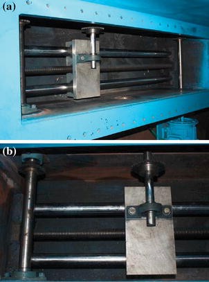
Real picture of mining system. a Rotational device of coal cutting shaft. b Stepping device of coal cutting shaft

The 32-channel data acquisition system is composed of four 8-channel data acquisition boards, an 8-port hub, a 7.5 V direct current switching power supply, three kinds of sensors and a computer processing system. The sensors are used to collect stress data at different locations under simulated mining conditions, gas concentrations and temperatures. The gas concentration is evaluated by gas pressure. The auxiliary system includes a crusher, portal jib crane, air pump, vacuum pump, vacuum gauge, hydrogen precision pressure gauge, vortex flowmeter and pressure machine.
Characteristics of the experimental system are as follows:
-
(1)
Large-scale experimental coal corresponds with the geometric similarity theories (Yang 2005).
-
(2)
The cribriform ventilation device is developed to feed well-distributed gas into the coal sample, which agrees with the in situ gas source in coal seams.
-
(3)
The mining system is developed to simulate the excavation process to reveal gas adsorption and desorption performance under mining conditions.
-
(4)
The loading system was also developed. Four hydraulic pressure load holes exist, which provide loads to the experimental coal sample by grade or step.
-
(5)
Intelligence and centralization of the data monitoring and information collection. All data acquisition work over a series of experimental periods is undertaken by a computer able to conduct preliminary statistical analysis. The experimental system can be used to study the performance of gas movement under different gas adsorption equilibrium pressure, moisture content and mining conditions.
2.2 Experimental procedure
-
(1)
Preparing coal sample. Raw coal is crushed to a diameter of 0.2–0.5 mm before being mixed with water to a certain proportion. During the coal preparation, moisture determination of the crushed raw coal was achieved by determining the total moisture in the coal (GB/T 211—2007, 2007). The crushed coal was well mixed with a certain amount of water, which was calculated from the difference between the required moisture content in the coal and the moisture determination. Further moisture determination was conducted to ascertain whether the required coal moisture had been achieved. It is necessary to wet or dry coal during this period until the coal sample moisture meets the experimental requirements.
-
(2)
Coal charging and seal. Certain 70-mesh stainless steel wire meshes were placed under the cribriform ventilation device at the bottom of the experimental platform primary box. Coal granules cannot cross the steel wire meshes, so the cribriform ventilation device under the steel wire meshes would not be blocked by coal granules. With the steel wire meshes in place, a layer of stones (10 cm thick; 20, 10 and 5 mm diameter) was laid to enable even gas to charge. After the stone paving had been laid, several 70-mesh steel wire meshes were placed on the stone layer. The stable stone pad forms the structure of the gas-charging base. The prepared coal is placed into a primary box and tamped. Pressure, stress and temperature sensors were placed in the coal sample at different layers and locations. The top shell was set in place and sealed. Leak detection was conducted to ensure that the experimental box was airtight.
-
(3)
Gas charging. When leak detection had been completed, the remaining air in the experimental box was extracted by vacuum pump. Gas was then charged into the experimental box through the pressure reducing valve. The valve was not closed until the pressure sensor indicated a specified adsorption equilibrium pressure.
-
(4)
Cyclic gas charging. The valve was closed, the gas pressure in the experimental box was reduced to a stable value and the gas adsorption reached equilibrium because of gas adsorption. Gas was charged repeatedly until the gas pressure reached a specified adsorption equilibrium value.
-
(5)
Gas desorption. A vortex flowmeter was installed and gas desorption was performed with the data acquisition system working. The mining system was enabled to simulate the mining work.
3 Performance of gas desorption experiment while mining
3.1 Experimental schemes
The scheme used to determine the gas desorption performance is shown in Table 1. Methane (99.9 %) was substituted for coal gas.
3.2 Experimental and analytical results
The isothermal adsorption curve is used to research the gas adsorption and desorption characteristics in the coal sample. Based on prior research, the isothermal adsorption curve follows the Langmuir equation (Yu 1992; Tsang 1999; Minkoff et al. 2003).
where X is the gas adsorption per unit mass of coal at a certain temperature and equilibrium pressure P (m3/t), P is the gas adsorption equilibrium pressure (MPa), a is the adsorption constant that denotes the maximum gas adsorption quantity per unit mass of coal at a certain temperature and infinite gas pressure (m3/t) and b is the adsorption constant (MPa−1).
The gas adsorption quantity per unit mass of coal can be expressed as:
where X i is the gas adsorption quantity per unit mass of coal in the ith experiment (m3/kg), ∆Q i is the total gas adsorption quantity at adsorption equilibrium and G r is the mass of experimental coal (kg).
where Q ci is the standard gas volume charged into the experimental platform (m3); Q di is the quantity of remaining free gas (m3); P 1i and P 2i are the gas cylinder pressures before and after charging, respectively (MPa); Z 1i and Z 2i are the coefficients of compressibility at P 1i and P 2i respectively; V 0 is the volume of the high-pressure gas cylinder, n × 0.04, n = 1, 2, 3 (m3); V d is the total remaining volume in the experimental platform (1.6 m3); P i is the gas pressure at adsorption equilibrium (MPa); T is the average temperature during the experiment (T = 17 °C) and Z i is the coefficient of compressibility at pressure (P i ) and temperature (T) (Yu 1992).
The gas cylinder pressure before and after charging was recorded. The quantity of adsorbed and free gas in the experimental coal was determined from Eqs. (1)–(5). The results are given in Table 2.
After the gas adsorption in the experimental coal reached its ultimate value, the vortex flowmeter was installed and the gas valve was switched on. The pressure of the experimental box was established at atmospheric pressure within a minute. The desorption experiment was performed according to the two schemes mentioned above, and data were collected by the vortex flowmeter to upload to the data processing system. The relationship between the quantity of gas desorbed and the time was obtained as shown in Figs. 4 and 5.

Relationship between quantity of gas desorption and time under natural and mining conditions

Relationship between velocity of gas desorption and time under natural and mining conditions
By analyzing Figs. 4 and 5, characteristics of this experiment are presented as follows.
-
(1)
Under nature conditions, gas desorption increases with time in an approximately parabolic shape. The desorption velocity decreases gradually. After 2200 min, the quantity of gas adsorbed reaches a stable value of 1.0 m3, and the desorption velocity tends to zero.
-
(2)
Under mining conditions, the coal sample undergoes unloading and collapse, and the coal sample permeability increases significantly. Thus the velocity and quantity of desorption increases simultaneously. After 120 min, the coal sample under mining will aid desorption. The quantity of gas desorption continues increasing, but the gas desorption velocity declines. After 420 min, the quantity of gas desorption stabilizes at 1.1 m3, and the velocity of desorption is zero.
-
(3)
The velocity of gas desorption is significantly higher than that under natural conditions. The degree of gas desorption is also increased.
4 Application
According to the characteristics of the desorption experiment mentioned above, the degree and velocity of gas desorption in the coal sample increase significantly. This is the most important law for improving the effect of gas extraction.
4.1 Gas extraction in current coal seam
The buried depth of fully mechanized caving face 15101 in a coal mine in the Yangquan mining area is 344–337 m. The tend strike length and the inclination length of the working face are 500 and 121 m, respectively. The thickness of the coal seam is 4.5–5.3 m, and the average thickness is 4.9 m. The dip angle of the seam is 8°–12°, and some parts of the seam are as large as 20°. The gas content of the working face is 18.48 m3/t, the gas pressure is 1.25 MPa and the permeability coefficient of the coal seam is 0.175 m2/(MPa2·d). The coefficient of gas flow attenuation per 100 m of coal seam bore is 0.0417/d. To extract gas in the current coal seam, extraction boreholes are located perpendicularly to the tunnel, parallel to the coal seam and 1.5 m from the coal seam floor. Gas extraction boreholes have a 60 mm diameter and 90 m length, and the interval between the boreholes is 5 m.
The current coal seam gas extraction boreholes arrangement of working face 15101 is shown in Fig. 6 (Wu et al. 2010).

Diagram of current seam gas extraction boreholes arrangement of working face 15101
The characteristic gas extraction of the No. 7 current seam extraction borehole is shown in Fig. 7, and the statistics of gas extraction of the current coal seam extraction borehole are shown in Table 3. According to Fig. 7 and Table 3, the coal mass permeability and gas desorption velocity are increased significantly because of the lead abutment pressure, and the gas extraction velocity 20 m in front of the working face is increased 5.82 times that of the borehole in farther places. The coal mass gas pressure decreases from the inner coal seam to the working face because of the existence of gas extraction boreholes. Gas desorption and migration is therefore encouraged. The area influenced by mining, which exists in front of the working face, is a key area for gas extraction, especially in coal seams with low permeability.

Characteristics of gas extraction of current seam extraction borehole of working face 15101
4.2 Gas extraction in adjacent seams
The gas emission from adjacent seams in working face 15101 is 25.65 m3/min. External alternate tail roadways are arranged for gas drainage and boreholes are drilled through strata in the roadway for preventing adjacent seams gas emission accident. The elevation angle of the boreholes is 46.5°, and they are drilled towards the gob. The angle between the boreholes and the coal side is 60°. The interval and borehole depth are 15 and 58.3 m, respectively. The ends of the boreholes are located at the fractured zone over the caving zone. Adjacent seams gas extraction boreholes of working face 15101 are arranged as shown in Fig. 8.

Diagram of arrangement of adjacent seams gas extraction boreholes of working face 15101
The relationship between the quantity of gas extraction and the distance of the No. 5 adjacent seams extraction borehole is shown in Fig. 9. The statistics of gas extraction of the adjacent seams extraction borehole are shown in Table 4. The zone of improved gas extraction appears 25 m away from the working face, and the effect of gas extraction further away remains at a low level. The overlying strata would undergo alternate collapse and caving with an increase in surrounding strata stress. The degree of gas desorption increases. Consequently, the quantity of gas extraction increases significantly to 545.6 times the value under undisturbed conditions. The gas extraction borehole remains behind with the advance of the working face. Boreholes may be blocked because of the moving strata, and the quantity of gas extraction may decrease immediately. Therefore, effective measures should be taken to extract the adjacent seams gas. The area of influence of mining in the overlying strata and a reasonable arrangement of gas extraction boreholes parameters should be recognized.

Characteristics of gas extraction of adjacent seams extraction borehole of working face 15101
5 Conclusions
-
(1)
A new experimental system was developed to research characteristics of gas adsorption and desorption for mining large-scale coal samples, with a maximum experimental coal sample mass of 1200 kg. The experimental system could simulate panel-charging, which agrees with the gas source under natural conditions. Mining systems were also developed to simulate mining conditions. A system was established to achieve gradual stepwise loading.
-
(2)
The research was conducted using the experimental system to establish the gas desorption characteristics under mining. The statistics from a series of experiments indicate that the velocity and degree of gas desorption increased significantly compared with natural conditions. The coal seam permeability improved because the pressure relief and failure of the overlying strata were influenced by the mining.
-
(3)
Based on the characteristics of gas desorption with mining, the area influenced by mining was determined and a reasonable arrangement of the parameters of gas extraction boreholes could improve the effects of gas extraction, and realize the simultaneous extraction of coal and gas.
References
Bai JP, Zhang DK, Yang JQ, Zhang H (2014) Thermodynamic characteristics of adsorption-desorption of methane in coal seam 3 at Sihe Coal Mine. J China Coal Soc 39(9):1812–1819
Barrer RM (1951) Difussion in and through solid. Cambridge University Press, Cambridge
Chen XG, Cheng YP, Wang L (2013) Experimental study on the inhibition of injection water to the gas desorption of coal. J Min Saf Eng 30(2):296–301
GB/T 211—2007 (2007) The determination methods of total moisture in coal
He XQ, Zhang L (2000) Study on influence and mechanism of gas ad-sorption and desorption in electromagnetic fields exerted. J China Coal Soc 25(6):614–618
He MC, Wang CG, Li DJ, Liu J, Zhang XH (2010) Desorption characteristics of adsorbed gas in coal samples under coupling temperature and uniaxial compression. Chin J Rock Mech Eng 29(5):865–872
Jiang YD, Xian XF, Yi J, Liu ZF, Guo CY (2008) Experimental and mechanical on the features of ultrasonic vibration stimulating the desorption of methane in coal. J China Coal Soc 33(6):675–680
Jiang YD, Xiong L, Yang XY, Xian XF (2010) Mechanism research on sound field promoting the coal bed methane desorption. J China Coal Soc 35(10):1649–1653
Li H (2011) Experiment research on the influence of ambient temperature on gas desorption laws of particle coal. Master’s Thesis, Henan Polytechnic University
Li SG, Zhao Y, Zhang TJ (2010) Test systems of the coal sample adsorption/desorption characteristics based on low-frequency vibration. J China Coal Soc 35(7):1142–1146
Lü XF, Pan YS, Liu JJ, Tang JP, Di JZ (2010) Experimental study of effect of pore pressure on desorption deformation of coal matrix. Rock Soil Mech 31(11):3447–3451
Miao XX, Liu WQ, Chen ZQ (2004) Seepage theory of mining rock mass. Science Press, Beijing
Minkoff S, Stone C, Bryant S, Peszynska M, Wheeler M (2003) Coupled fluid flow and geomechanical deformation modeling. J Pet Sci Eng 38:37–56
Tang JP, Pan YS, Li CQ, Shi Q, Dong ZX (2006) Experimental study in effect of effective stress on desorption and seepage of coalbed methane. Chin J Rock Mech Eng 25(8):1563–1568
Tsang CF (1999) Linking thermal, hydrological, and mechanical processes in fractured rocks. Annu Rev Earth Planet Sci 27:359–384
Wang ZF (2001) Gas desorption laws and application of coal in air, water and mud medium. Doctor’s Thesis, China University of Mining and Technology
Wang JC, Fan ZZ (2008) Key issues of coal and gas co-mining in thick seam. Coal Sci Technol 36(2):1–5
Wang ZF, Li XH, Qi LL, Sun R, Liu XQ (2010) The study of the moisture effect on gas desorption speed of Yangquan anthracite. Saf Coal Mines 7:1–3
Wu RL (2013) Effects of key stratum on the scope of the “three zones” of gas pressure relief and migration in coal seam group mining. J China Coal Soc 38(6):924–929
Wu RL, Xu JL, Qin W, Wang ZW, Zhang HP, Tian LX (2010) Experiment on advance pressure relief gas extraction in coal seams being mined in Xindadi coal mine. China Coal 36(4):83–85
Yang JJ (2005) Similarity theory and the structural model test. Wuhan University of Technology Press, Wuhan
Ye J, Shi BS, Zhang CC (1999) Coal reservoir permeability and its controlled factors in China. J China Coal Soc 24(2):118–122
Yu QX (1992) Methane prevention in coal mine. China University of Mining and Technology Press, Xuzhou
Zhang P (2012) Experimental and theoretical studies on longwall mining impact to the gas movement in solid coal. Doctor’s Thesis, China University of Mining & Technology (Beijing), Beijing
Acknowledgments
This work is supported by the National Key Basic Research Program of China (2013CB227903) and the National Natural Science Foundation of China (U1361209).
Author information
Authors and Affiliations
Corresponding author
Rights and permissions
Open Access This article is distributed under the terms of the Creative Commons Attribution 4.0 International License (http://creativecommons.org/licenses/by/4.0/), which permits unrestricted use, distribution, and reproduction in any medium, provided you give appropriate credit to the original author(s) and the source, provide a link to the Creative Commons license, and indicate if changes were made.
About this article

Cite this article
Wang, J., Wu, R. & Zhang, P. Characteristics and applications of gas desorption with excavation disturbances in coal mining. Int J Coal Sci Technol 2, 30–37 (2015). https://doi.org/10.1007/s40789-015-0060-7
Received:
Revised:
Accepted:
Published:
Issue Date:
DOI: https://doi.org/10.1007/s40789-015-0060-7