
Abstract
Microgrid (MG) is generally developed at utility terminal which contains lots of unbalanced loads and distributed generations (DGs). The interaction between MG and the unbalance loads or DGs will degrades the control performance of interfaced inverter in MG and dramatically leads to MG voltage unbalance. In this paper, a negative-sequence compensation based three-phase voltage unified correction strategy is proposed. While MG operates in islanded mode, a positive virtual impedance control is used to eliminate the negative voltage resulted from the negative-sequence current, and then a positive-sequence voltage control loop and negative-sequence control loop are used to improve the inverter control performance. While MG operates in grid-tied mode, the inverter operates as a negative-sequence current source to compensate the negative-sequence currents of loads to guarantee the point of common coupling (PCC) voltage balance. By using the proposed strategy, the voltage control performance of inverter can be improved; the MG power quality can be enhanced significantly. Simulation and experimental results verify the effectiveness of the proposed method.
1 Introduction
MG is a network which consists of distributed generations (DGs), loads, energy storage system (ESS), etc. The renewable energy such as solar energy and wind power is prior to be consumed by local loads in MG, which improves the utilization of renewable energy and minimizes the negative influence, resulted from the power fluctuation of renewable energy. Recently, microgrid has absorbed more and more attention [1–4].
MG can operate both in grid-tied mode and islanded mode. While it operates in islanded mode, the unbalanced voltage is mainly resulted from the unbalanced DGs or loads [5–7]. While MG operates in grid-tied mode, the unbalanced voltage is mainly resulted from unbalanced loads or utility failure [8–10]. Under the unbalanced condition, the inverter in MG output three unbalance currents, which contain a large percentage of negative sequence currents. The inverter performance would be seriously affected, the potential issues like: unbalance output voltage due to the negative voltage drop across the output impedance and the inverter output power is fluctuant, leading to voltage and frequency fluctuations [11]. The aforementioned issues degrade MG quality dramatically. The power quality standards ‘GB 15543—2008 Power quality three-phase unbalanced’ is proposed in China, which provides the regulations of voltage unbalanced factor (VUF) in different unbalanced conditions [12].
The voltage of islanded MG is depended on the voltage controlled inverters (VCI). Therefore, while islanded microgrid operates in unbalanced condition, most of the previous studies focus on the control system of inverter. Several control strategies base on the separation control of positive-sequence component and negative-sequence component, in which, firstly, the voltages and currents of inverter are decomposed into positive-sequence components and negative-sequence components, and then the positive control loop and negative control loop are developed to control the positive-sequence and negative-sequence components, respectively [6–10]. In order to enhance the performance of inverter controller, several new control schemes are proposed in existing studies, such as Lyapunov controller [13], negative impedance controller [14], secondary controller [15], repetitive controller and predictive controller [16, 17]. Using the aforementioned control strategy, the inverter positive-sequence voltage can be maintained and the negative-sequence voltage of inverter can be suppressed, the MG power quality can be improved.
In several studies, while the unbalanced voltage is resulted from the utility failure, a series converter is implemented between MG and utility grid to compensate the negative-sequence components of utility voltage and guarantee MG voltage balance [9].
Most of previous works focus on the individual inverter control. However, there are parallel inverters existing in microgrid. Generally, droop control and virtual impedance control are developed in control system to realize the power sharing during different parallel inverters. Moreover, the operating mode of microgrid should be switch according different utility voltage. Consequently, the aforementioned issues should be considered in the control strategy of MG.
After the analysis of the control system in parallel inverters and the operating mode of MG, a unified three-phase voltage correction strategy (UTVCS) based on negative-sequence compensation is proposed in this paper. This strategy is applied in the ESS inverter. It comprises a voltage compensation loop to suppress the voltage deviation due to the droop control, a positive-sequence virtual impedance to eliminate the negative-sequence voltage drop on the output impedance due to the negative-sequence current, and the positive and negative independent control loops to improve the inverter voltage control performance. While MG operates in grid-tied mode, the ESS inverter operates in negative-sequence current control mode to compensate the negative current of loads and to guarantee voltage balance. If the unbalanced voltage is resulted from the utility failure, MG switches its operation mode to islanded mode. In this case, the MG voltage depends on the output voltage of ESS inverter. Therefore, the MG voltage is still balanced in three-phase system.
2 Structure of MG and analysis of three-phase unbalanced voltage
The structure of MG is shown in Fig. 1. In this system, a transformer and a point of common coupling (PCC) switch between the utility grid and MG are used to isolate these two networks. The DGs and loads are connected into the AC bus of MG by power electronic converters.

Structure of MG
In Fig. 1, while PCC switch is closed, MG operates in grid-tied mode. In this case, the MG voltage depends on the utility grid. Therefore, the unbalanced voltage is resulted from two issues.
-
1)
Utility grid failure. Both single-phase short-circuit and double-phase short-circuit can result in three-phase voltage unbalanced. And then, the MG voltage transfers to unbalance.
-
2)
Unbalanced loads or single-phase DGs are connected into MG. In this case, three-phase unbalanced currents i PCC flow into MG. There is a negative-sequence voltage drop across the line impedance Z line, the PCC voltage can be expressed as
$$ \left[ \begin{aligned} u_{\text{PCCa}} \hfill \\ u_{\text{PCCb}} \hfill \\ u_{\text{PCCc}} \hfill \\ \end{aligned} \right] = \left[ \begin{aligned} u_{\text{ga}} \hfill \\ u_{\text{gb}} \hfill \\ u_{\text{gc}} \hfill \\ \end{aligned} \right] - Z_{\text{line}} \left[ \begin{aligned} i_{\text{PCCa1}} \hfill \\ i_{\text{PCCb1}} \hfill \\ i_{\text{PCCc1}} \hfill \\ \end{aligned} \right] - Z_{\text{line}} \left[ \begin{aligned} i_{\text{PCCa2}} \hfill \\ i_{\text{PCCb2}} \hfill \\ i_{\text{PCCc2}} \hfill \\ \end{aligned} \right] $$(1)where u PCCa,b,c are the PCC voltage; u ga,b,c are the utility voltage; i PCCa1,b1,c1 are the PCC positive-sequence current; i PCCa2,b2,c2 are the PCC negative-sequence currents.
As seen from the equation, there is a negative-sequence voltage in PCC, the MG voltage transfers to unbalance.
While MG operates in islanded mode, the MG voltage depends on voltage controlled inverters, such as the ESS inverter. While there is a large percentage of unbalance loads or single-phase DGs are connected into islanded MG, the voltage controlled inverter should supply enough negative currents to loads. Then there are negative-sequence voltage drop across the output impedance of inverter due to the output negative-sequence currents, which can be expressed as
where u oa,b,c are the output voltage of inverter; i oa1,b1,c1 are the positive-sequence output current; i oa2,b2,c2 are the negative-sequence output current; Z o is the output impedance of inverter; u ia,b,c are the voltage of inverter insulated gate bipolar transistor (IGBT).
It can be seen that the inverter output voltage will be unbalance while it outputs negative current to loads, then MG voltage will be unbalance. The three-phase balanced loads also consume unbalanced currents. Therefore the voltage controlled inverters need to supply more negative currents, which increase the VUF of MG.
3 Proposed UTVCS for MG
Under unbalanced voltage condition, the normal operation of power device would be impacted seriously. To overcome the aforementioned issues, an UTVCS based on negative-sequence compensation is proposed.
3.1 Proposed control strategy for Islanded MG in unbalanced condition
For islanded MG, in order to suppress the unbalanced voltage due to unbalanced loads or single-phase DGs, the corresponding voltage compensation strategy is introduced here. The control scheme is shown in Fig. 2, which is composed by time-domain transform algorithm (TTA) module [18], voltage deviation suppression module, and positive-sequence and negative-sequence control loops.

Proposed strategy for islanded MG in unbalanced condition
This control strategy is applied in ESS inverter. In the control system, TTA module is used to decompose the positive-sequence components and negative-sequence components of the feedback voltage and current [18].
where u cabc are the capacitive voltage of inverter; u cabc1 and u cabc2 are the positive-sequence and negative-sequence components of capacitive voltages; i Lfabc are the inductance current; i Lfabc1 and i Lfabc2 are the positive-sequence and negative-sequence components of inductance current; i oabc are the output current of inverter; i oabc1 and i oabc2 are the positive-sequence and negative-sequence components of output current.
Voltage deviation suppression module is added on the traditional droop control, which is used to compensate the voltage deviation, such as amplitude and frequency deviations due to the droop control [18]. In this case, the droop control is modified as
where U d and ω* are the voltage and frequency references; U n and ω n are the rated voltage and rated frequency; m and n are the droop coefficients; p and q are the active power and reactive power; u d and ω are the feedback voltage and frequency; k up, T ui, k fp and T fi are the PI parameters of compensation controllers of voltage amplitude and frequency, respectively; S is a logic judgment signal, which is generated by ‘if action’ module. While there is the power fluctuation in MG, the power sharing between different inverters does not finish, S is set as 0, to avoid the adverse impact on power sharing due to the voltage deviation suppression. While the power sharing has finished, S is set as 1, the voltage compensation variables are added in droop control to restore the inverter voltage.
In order to suppress the negative-sequence voltage cased by negative-sequence current, the positive-sequence current is used to realize virtual impedance control, as shown in Fig. 3.

Control scheme of positive-sequence virtual impedance
After the positive-sequence virtual impedance, the voltage reference can be expressed as
where U *d and U *q are the modified voltage references; i d1 and i q1 are the positive-sequence current; R vir and L vir are the virtual resistance and inductance; ω 0 is the fundamental angular frequency.
At last, a negative-sequence voltage control loop is used to eliminate the negative-sequence voltage and a positive-sequence voltage control loop to maintain the output voltage of inverter, as shown in Fig. 2.
By using the proposed control strategy, the voltage of islanded MG can be maintained to be three-phase balanced; the power quality of MG can be improved.
3.2 Proposed control strategy for grid-tied MG in unbalanced condition
While MG operates in grid-tied mode, both utility grid failure and unbalanced load would result in three-phase unbalanced voltage.
In China power quality standards ‘GB 15543—2008’, if the unbalance voltage is resulted from the power grid, the VUF should be less than 2%; if the unbalanced voltage is result from the loads, the VUF should be less than 1.5%. VUF is defined as
where X 1 and X 2 are the positive-sequence and negative-sequence components of electronic variable X.
To overcome the aforementioned issues, for a grid-tied MG, the proposed strategy is shown as follows.
-
1)
If the unbalance voltage is resulted from the power grid, the control strategy is shown in Fig. 4. It can be seen that, if the VUF is less than 2%, PCC switch is still closed, MG and the inverter of ESS keep their original operation modes. Otherwise, if VUF surpasses the national standard, MG switches to islanded mode. In this case, the inverter of ESS is working as voltage controlled mode to maintain the voltage of MG three-phase balanced.
Fig. 4 
Control flow chart end for grid-tied MG when unbalanced voltage is resulted from utility failure
-
2)
If the unbalanced voltage is resulted from the unbalanced loads or single-phase DGs, the control strategy is shown in Fig. 5.
Fig. 5 
Control flow chart for grid-tied MG when unbalanced voltage is resulted from unbalanced loads


It can be seen that, if the VUF is less than 1.5%, which is satisfy the national standard, MG and the ESS inverter keep their original operation modes. Otherwise, if VUF surpasses the national standard, the ESS inverter operates in negative-sequence current compensation mode. The control scheme is shown in Fig. 6.

Control scheme of ESS inverter in negative-sequence current compensation mode
It can be seen from the Fig. 6, when the voltage of MG is three-phase balanced, the current references of ESS inverter are generated by PQ controller.
where i *d and i *q are the current references; i dref and i qref are the instruction current calculated by PQ reference.
However, while the inverter operates in the mode of negative-sequence current compensation, the current of unbalanced loads i loaddq are feedback to control system, and then it is decomposed to positive-sequence components i loaddq1 and negative-sequence components i loaddq2 by TTA [18]. Then i loaddq2 are added into the original current references, to generate the final current references.
where i loadd2 and i loadq2 are the negative sequence currents of load.
Therefore, all the negative-sequence currents consumed by unbalanced loads are supplied by the ESS inverter. The negative-sequence voltage across the line impedance Z o due to the negative-sequence current can be eliminated. The voltage of MG can maintained as three-phase balanced.
By using the proposed strategy, the voltage of MG can keep three-phase voltages balanced under unbalanced condition, no matter in grid-tied mode nor islanded mode.
4 Simulation verification
A MG simulation model is implemented in PSIM, which contains a three-phase voltage source to simulate the utility grid and two voltage controlled inverters to simulate the ESS inverters. Detailed parameters are shown in Table 1.
Two tests are carried out to check the performance of the proposed strategy.
-
1)
Simulation for islanded MG in unbalanced condition.
Firstly, MG inverters are working with the traditional droop control, at 0.1 s, a set of three-phase balance loads are connected into MG, and at 0.2 s, a set of three-phase unbalanced loads are connected into MG. As shown in Fig. 7, after 0.2 s, the loads consume a large percentage of unbalanced current, in this case, the control performance of inverter is dramatically degraded, as shown in Fig. 8, after 0.2 s, the MG voltages u mabc become unbalanced.
Fig. 7 
Simulation curves of three-phase currents of inverter
Fig. 8 
Simulation curves of three-phase voltages of islanded MG with traditional droop control
The comparisons test is conducted, in which MG inverters are working with the proposed strategy.
Similar with the above section, Firstly, at 0.1 s, a set of three-phase balance loads are connected into MG, and then, at 0.2 s, a set of three-phase unbalanced loads are connected into MG. As shown in Fig. 9, after 0.2 s, the inverter performance keeps invariable, the MG voltages u mabc are still kept balanced in three-phase system. This test verifies the effective of the proposed strategy.
Fig. 9 
Simulation curves of three-phase voltages of islanded MG with proposed control strategy
-
2)
Simulation for grid-tied MG in unbalanced condition.
In this test, MG operates in grid-tied mode. As shown in Fig. 10, at 0.1 s, the MG voltages are three-phase unbalanced due to the grid fault. The VUF is 4%, which is larger than national power quality standard.
Fig. 10 
Simulation curves of three-phase voltages of grid-tied MG with utility failure
With the proposed control strategy, at 0.2 s, PCC switch is opened, MG operates in islanded mode, in this case, as shown in Fig. 11, MG inverters output three-phase voltages to MG. As shown in Fig. 10, the MG voltage is still balanced in three-phase system.
Fig. 11 
Simulation curves of three-phase voltages of ESS inverter


In next test, MG also operates in grid-tied mode. As shown in Fig. 12, at 0.1 s, there is a set of three-phase unbalanced loads are connected into MG. Then the MG voltages become unbalanced. At 0.2 s, the ESS inverters operate in negative-sequence compensation mode, namely all negative-sequence currents consumed by loads are supplied by inverters, as shown in Fig. 13.

Simulation curves of three-phase voltages of grid-tied MG with unbalanced loads

Simulation curves of three-phase compensation currents of ESS inverter
Consequently, the MG voltages shown in Fig. 12 are restored to balance in three-phase system.
5 Experimental verification
The effectiveness of the proposed strategy is verified in a MG laboratory prototype, which includes two ESS inverters, one PV system inverter, PCC switch, and loads. The two ESS inverters have same parameters, the capacity of which are 3 kW, filter inductance is 0.72 mH, filter capacitor is 60 μF. The capacity of PV inverter is 2.5 kW. The switch frequency of IGBT in inverter is 10 kHz.
Two experimental tests are carried out to check the performance of the proposed strategy.
-
1)
Islanded MG with unbalanced loads.
In the first scenario, the two ESS inverters are controlled by traditional droop control. At t 1, a set of unbalanced loads are connected into MG, as shown in Fig. 14, the MG voltages are three-phase unbalanced.
Fig. 14 
Experimental curves of three-phase voltages of islanded MG with traditional droop control
In the next text, the proposed strategy is applied into the ESS inverters. As shown in the Fig. 15, though a set of unbalanced loads are connected into MG at t 1, the voltages of MG are still maintained three-phase balanced.
Fig. 15 
Experimental curves of three-phase voltages of islanded MG with the proposed control
-
2)
Grid-tied MG operates in unbalanced condition.
In this scenario, MG operates in grid-tied mode. At t 1, the MG voltages are unbalanced due to the utility grid failure, as shown in Fig. 16. The VUF is about 7%, which is higher than national standard. In this case, MG switches to islanded mode at t 2, the voltage of which is maintained by the two ESS inverters. Consequently, the MG voltages are still three-phase balanced.
Fig. 16 
Experimental curves of three-phase voltages of grid-tied MG with utility failure
In the next text, MG is still operating in grid-tied mode. The two ESS inverters operate in traditional control strategy. At t 1, a set of unbalanced loads are connected into MG. All the negative-sequence currents consumed by the loads are from the utility grid. Then there are negative-sequence voltage drop across the line impedance. Consequently, the MG voltages become three-phase unbalanced, as shown in Fig. 17.
Fig. 17 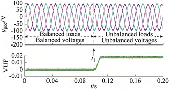
Experimental curves of three-phase voltages of grid-tied MG with traditional droop control


In contrast, when the proposed UTVCS is applied, the negative-sequence currents can be compensated by the ESS inverters. Then the voltage of MG can be restored to three-phase balanced, as shown in Fig. 18.

Experimental curves of three-phase voltages of grid-tied MG with the proposed strategy
6 Conclusions
The unbalanced loads or DGs connected in MG will interactive with ESS inverter, which would degrade the voltage control performance of inverter and leads to MG voltage unbalance. In this paper, a novel UTVCS based on negative-sequence compensation is proposed. In contrast to the conventional control strategy, with the proposed UTVCS, both the inverter control and the operation mode of MG are considered, hence the method in this paper has advantages in improving the MG power quality and it is simply realized. Simulation and experimental results shows the effectiveness of the proposed strategy.
References
He JW, Li YW, Guerrero JM et al (2013) An islanding microgrid power sharing approach using enhanced virtual impedance control scheme. IEEE Trans Power Electron 28(11):5272–5282
Majumder R (2013) Some aspects of stability in microgrids. IEEE Trans Power Syst 28(3):3243–3252
Carpinelli G, Mottola F, Proto D (2014) Optimal scheduling of a microgrid with demand response resources. IET Gener Transm Distrib 8(12):1891–1899
Gu YJ, Xiang X, Li WH et al (2014) Mode-adaptive decentralized control for renewable DC microgrid with enhanced reliability and flexibility. IEEE Trans Power Electron 29(9):5072–5080
Sun C, Ma WM, Lu JY (2006) Analysis of the unsymmetrical output voltage distortion mechanism of three-phase inverter and its correction. P CSEE 26(21):57–64 (in Chinese)
Deng WL, Yang XR, Zhu JL (2006) Study of closed loop control based on double synchronous rotating frame for two-stage matrix converter under unbalanced load. P CSEE 26(19):70–75 (in Chinese)
Peng L, Bai D, Kang Y et al (2004) Research of three-phase inverter with unbalanced load. P CSEE 24(5):174–178 (in Chinese)
Xu Y, Zheng JY, Mei J et al (2013) A novel control strategy for three-phase grid-connected inverter based on space phase analysis under unbalanced input voltage condition. Trans China Electrotech Soc 28(4):133–139 (in Chinese)
Li YW, Vilathgamuwa DM, Loh PC (2006) A grid-interfacing power quality compensator for three-phase three-wire microgrid application. IEEE Trans Power Electron 21(4):1021–1031
Wang F, Duarte JL, Hendrix MAM (2011) Grid-interfacing converter systems with enhanced voltage quality for microgrid application—Concept and implementation. IEEE Trans Power Electron 26(12):3501–3513
Shi HT, Zhuo F, Yi H et al (2015) A novel real-time voltage and frequency compensation strategy for photovoltaic-based microgrid. IEEE Trans Ind Electron 62(6):3545–3556
Lin HX (2006) National standards of power quality 5: Three-phase unbalanced. Popular Util Electr 6:39–42 (in Chinese)
Dasgupta S, Mohan SN, Sahoo SK et al (2013) Lyapunov function-based current controller to control active and reactive power flow from a renewable energy source to a generalized three-phase microgrid system. IEEE Trans Ind Electron 60(2):799–813
Hamzeh M, Karimi H, Mokhtari H (2012) A new control strategy for a multi-bus MV microgrid under unbalanced conditions. IEEE Trans Power Syst 27(4):2225–2232
Savaghebi M, Jalilian A, Vasquez JC et al (2012) Secondary control for voltage quality enhancement in microgrids. IEEE Trans Smart Grid 3(4):1893–1902
Delghavi MB, Yazdani A (2011) Islanded-mode control of electronically coupled distributed-resource units under unbalanced and nonlinear load conditions. IEEE Trans Power Deliv 26(2):661–673
Nian H, Yu NS, Zeng R (2013) Predictive current control for grid-connected inverter under unbalanced grid voltage. Power Syst Technol 37(5):1223–1229 (in Chinese)
Li HY, Zhuo F, Wang ZA et al (2005) A novel time-domain current-detection algorithm for shunt active power filters. IEEE Trans Power Syst 20(2):644–651
Acknowledgment
This work was supported by the project of China Electric Power Research Institute (No. GYB5120140 4488) and National High Technology Research and Development Program of China (863 Program) (No. 2015AA050606).
Author information
Authors and Affiliations
Corresponding author
Additional information
CrossCheck date: 28 November 2015
Rights and permissions
Open Access This article is distributed under the terms of the Creative Commons Attribution 4.0 International License (http://creativecommons.org/licenses/by/4.0/), which permits unrestricted use, distribution, and reproduction in any medium, provided you give appropriate credit to the original author(s) and the source, provide a link to the Creative Commons license, and indicate if changes were made.
About this article

Cite this article
SHI, H., ZHUO, F., YI, H. et al. Control strategy for microgrid under three-phase unbalance condition. J. Mod. Power Syst. Clean Energy 4, 94–102 (2016). https://doi.org/10.1007/s40565-015-0182-3
Received:
Accepted:
Published:
Issue Date:
DOI: https://doi.org/10.1007/s40565-015-0182-3