
Abstract
Through a critical review of recent literature on aluminum smelting cell energy balance, this paper defines specific energy constraints which govern the feasibility of cell operation in practice. Using these constraints as a basis, the objective of reducing energy consumption per kilogram of aluminum produced was examined, again with reference to published data and modern cell developments over the last 5 years. Both incremental and quantum steps in cell design are considered in this analysis, in pursuit of a pathway to lower energy consumption in a process where energy efficiency has not yet risen above 50 pct. In Section V and VI of this work, a generic high amperage cell technology is examined using a computational model of the cell energy balance, in which the resultant electrolyte phases and their thermal, electrical, and physical states can be determined. Using a series of trial energy balances, a feasible operating point emerges, and the possibility of flexible cell amperage and production rate is tested in a preliminary way. The specific energy consumption and market implications of this new technology direction are examined.
Recent Research in the Field of Smelting Cell Energy Balance
Understanding and improvement of the energy balance of aluminum smelting cells continue to be a limiting factor in both cell design and operation and in final performance. Modern, high amperage cell designs still suffer habitually from localized sidewall failures due to lack of understanding or control of the rate of thermal convection to the walls. Cathode deposits build up on modern cell cathodes causing horizontal currents and electromagnetic instability, increasing energy usage, and reducing efficiency.
Why this is the case now, after more than one hundred years of publications and excellent industry developments and training on this subject ? The answer can only be that the problem of achieving an acceptable energy balance is extremely difficult, especially in the context of the need to constantly increase production rate and reduce electrical energy consumption. The mind set of constantly increasing production is one which needs to be questioned in the context of international and local market signals, and this has been discussed in a recent market analysis.[1] This analysis concludes that structural oversupply and growing available stocks of aluminum will continue to drive lower prices despite healthy demand for the metal.
Recent studies of cell energy balance[2,3] have focused on building superior three dimensional hydrodynamic field models to predict heat transfer coefficients for the electrolyte and metal phases.[2] This excellent computational work has confirmed previous experimental studies[4] in terms of the magnitude of heat transfer coefficients from the electrolyte, but unfortunately, the resultant electrolyte conditions (temperature field and superheat) were not determined in these models—rather they were inputs to the simulation. The result is an unrealistic sidewall heat flux and ledge profile because the cell heat balance is not closed.
The impact of not achieving closure of the heat balance is also not recognized in the second major work on convective heat transfer coefficients in this decade, that of Solheim[3] in his seminal 2012 paper. Solheim’s comprehensive review of heat transfer measurements and predictions made over the past thirty years not only confirms the results obtained in the earlier experimental studies above,[3] but also re-emphasizes the importance of natural convection at higher electrolyte superheats.
However, Solheim’s assumption in this paper is that convective heat transfer is only a series resistance in the sidewall heat transfer calculation—rather than the driving mechanism and sole determinant for the heat flux. This assumption unfortunately leads to an erroneous heat balance due to much lower calculated heat fluxes based on the higher thermal resistances of the ledge and external shell/air resistance. This is the same heat transfer formulation problem which leads in practice to design failure of cell sidewalls through under-estimation of the sidewall heat flux from the electrolyte and metal phases.
Ledge composition and interfacial temperature have also been studied at length by Solheim[5] and separately by Yan et al.[6] at University of Queensland to better understand the impact of mass transfer limitations and compositional variation at the interface on possible sub-cooling of the “bath/ledge interface” below the liquidus temperature. This does occur in some viscous non-ferrous slags[6] (notably for copper smelting for example) but not for any length of time in aluminum smelting cells where the rate of mass and heat transfer at the ledge interface is far too high, as discussed earlier by Taylor et al.[3] and by Solheim.[4]
All of the above works have taken the understanding of the interfacial convection mechanism forward in their own right. What is still needed is a better appreciation for how the heat transfer from the electrolyte impacts the cell energy balance, given the urgent need to reduce energy consumption in a substantive way.
In other recent energy balance studies, the minor process and reaction energy contributions to this balance[7] were studied to determine if these alter the overall energy efficiency of the process. These reaction energy requirements include bath and anode cover melting, excess carbon, and anode assembly heating and also back reaction of aluminum in the cell. Altogether, an additional energy requirement of approximately 0.3 kWh/kg AL. could be attributed to these minor energetic requirements. However, many of these contributions had been included by Chen et al.[8] in their much earlier discussion of Knacke’s original formulation of the theoretical energy requirements[9] using a direct balance of the temperature-dependent enthalpies for the system.
These more recent academic contributions have advanced the detailed knowledge of the process energy requirements. However, they have not altered or addressed the fundamental issue in aluminum smelting which is that 50 pct of the energy input is wasted as heat. The process energy requirements which have been computed by the above investigators range from a minimum or theoretical requirement of 6.34 DC kWh/kg for a 100-pct efficient electrochemical reaction and with the stoichiometric materials inputs, to a somewhat higher requirement of 7.05 DC kWh/kg for a set of real conditions defined in References 8 and 9 above including a current efficiency of 89.5 pct and a gross carbon usage of 500 g/kg AL.
In recent TMS Meetings, the shell heat exchanger technology of Light Metals Research Centre in Auckland has been presented[10,11] in 2009 and 2011, respectively. This technology was originally aimed at extracting more heat from the sidewalls of high amperage cells but in the last 3 years has been developed further for the purpose of reducing sidewall and cell heat loss under conditions of reduced amperage. This development will be discussed further in the context of a related technology for reducing draught and top heat through specific extraction points for cell fume around the point feeding holes.[12]
Energy Balance Constraints
The loss of 50 pct of the energy input to smelting cells as heat is an outcome of a complex process. Several process constraints have ensured that specific energy consumption continues to be approximately 100 pct higher than the technical limit for the process of 6.5 to 7 DC kWh/kg discussed above. These constraints are enumerated below in a quantitative manner based on the authors’ observations of many modern cell technologies over the past decade.
-
1.
Frozen cryolite protection of the sidewalls this is essential to prevent their rapid corrosion due to wetting and intercalation of carbon materials and/or silicon carbide bricks by sodium and its salts. Solidification of ledge on the walls requires a heat extraction of 9 to 14 kW/m2 from the shell of the sidewall, in order to match the convection from the superheated electrolyte. Sidewalls must therefore be thin and conductive, and the steel shells must operate at 623 K to 773 K (350 °C to 500 °C) maximum temperature so that these large heat fluxes can be convected and radiated into the air around the cells. Thirty to forty percent of the total heat loss is extracted from the cell walls. Failure or severe damage to sidewalls is still widespread within the industry because of the high localized heat fluxes at certain regions on the sidewall, as shown in the infra-red camera photographs in Figure 1 for a 360-kA cell and an older 200 kA cell technology. The hot spots identified on the shell are above 723 K (450 °C) in both cases. If more insulation is applied to modern cell walls without corresponding reduction in the incident heat flux from the electrolyte and metal, the ledge is quickly melted, and sidewall corrosion and failure can follow within one working day.
Fig. 1 
Thermal images of the sidewall of a 360-kA cell (a) and a 200-kA cell (b) showing localized zones of high heat flux, with maximum detected temperatures of 735.7 K and 698.8 K (462.7 °C and 525.8 °C), respectively
-
2.
The top of the cell must be covered by a mixture of alumina and crushed bath, in order to prevent uncontrolled fugitive heat losses and fluoride emissions and to protect the carbon anodes which operate at above 873 K (600 °C) and will burn quickly in air. This ‘crushed bath blended cover’ material[13] is superior to the original alumina cover material used up until the 1970s but still suffers from thermochemical instability of the resulting sintered top crust due to:
-
a.
Poor thermal conductivity due to excessive fines content in the applied granular cover giving high porosity and rapid heat build up in its interior after it is applied to a new anode. This leads to temperatures in excess of 1073 K (800 °C) inside the crust as it is sintered and results in heat fluxes for modern cells with 0.5 to 0.6 m cavity depth and 15 to 20 cm total cover depth of 1.6 to 2.0 kW/m2.
-
b.
Low temperature, solid to liquid phase transitions due to the increased chiolite content of the heat treated crust. These phase transitions are mainly incongruent melting of chiolitic phases to produce eutectic liquid and cryolite and occur in the temperature range 953 K to 993 K (680 °C to 720 °C),[14] resulting in a high liquid phase proportion in the crust where temperatures exceed 973 K (700 °C).
-
c.
Constraint b above leads to two main issues with respect to the top heat loss from cells. Firstly, holes can form in the top crust because of its thermochemical and therefore thermomechanical instability, especially on anodes which are further into their life cycle and where the anode cover submerges the anode pins. Holes in the crust release both fugitive fume and excessive heat continuously unless they are quickly repaired by manual operations. The second issue is similar to that encountered with the cell walls—extra cover thickness applied to the top of anodes to reduce heat flux through the cover causes even higher temperatures within this material. These temperatures exceed 1073 K (800 °C) and increase liquid phase content. Weakening and melting of the crust occur,[14] causing very high heat losses and defeating the purpose of the extra cover thickness—as shown in Figure 2 for several cell technologies.
Fig. 2 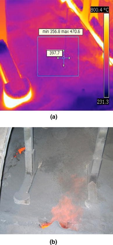
Thermal image (a) and normal photograph (b) of the same cell at different times with a high level of anode cover applied—extending up to almost the full height of the anode pins. In (b), the anode cover is partially collapsing due to its temperature
-
a.


Together, these crust mechanisms have resisted attempts to reduce top heat loss from cells. Between 47 and 55 pct of heat loss escapes from the top of modern cells, by convection and conduction through the crust or out of the anode pins electrical conductors at a rate up to 1 kW per pin. Larger anode pins can reduce anode top temperature giving better electrolysis and less anode oxidation, and coarser anode cover material gives denser packing and better thermal conductivity.[13] However, the above improvements have not changed the fundamental thermochemical instability of the anode cover material or allowed better overall insulation of the top of most modern cell technologies. In this respect, the control of anode top temperature on mature anodes below the liquification temperature range of the cover is one good indicator of the stability of the crust material and the top heat loss. Melting of the anode cover on top of the carbon anode is a common observation in modern, high amperage cells, as shown in Figure 3 for another 350 kA cell technology.

Crust completely melted from the top of two anodes due to anode surface temperatures in excess of 1073 K (800 °C)
Evidently, approximately 85 pct of the heat loss from cells is presently controlled by the two constraints described above—this is confirmed for a typical technology in Section V of this paper. Heat extraction at the present heat fluxes is required from both cell walls and from the top of the cell in order to stabilize the operation of these cell components for containment of the bath, metal, and fume within the cell and in fact for continuity of the cell operation itself.
Efforts to Reduce Heat Loss in Modern Cells
Despite the above fundamental difficulties, significant progress has been made in recent years in the industry to reduce the specific energy consumption which stood at a benchmark of 13.0 DC kWh/kg for many years,[15] with several smelters in that period achieving 12.7 to 12.9 DC kWh/kg. For example, the work of Alouette in collaboration with RTA and published in 2012[16] has produced results in the 12.6 to 12.7 DC kWh/kg range for their latest generation of modified AP35 technology, through reducing anode cathode distance and maintaining cathode instability at a low level using fine adjustments of the cathode temperature profile. This has been achieved while increasing cell amperage from 380 to 395 kA.
Chinese technologies have taken a vastly different path over the last 10 years, however, with anode current densities for new 400 and 500 kA technologies in the 0.75 to 0.83 A/cm2 range and very low bus bar current densities as well. Combined with effective electromagnetic designs, the technologies of SAMI and NEU have achieved as low as 12.8 DC kWh/kg in several smelters[17] and might achieve less than 12.5 DC kWh/kg if current efficiency could be raised above 90 to 91 pct. This current efficiency limitation is largely due to poor anode quality and lack of control of operations in China, though there are signs now that both of these process management limitations will be addressed in coming years.
Despite the progress described here, both Chinese and Western large cell technologies have not been able to reduce heat loss from the cell itself, however. Gains in specific energy consumption for Western technologies have been due to passing more current through the cell, thereby increasing production and reducing energy consumption per tonne of aluminum produced. This amperage raising strategy can result in gains in energy consumption, at least until one of the heat balance constraints above is met—usually with unintended consequences such as higher anode temperatures and anode consumption, along with lower cell lives and damage to the cell and potline conductors due to excessive temperatures. One study on the marginal value of increasing production through increasing amperage was conducted based on a smelter’s history of amperage increases and associated anode failures.[18] This study showed that at a particular point in the smelters’ history in 2002, increasing amperage actually reduced the profit margin for each tonne of metal produced because of the additional costs (waste) incurred, including anode failure, compressed air for sidewall cooling, anode rod repair costs, cell failures, unplanned cell reconstruction costs, and unplanned labor costs.
Inability to reduce cell heat loss has also placed an absolute limit on the extent of sustainable cell voltage reductions in the large, low current density Chinese technologies mentioned above. Although these cells are physically able to operate at lower anode cathode distance, they cannot sustain lower heat dissipations. In fact, the heat dissipation of most Chinese technologies is already at the low end of feasibility, giving very thick sidewall ledges and electrolyte superheat which regularly averages less than 5 K[19] from quoted electrolyte temperatures and cryolite ratios. The implications of low superheat for operating stability of these very large cells are not recognized by Chinese smelters[17,19–21] yet, though the resulting alumina feeding problems are endemic across these high amperage potlines. The lack of electrolyte superheat also exposes the cathodes to a very high risk of alumina sludging and hard cathode deposits developing over only 1 to 2 years of operation, giving rise to poor potline performance and low effective cell life due to the onset of chronic voltage instability. In the authors’ observations, this is an often repeated pattern in many modern Chinese potlines over the last 10 years.
Revolutionary cell designs have been under development for more than 20 years in an attempt to make a quantum step in cell heat loss. Chiefly, these designs aim to address the above constraints and the anode-cathode distance constraint through:
-
1.
Reducing or draining the metal level in the cell to less than 5 cm depth This technology family is commonly known as drained cathode cells (DCC) or in the case of the Chinese versions as new structured cathodes (NSC). Both of these technologies have historically been difficult to develop: DCC because of materials corrosion problems associated with a cathode wettable by aluminum and the NSC more recently because the anode changing and alumina feeding infrastructure of present technologies are not compatible with drained cathodes or very low metal depth. In respect of the latter issue, it is observed in China that anode cavity cleaning technology can destroy the raised NSC cathode surfaces, and that alumina deposits and crust pieces quickly ruin the carefully designed metal draining surfaces and channels for both DCC and NSC technologies. Anecdotal evidence from China have indicated for several years that the NSC cells installed at various smelters do not have improved performance compared with conventional, flat cathode cells. This was confirmed recently in the paper of Li et al.[21]. where “conventional planar cathodes but with proper heat preservation enhancing” were found to be superior in sustained potline testing compared with drained (NSC) cathodes and other bus bar and collector bar modifications.
The DCC technology of RTA may yet be applied to an AP60 variant at Jonquiere in the future, though the timetable for this is not yet clear.
-
2.
Inert Anode Technology where radically different electrolyte and cell design may remove the sidewall and top crust transfer constraints These technologies are still under development by several companies, of which the leaders appear to be Alcoa, with other majors such as Chalco and Rusal also developing interesting programmes in the past 5 years. My assessment is that inert anode technology is some years away from viability, and its success is by no means assured because it relies on a chain of materials and enabling technologies which need to be engineered and tested at full production scale, with significant capital risk. The technology has the potential to reduce energy consumption to less than 11 DC kWh/kg AL, but to do this it is certain that both the heat balance constraints will still need to be overcome.
The Energy Balance for Large Modern Cells
Given the fundamentals described above and the daily struggle for smelters to produce aluminum at lower cost with an inexorably increasing electricity price, the focus of this paper is on reducing cell heat dissipation and is limited to conventional, pre-baked anode cell technologies which today produce more than 94 pct of the world’s primary aluminum.
Control of the heat dissipation from the electrolyte to the sidewalls and to the top crust is driven by the mechanism of convection from within the electrolyte to these solid electrolyte interfaces. The convective heat flow is based on the differential in temperature between interface and the bulk liquid electrolyte where the surplus in heat generation (after the endothermic dissolution and electrolytic reduction of alumina to aluminum) actually occurs. The electrolyte energy balance is shown schematically in Figure 4 for one zone of the cell visualized as a continuous stirred tank reactor interlinked with other CSTR’s (zones) within the cell. This network of connected CSTR’s can describe both practically and numerically the energy balance, including the solidified ledge and crust interfaces to which the liquid’s surplus heat generation must be transferred. The diagram is adapted from Taylor et al.[22]

Continuous stirred tank representation of the dynamic enthalpy balance in one zone of the electrolyte of a smelting cell. The zones are interlinked by the channels formed between anodes and also the ACD of the cell. Symbols are defined below
From Figure 4, the enthalpy balance can be written simply as follows:
where V decomposition is the decomposition potential for the alumina electrolysis reaction, being the sum of the Nernst potentials for the anode and cathode half reactions, V IR is the Ohmic voltage drop in the electrolyte, η is the over-voltage at each of the anode and cathode due to activation polarization and concentration polarization, V ELECT is the sum of all of the above voltage components in the electrolyte, and V REACT is the voltage equivalent of the enthalpy required for the total chemical reaction, including alumina dissolution, back reaction of aluminum, heat up of anodes and steel assembly, and minor reactions. This enthalpy clearly is a dynamic quantity but can be averaged over time as in this steady-state representation of the balance, Surplus Q GEN is the left-hand side of Eq. [1], I is the Amperage in this zone of the cell, h(T e − T i ) is the local heat transfer coefficient, h, for interface i, multiplied by the temperature differential between the electrolyte T e and the solidified interface T i . T i is the interface temperature and, in the case of the sidewall ledge is normally the liquidus temperature of the bulk electrolyte. However, the temperature of primary crystallization (liquidus) varies throughout the cell depending on the composition of the electrolyte there—electrolyte nearer to the cathode surface (which is in communication with sludge on the cathode) is higher in both alumina content and cryolite content than the bulk electrolyte.
Local heat transfer coefficients, h, also vary widely throughout the cell, tending to a maximum at the three-phase bath/metal/ledge interface.[23]
The local heat transfer rates must therefore be integrated across the full (ledge, or crust) interface areas, A, as well as across the metal interface area. In this latter case, the controlling heat transfer resistance is actually the cathode insulation which is high in modern cells. This results in a liquid metal temperature only 1 K to 4 K[24] below the electrolyte except when thermal shocks occur such as undissolved alumina dropping into the metal as sludge.
The local heat transfer coefficients, h, are a combination of natural and forced convection in the case of the ledge, but there is an additional bath film resistance opposite the metal phase in the cell.[4] At the crust interface, radiation must be taken into account within the local heat transfer coefficient due to the electrolyte surface often being covered with carbon dust and being some centimetres away from the crust above.
In the heat dissipation to the crust, it is not certain that the crust interface temperature is the electrolyte liquidus point, though recent experimental evidence regarding the composition of the crystalline bottom face of industrial crust samples in modern point fed cells does support the hypothesis that the composition of this interface is close to cryolitic. Therefore, the interface temperature is near the liquidus point of the electrolyte at least for crusts in close proximity to the electrolyte.[25]
Examination of Eq. [1] indicates that the surplus heat generation (left-hand side of equation) should have a strong relationship with the differential in temperature between the electrolyte and the ledge and crust interfaces. It is at least clear that these solid/liquid interface temperatures do generally relate to the primary liquidus point of the bulk electrolyte, so the electrolyte superheat should be related to the surplus heat generation in the electrolyte. This relationship will be further explored through a more detailed model of the total cell heat balance in the next section of this paper.
Case Study on Energy Balance for a Low Current Density, 360 kA Cell
The evolution of larger cells in aluminum smelting has resulted in longer cells—up to 20-m long for 500 to 600 kA technologies, but of approximately the same width of 4.1 to 4.5 m. However, the complete table of anodes—up to 48 to 52 for these longer cells—are still connected in a low resistance parallel electrical circuit through an electrically continuous anode beam. There are still only 5 or 6 alumina point feeders in these cells, and the total alumina fed each day is now greater than the active electrolyte volume for its dissolution. If the added alumina is not dispersed, distributed, and dissolved equally between the anodes and particularly along the cell, some zones become quickly depleted in dissolved alumina, and large localized currents are forced into individual anodes in the higher alumina concentration zones, causing localized disturbances as discussed by Wong and Marks recently.[26]
These high anode current densities are sufficient to exceed the critical current density for alumina electrolysis on individual anodes, causing locally high potentials on one or more anodes in the cell. The large anode current differentials between anodes also give rise to horizontal currents near the surface of the liquid aluminum below the electrolyte (which is effectively an equipotential) and transient rotational forces then induce wave motions in the liquid aluminum. These metal pad disturbances may actually extinguish the localized anode effects in many cases. ‘Ghost anode effects’ and continuous perfluorocarbon emissions are observed in these ‘very long cell’ technologies.[26]
The performance especially of Chinese feeding systems in dispersing alumina equally to each anode is imperfect as exemplified by the data reported from Wong and Marks[26] and also observed in unpublished studies at other Chinese smelters. These problems are greatly exacerbated by low electrolyte superheat which causes feeder holes to close or become blocked, as well as affecting the dissolution of the alumina itself.
It is therefore crucial in the design of the cell energy balance for electrolyte superheat to be maintained above a certain level, in order to restrict the amount of cryolite solidification into the crust around feeder holes, onto newly set anodes, onto alumina as it is added to the cell and also into the sidewall ledge.
To illustrate the narrow window of variation in heat extraction possible in a modern cell technology, a number of computer simulations have been run using Eq. [1] above as a basis, within a three-dimensional finite element, steady-state thermo-electrical model framework developed by LMRC at the University of Auckland. This model differs from many others published earlier only in that it computes the full thermal field in the liquid phases as well as in the solid cell materials and in the use of experimentally determined convective and radiative heat transfer coefficients. Therefore, the resultant, steady-state superheat and ledging conditions in the cell cavity are obtained in this model, within the limits of accuracy of the experimental heat transfer coefficients.
Development and validation of the above model have taken place over five years using the two cell technology depicted in Figures 1 and 2. The critical validation points are
-
The top crust heat transmission and temperature field in the crust and anode assembly.
-
The sidewall heat transmission and temperature field, as well as the thickness of the sidewall ledge.
In the former case of computation of top heat loss and temperatures, a detailed validation has taken place on the cell in Figure 2, as detailed in a previous publication.[27] In the latter case concerning the sidewall heat loss, the moving ledge boundary inside the cell creates a large measurement uncertainty in terms of estimation of the steady-state heat transmission through the walls. A full scale experimental sidewall, with close control of the heat transfer coefficients on the external shell of the cell and the internal heat generation, was therefore implemented in the laboratory,[28] and the corresponding shell heat flows and temperatures were then compared with those generated by the developed model, using previously experimentally determined local heat transfer coefficients.[23]
The crucial aspect of the sidewall heat flow validation is correctness of the heat flux being transmitted through the sidewall in the model which in reality can exceed 15 kW/m2. These heat fluxes determine both the total heat transmission and also the shape and thickness of the solidified ledge on the sidewall. In the present model, a close prediction of this sidewall heat flux and therefore electrolyte superheat (from Eq. [1]) has been achieved, as indicated by the maximum temperatures exemplified in the specific industrial cell in Figure 1(a), and those predicted in Table I for Case 5, which correspond to the cell voltage and amperage for the cell in Figure 1(a).
The 360 kA cell technology is analyzed in detail here. This is a low current density 360 kA cell which shares characteristics of a number of low current density cells in China in the 400 kA range and has dimensions 17.5 m × 4.1 m.
Figures 5 and 6 show 2D thermal cross sections for two cases of this trial energy balance. Only half of the cell cross section is shown here because of symmetry around the central, feeding channel of the cell.

Thermal cross section for Case 1 in Table I

Thermal cross section for Case 5 in Table I
The predicted ledge profiles for Cases 1 and 5 shown differ greatly as do their heat balances which are described in Table I.
The first section of this table gives the independently specified variables in the simulation, which are the amperage, ACD, and the levels of the materials in the cell. A certain degree of pragmatism must be adopted here since the level of sludge is really an outcome of the whole cell operation and cannot be predicted from the thermal balance alone. This sludge level is varied in the simulations between the known, average conditions of cells operating in these smelters. For example in Case 1, the sludge level is set at zero to represent a new cell which has a clean cathode.
In the second section of Table I, the resultant, steady-state conditions for the cell energy balance in the five cases are presented. These conditions start with the total cell potential developed through the anode, cathode, electrolyte, and external bus bars, from which the surplus heat generation is derived as described in Eq. [1] above. Next, the total heat dissipation is computed by integrating heat losses around the cell boundaries in the model, and this is broken down in the table to show the individual heat losses from the sidewalls and top crust—observed to represent about 84 pct of the total heat dissipation in these cells. The differential in temperature, T e − T i , is the electrolyte superheat in these simulations since the interface temperature has been assumed to be the liquidus point for the ledge interface. No assumption is made about the crust interface temperature because of the compositional variation within the body of the crust.
The maximum sidewall shell temperature ranges widely but can be seen for Case 5 to be slightly above the measured values in Figure 1(a), for a particular 360 kA cell design. From the tabulated Ledge thickness and the thermal cross section for Case 5 (Figure 6), it is evident that this thermal condition represents a ‘No Ledge’ situation for the generalized 360kA cell, in which serious sidewall corrosion and cell failure would be expected to occur.
Conversely in Case 1, the ledge profile is very thick, but the electrolyte superheat is less than 5 K, indicating that the alumina feeding system is very unlikely to be able to maintain the clean cathode (zero sludge) situation which has been input into the simulation. In practice, it is also very difficult to maintain the liquid electrolyte level (input as 18 cm in these simulations) at a superheat of 5 K or less because of freezing during cell operations such as anode replacement and cavity cleaning.
Both Cases 1 and 5 are therefore inoperable from an energy balance point of view. These trial balances fail the ledge and electrolyte superheat constraints at opposite ends of the surplus heat generation scale. In addition to this failure, both cases also have anode top temperatures of approximately 1043 K (770 °C) which is 50 K higher than the maximum melting range of the chiolite phase in the crust. This means that the actual position of the crust at steady state will be similar to that shown earlier in Figure 3—leaving a large air gap above the anodes as they mature past their half life. Breaching of the crust temperature constraint has occurred because of the high anode cover used in these cases—covering the anode pins almost entirely in a similar way to those in Figure 2.
As indicated in Figure 2 also, the top heat dissipation is unstable, with holes in the thinning crust likely to develop over time, and air gaps above anodes reducing the thermal insulation provided by the applied anode cover. An increase in top heat loss is the inevitable result of this thermochemical instability, invalidating the thermal insulation values of the applied anode cover in the simulations.
Comparison with Case 2 shows that a significantly lower anode top temperature of 993 K (720 °C) is achieved if the height of the anode cover is reduced to a level where the anode pins are exposed to cross-flow convection from the air draught above the cell. This reduced temperature stabilizes the crust above the anodes as well as the heat loss from the top of the cell. The cost of this more stable crust is a higher heat extraction: 30 to 40 kW higher than Cases 1 or 2. The extra heat extraction causes Case 2 to have almost the same superheat as Case 1, despite the higher Surplus Heat Generation in Case 2. Most of the extra heat is extracted through the top of the cell, leading effectively to no net increase in electrolyte enthalpy and temperature above the liquidus point.
Also, in Case 2, a more realistic sludge level (4 cm) is applied to the cathode on the basis of the low computed superheat. The ledge profile changes dramatically due to the cooling of the cathode, and ‘ledge toe’ extends some distance across the cathode and under the anode, shown in Figure 7 where the ledge profiles for the five cases are compared.

Ledge profiles for thermo-electric simulations: Cases 1 to 5
Some ledge toe coverage of the cathode ends is necessary from the viewpoint of preventing metal leakage into the sub-cathode and also from a magneto-hydrodynamic point of view since it reduces the tendency for electrical current to ‘short circuit’ through the metal toward the ends of the cathode blocks. However, horizontal currents back into the center of the cell may also be generated in the metal layer if the ledge toe extends too far. This too has been computed by the present model but is not examined at this point in the trial energy balance design. In fact, Case 2 is still very marginal in terms of electrolyte superheat operability, with a high risk of deterioration in cathode condition (hard alumina sludge deposits) over 1 year of operation. This assessment is experiential, based on previous observations of different technologies of this type at low measured electrolyte superheats over a number of years.
Thus, from Table I and Figure 7, the only possibly operable cases are 3 and 4. Both have superheats in a feasible range [7.6 K and 10 K] and feasible ledge profiles, though Case 4 minimum ledge thickness is low—1.3 cm. However, again, experiences by many smelting companies have shown that this thin ledge coverage is sufficient to prevent rapid sidewall corrosion. Two additional factors must be considered in Cases 3 and 4, however:
-
Both cases have high anode cover—over the anode pins. Extra heat extraction is required here, of the order of 35 kW through a thinner anode cover, to stabilize the top of the cell.
-
Case 4 has achieved its higher superheat partly through reducing metal height to only 10 cm—perhaps through the implementation of one of the new structure cathodes (NSC) discussed earlier. Achieving such a low metal height is an hypothesis in itself and not without substantial risk. In fact, a reduction in metal level to 15 cm is more realistic and still a stretch for most smelters, because of the need for more precise control of cathode condition so that newly set anodes do not contact accumulations of alumina sludge or crust pieces on the cathode.
From the above considerations, it is evident that neither Cases 3 nor 4 can be considered to be operable without further investigation. In fact, an operating point may lie between the two cases—both an intermediate metal height and a cell amperage in the range 360 to 390 kA. Combined with a lower, stabilizing anode cover height, this should provide an operable energy balance—with sufficient heat extraction from the sidewalls and top of the cell and adequate electrolyte superheat for alumina feeding and clean cathode operation.
An operable energy balance window is a necessary but not a sufficient condition, of course for good cell performance. The control of alumina feeding, cell operations such as anode replacement, and responses to abnormal events contribute strongly to the performance outcomes which can be attained. An operable energy balance design is the foundation for this performance.
From the present analysis, it is evident that despite having a current density of only 0.75 A/cm2, the generalized 360 kA cell has a narrow operable energy balance range and if not adjusted to a viable balance point will perform poorly in a number of ways:
-
Low superheats and poor alumina feeding behaviors such as blocked feeder holes, uneven anode currents, and localized anode effects, as described earlier in Section V.
-
Sidewall ledge control difficulties due to thick ledges which extend onto the cathode but can become too thin on the lower sidewall if heat generation increases in the cell—for example, during metal pad instabilities.
This analysis is a simple demonstration of why energy balance constraints need to be the first consideration in cell design and operating parameter optimization, since both electromagnetic and alumina feeding performances depend implicitly on a viable energy balance which does not breach the criteria set out in Section II of this paper.
The Case for Flexibility in the Energy Balance
The modeling study in Section V is generally applicable to other smelting technologies because the energy balance constraints are generic; all smelters are trapped in one way or another between these constraints, and the need to reduce energy input per tonne of metal produced. Ultimately, a certain, high level of energy extraction is necessary to match the heat transfer from the electrolyte to the ledge, and the crust or these barriers will be breached or become too thick to allow cell operations like alumina feeding. This condemns smelting cells to high wastage of energy as heat.
An alternative approach is needed in order to control the heat extraction in concert with the heat transfer from the electrolyte and to utilize the vast electrode cross-sectional area of modern cells in a more energy efficient way. The sidewall heat exchanger technology of LMRC[11] in combination with a designed feeder hole fume extraction system[12] to lower total cell draught may be one solution to this problem. Both of these technologies have been conceived to give a controlled reduction in the heat extraction from the cell.
However, this is only half of the solution. As heat extraction is reduced, heat dissipation from the electrolyte also needs to be reduced in proportion to the lower cell heat extraction. Without massive alterations to the internal cell resistance and electrochemical over-voltages, the only way to achieve this is to reduce amperage on the potline. The advantage of doing this is that all of the ohmic voltage drops will be reduced in proportion to the amperage reduction. For example, in the case of the 360 kA cell modelled in Section V, a 100-kA reduction in amperage for Case 4 gives an amperage of 290 kA and a cell voltage of 3.38 V at the same anode cathode distance of 3.54 cm, simply through ohmic voltage reduction. The anode current density is now only 0.60 A/cm2, compared with 0.81 A/cm2 in Case 4.
To sustain this reduction in voltage, the total heat dissipation will need to reduce from 684 kW for Case 4 to 410 kW for the new 290 kA operating point. Given that 90 pct of this reduction must come from the sidewalls and top of the cell, it is evident from Table I that a 44-pct reduction in heat extraction must occur from both locations. This appears to be feasible at least on a laboratory scale through close control of the convective heat transfer from the sidewalls inside their heat exchanger envelop,[11] but achieving the same saving in heat loss from the anode rods and crust above the cell has not yet been physically tested. It does appear to be feasible theoretically.[12]
If this degree of heat loss reduction could be sustained in the present case, cell energy consumption would be reduced to approximately 11 DC kWh/kg or less if current efficiency was maintained above 91 pct. Aluminum production rate would be reduced by 25 pct but could be increased again rapidly on a potline basis if the combination of metal price and electricity price warranted it. In fact, this scenario encapsulates the economic issue for today’s aluminum smelters:
Is flexibility of aluminum production possible, through rapid and controllable reduction in heat losses on a potline basis?
If the answer to this question is ‘Yes,’ the over-production in aluminum which is occurring at the moment can be corrected and the market brought back into balance. There is no question that the recent price stability of aluminum and its strong markets globally[1] give the product a secure future, as long as supply-side flexibility develops quickly in the coming years.
References
Quarterly Metals Report: Aluminium, August 2013. http://www.fastmarkets.com/base-metals/aluminium-analysis-forecast-q2-2013.
D.S. Severo and V. Gusberti: TMS Light Metals, 2009, pp. 557–62.
M.P. Taylor, B.J. Welch: Metall. Trans. B., 1987, vol. 18B, pp. 391-398
A. Solheim: TMS Light Metals, 2011, pp. 381–86.
A. Solheim: 12 th Aluminium Symposium, Bratislava, Slovakia (Proceedings on CD), September 7–10, 2003.
X.Y. Yan, P. Hayes, E. Jak, and P. Schwarz: Proceedings of 10 th Australasian Aluminium Smelting Technology Conference, Tasmania, Australia, 2011.
V. Gusberti, D. Severo, B. Welch, and M. Skyllas-Kazacos: TMS Light Metals, 2012, pp. 929–34.
J.J.J. Chen, M.P. Taylor, and B.J. Welch: Erzmetall, 1992, vol. 45(9), pp. 336–38.
O. Knacke: Erzmetall, 1981, vol. 34, p. 459.
S. Namboothiri, P. Lavoie, D. Cotton, and M.P. Taylor: Controlled Cooling of Aluminium Smelting Cell Sidewalls Using Heat Exchangers Supplied With Air, TMS Light Metals, 2009, pp. 317–22.
P. Lavoie, S. Namboothiri, M. Dorreen, J. Chen, D. Zeigler, and M.P. Taylor: Increasing the Power Modulation Window of Aluminium Smelter Pots with Shell Heat Exchanger, TMS, 2011, pp. 369–74.
H. Abbas, M.P. Taylor, M. Farid, and J.J.J. Chen: The Impact of Cell Ventilation on the Top Heat Losses and Fugitive Emissions in an Aluminium Smelting Cell, TMS, 2009, pp. 551–56.
M.P. Taylor: Anode Cover Material: Ninth Australasian Aluminium Smelting Technology Conference and Workshops, Terrigal, Australia, 4–9 November, 2007
Q.S. Zhang, M.P. Taylor, and J.J.J. Chen: The Melting Behaviour of Aluminium Smelter Crust, TMS Light Metals, 2014, in press
M.P. Taylor and B.J. Welch: Alum. Int. Today, 2008, vol. 7(2), pp. 20–24.
P. Coursol, J. Coté, F. Laflamme, P. Thibault, A. Blais, D. Lavoie, and S. Gosselin: TMS Light Metals, 2012, pp. 591–94.
D.X. Lu, Y.G. Ban, J.M. Qin, and A.J. Ai: TMS Light Metals, 2011, pp. 443–48.
E.W. Andrews, M.P. Taylor, G.L. Johnson, and I. Coad: TMS Light Metals, 2005, pp. 357–62.
N.X. Feng, J.P. Peng, Y.W. Wang, Y.Z. Di, and X.A. Liao: TMS Light Metals, 2013, pp. 549–52.
F.Y. Yan, M. Dupuis, J.F. Zhou, and S.Y. Ruan: TMS Light Metals, 2013, pp. 537–42.
J. Li, X.J. Lu, H.L. Zhang, and Y.X. Liu: TMS Light Metals, 2013, pp. 557–59.
M.P. Taylor, W.D. Zhang, V. Willis, and S. Schmid: Chem. Eng. Res. Des. Trans. I. Chem. E., 1996, vol. 74(A), p. 913.
M.P. Taylor and B.J. Welch: Metall. Mater. Trans. B, 1987, vol. 188, p. 391
D. Whitfield, M. Skyllas-Kazacos, B.J. Welch, and P. White: TMS Light Metals, 2004, pp. 557–59.
Q. Zhang, M.P. Taylor, J.J.J. Chen, D. Cotton, T. Groutzo, and X. Yang: TMS Light Metals, 2013, pp. 675–80
D. Wong and J. Marks: TMS Light Metals, 2013, pp. 865–70.
H. Abbas, M.P. Taylor, M. Farid, and J.J.J. Chen: TMS Light Metals, 2009, pp. 551–56.
P. Lavoie, S. Namboothiri, M. Dorreen, J.J.J. Chen, D.P. Zeigler, and M.P. Taylor: TMS Light Metals, 2011, pp. 369–74.
Acknowledgments
We wish to thank MBIE for the funding to perform this study, and NZ Product Accelerator team member Florence Taylor for preparing this manuscript.
Author information
Authors and Affiliations
Corresponding author
Additional information
Manuscript submitted January 11, 2014.
Rights and permissions
About this article

Cite this article
Taylor, M.P., Etzion, R., Lavoie, P. et al. Energy Balance Regulation and Flexible Production: A New Frontier for Aluminum Smelting. Metallurgical and Materials Transactions E 1, 292–302 (2014). https://doi.org/10.1007/s40553-014-0029-2
Published:
Issue Date:
DOI: https://doi.org/10.1007/s40553-014-0029-2