
Abstract
This paper described the discovering process of some shortcomings of the conventional fluid catalytic cracking (FCC) process and the proposed two-stage riser (TSR) FCC process for decreasing dry gas and coke yields and increasing light oil yield, which has been successfully applied in 12 industrial units. Furthermore, the multifunctional two-stage riser (MFT) FCC process proposed on the basis of the TSR FCC process was described, which were carried out by the optimization of reaction conditions for fresh feedstock and cycle oil catalytic cracking, respectively, by the coupling of cycle oil cracking and light FCC naphtha upgrading processes in the second-stage riser, and the specially designed reactor for further reducing the olefin content of gasoline. The pilot test showed that it can further improve the product quality, increase the diesel yield, and enhance the conversion of heavy oil.
Introduction
Fluid catalytic cracking (FCC) was an important process for converting heavy oil into high octane gasoline, diesel and liquified petroleum gas (LPG). In China, about 75–80 % of gasoline and 30–40 % of diesel comes from FCC products [1, 2]. Currently, approximately one-third of the world’s propylene is provided by the FCC modified processes [3].
As the crude oils are getting heavier and the demand for high value petroleum products is increasing, the FCC technologies are developing under the following directions: (a) reducing the yields of dry gas and coke, and increasing the yield of light oil; (b) increasing the diesel to gasoline ratio of the product; (c) increasing the processing capacity of inferior feedstocks; (d) improving the product quality; and (e) increasing the yield of light olefins. Thus, the two-stage riser (TSR) FCC process was developed, which can be operated in different modes for market demands. This paper will describe the TSR FCC process for maximizing light oil and its development for increasing diesel yield, enhancing the conversion of heavy oil, and reducing the olefin content of gasoline. The TSR FCC process for increasing light olefin yield will be described in another paper.
TSR FCC process for maximizing light oil
In the conventional FCC process, the preheated high-boiling petroleum feedstock consisting of long-chain hydrocarbon molecules is mixed with cycle oil from the bottom of the distillation column and injected into the bottom of riser reactor where it is vaporized and cracked into smaller molecules by contacting with the hot regenerated catalyst from the regenerator. All of the cracking reactions take place in approximately 3 s. The coked catalyst and oil vapor are separated through a set of two-stage cyclones, then the coked catalyst is sent to the regenerator after stripping, and the oil vapor is piped to the fractionator.
Since the start-up of the first commercial FCC unit in 1942 [4], many improvements have been made in the field of catalysts, feed nozzles and rapid gas–solid separation equipment. However, the problem existed in the heart of the FCC unit—riser reactor is still not solved, which causes low yield of light oil, high yields of dry gas and coke, and poor quality of the FCC diesel.
In order to solve these problems, the reaction mechanism of heavy oil in the riser reactor was studied firstly. Chemical reactions in the heavy oil catalytic cracking process are very complex. The heavy oil with complicated chemical structures and compositions crack into multiple products, which are also very complicated in structures and compositions, by a large set of parallel-sequential reactions (Fig. 1). The reactions proceed fast coupled with catalyst deactivation, and catalytic cracking happened simultaneously with thermal cracking. As can be seen in Fig. 1, if we want to increase the yields of light oil (gasoline and diesel) and LPG, the disadvantaged secondary reactions (such as the overcracking of the desired products, dehydrogenation and condensation reactions) should be inhibited, and the yields of the ultimate products (dry gas and coke) should be reduced.

Parallel-sequential reaction network of heavy oil catalytic cracking
To understand the essence of heavy oil catalytic cracking process, the online sampling device was developed [5], and the gas–liquid–solid three phase online sampling of high-temperature industrial riser reactor was realized for the first time [6]. Based on the analysis of products and catalysts obtained from different axial positions, a new method for investigating the reaction process in industrial riser reactor was developed.
Research found that the conventional RFCC reactor has some shortcomings, such as the overlong reaction time, the low overall activity and selectivity of the catalyst, and the competitive adsorption and reaction between fresh feedstock and cycle oil [6].
-
1.
Overlong reaction time will lead to the overcracking of light oil (gasoline and diesel). Figure 2 illustrates the simulated results of product distribution along an industrial riser reactor. It can be seen, the gasoline yield increased rapidly in the first 10 m above the feed inlet, then rose slightly and finally reached a plateau. By contrast, the maximum diesel yield was obtained at about 5 m above the feed inlet, and the yield of light oil achieved the maximum level at around 10 m above the feed inlet. As can be seen, gasoline and diesel are mainly generated at the feed entrance zone of the riser reactor (about 1 s of residence time) [7], afterwards, the overcracking of light oil happens, and the yield of dry gas and coke increased. Thus, the reaction time in the conventional riser reactor should be shortened.
Fig. 2 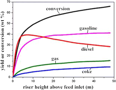
Product yield as a function of riser height
-
2.
The overall activity and selectivity of the catalyst in the conventional riser reactor are seriously insufficient. Based on the online sampling study, axial variation of catalyst activity along the riser reactor was obtained, which indicated that the activity of catalyst rapidly decreased to 40–50 % of the initial level in the feeding zone. The significant decrease of catalyst activity and selectivity leads to aggravated thermal cracking reactions and reduced selectivities of desired products in the second half of the riser reactor. Thus, increasing the catalyst activity, especially in the second half of the riser reactor, is a key matter for developing novel FCC process.
-
3.
The inhibiting effect of competitive adsorption between fresh and cycle oil on desirable reactions aggravates the product distribution. Fresh feedstock contains a considerable amount of high-boiling-point heavy components with large molecular weight, which are easy to crack. However, it is difficult for these components to vaporize, diffuse and adsorb on the active sites. By contrast, the cycle oil contains a large amount of aromatics, which are difficult to crack. But the cycle oil has a narrower boiling range, thus it is easier to vaporize and diffuse to grab the active sites, and influence the adsorption and reaction of the fresh feedstock. Figure 3 compares the weighted results of separated cracking of fresh feed and cycle oil with the consequences of the mixed feeding scheme. It can be found that, at the similar conversion level, when fresh feed and cycle oil were fed and cracked separately, the product distribution significantly improved, lower yields of dry gas and coke, and higher yields of liquid products (LPG + gasoline + diesel) can be achieved.
Fig. 3 
Effect of separate reaction on the product distribution


On the basis of above analysis, we designed two structure-optimized riser reactors to replace the conventional riser reactor [8], formed a novel reaction-regeneration system with two catalyst circulation routes, successfully realized it in commercial scale and finally developed the two-stage riser FCC technology.
Figure 4 shows the schematic diagram of the reaction-regeneration system of the TSR FCC process. The fresh feed after heat-exchanging (preheating) is injected from the bottom of the first stage riser, then contacts with the hot regenerated catalyst, resulting in rapid vaporization and reaction. After about 1.0 s, the oil vapor and coked catalyst are separated. The coked catalyst was stripped by steam, then transported to the regenerator for regeneration. The oil vapor is piped to the fractionator and separated into different fractions, such as dry gas, LPG, gasoline, diesel (or LCO) and heavy cycle oil. The cycle oil is recycled to the bottom of the second stage riser and reacts over the regenerated catalyst (1.0–2.0 s). The oil vapor and coked catalyst are separated at the riser exit. The coke catalyst is regenerated after steam stripping, and the oil vapor is piped to the fractionator with that from the first riser. Thus, both the fresh feed and cycle oil can react over regenerated catalyst with high activity and under the most favorable conditions for maximum light oil yield, respectively.

Schematic diagram of the TSR FCC process
In 2002, the TSR FCC technology was firstly applied in a 100 kt/a industrial unit belonging to the Shtar Science and Technology Group. The conventional riser reactor (45.0 m) was replaced by a 16.0 m riser reactor for the first stage reaction and a 10.7 m riser reactor for the second stage reaction. After the technological renovation and transformation, the dry gas and coke yields decreased 2.7 wt %, while the liquid products yield increased 2.7 wt %. Moreover, the cetane number of diesel increased 7 U.
At present, there are 12 industrial units, including that in the stage of transformation or new construction, applied the TSR technology. The accumulative processing capacity has reached 9 Mt/a, the processing capacity of the largest unit is 1.6 Mt/a.
Multifunctional two-stage riser FCC process
The TSR technology is a great progress of FCC technology. However, as the crudes are getting heavier, the standard of gasoline becomes increasingly strict, and the greater demand of diesel, FCC units are facing many new challenges. Thus, the multifunctional two-stage riser (MFT) FCC process was proposed aimed to enhance the conversion of inferior feedstocks, upgrade FCC gasoline (reduce the olefin content) under minimum loss, and increase the diesel yield [9].
The key problem for increasing diesel yield is that the maximal diesel yield always exists under moderate operating conditions while the feed conversion is very low (Fig. 5). This is because that catalytic cracking is a parallel-sequential reaction [10] and the diesel fraction is more susceptible to sequential cracking reactions than gasoline fractions [11]. In the conventional FCC process, the contradiction of increasing diesel yield and feed conversion is difficult to be resolved, especially when processing inferior feedstocks. The two-stage riser FCC process can solve this problem, using the first stage riser to produce more diesel, but this would lead to the increase of HCO yield. Thus, measures should be taken to enhance the conversion of HCO. As the crackability of HCO is poorer than the fresh feed, higher operating severity (higher reaction temperature and catalyst-to-oil ratio) should be taken to enhance the conversion of HCO.

Relationship of conversion and the diesel yield [9]
One of the major improvements of the MFT FCC process is to efficiently upgrade the FCC gasoline, reducing the olefin content under minimum loss. Four measures were carried out in the MFT process.
-
1.
Recycling the light naphtha selectively. This is because gasoline olefins with a carbon number of seven or higher are easy to crack, while pentene and hexene are difficult to crack under conventional FCC operating conditions [12–15]. Moreover, light naphtha has higher olefin content, which is helpful to restrain the protolytic cracking [16].
-
2.
Decreasing the temperature difference between naphtha and regenerated catalysts. Research found that this operation could restrain the thermal cracking and improve product distribution [17]. It can be conducted by cooling the regenerated catalyst and pre-heating the naphtha feed.
-
3.
Using the partial-coked catalyst to upgrade naphtha. Corma et al. [18] found that the Y zeolite with a coke-on-catalyst content of 1.2 wt % still has enough activity for transforming olefins into paraffins through hydrogen-transfer reaction. Zhang et al. [19] and Yuan et al. [20] found that little coke on catalyst could reduce the dry gas and coke yields and increase the gasoline yield. Thus, this measure is helpful to reduce the naphtha loss.
-
4.
Optimizing the structure of the reactor. Wang et al. [22] and Lu et al. [23] studied the gas-solids flow patterns in the diameter-enlarged reactor by cold model and computational fluid dynamics (CFD) simulation and found that the solid density at the bottom of the enlarged section significantly increased, which is beneficial for bimolecular hydrogen transfer reactions. In the previous work [21], we designed a novel structurally changed reactor with a multinozzle feed system (Fig. 6). Experimental results show that significantly increased olefin conversion and reforming efficiency, as well as improved hydrogen utilization rate can be achieved. Therefore, optimizing the structure of the reactor is also very important.
Fig. 6 
Schematic diagram of the conventional and the novel riser reactor [21]

The schematic diagram of the MFT process is shown in Fig. 7. The fresh feed reacts at moderate operating conditions in the first stage riser to generate more diesel oil. Then the oil gas is piped to the fractionator and separated into dry gas, LPG, light cracking gasoline (LCG), heavy cracking gasoline (HCG), diesel and heavy cycle oil (HCO). The HCO is recycled to the bottom of the second stage riser while the LCG is injected from the bottom of the enlarged section. As the injection of LCG, more heat should be provided by the catalyst. According to the heat balance, the catalyst circulation should be enlarged. Thus, the HCO could be converted at a higher severity without raising the riser outlet temperature, and the LCG could be upgraded at a lower severity over temperature-lowered and partially-coked catalyst. The final gasoline product is the mixture of the HCG from the first fractionator and the full-range gasoline from the second fractionator. It should be noted that this process is designed for experimental research, because in the pilot-scale unit, the two stage riser cannot run simultaneously. If in commercial units, the two risers can share a disengager and fractionator.

Schematic diagram of the MFT FCC process [9]
Simulated experiments were carried out in a pilot scale riser FCC apparatus with HY-CGO as the feedstock and a Y-zeolite based equilibrium FCC catalyst. The results show that, comparing with the TSR FCC process, the MFT FCC process increased feed conversion and diesel yield with 2.2 and 3.3 wt %, respectively, as well as the olefin content of gasoline decreased approximately 17 wt %. Moreover, the cetane number of diesel can be increased. However, the dry gas and coke yields also increased about 1.3 wt %. Thus, it needs to be further improved.
Conclusion
In the conventional RFCC reactor, the overlong reaction time, the fast deactivation of catalyst, and the competitive adsorption and reaction between fresh feedstock and cycle oil would lead to the overcracking of light oil and the deterioration of the product distribution. The proposed two-stage riser FCC process successfully solved these problems, which can decrease the dry gas and coke yields, increase the light oil yield and improve the product quality. To adapt to the new challenges, the multifunctional two-stage riser FCC process was proposed, which can enhance the conversion of heavy oil, increase the diesel yield and further improve the product quality, especially reduce the olefin content of gasoline.
References
Fan Y, Bao XJ, Shi G (2005) Hβ/HZSM-5 composite carrier supported catalysts for olefins reduction of FCC gasoline via hydroisomerization and aromatization [J]. Catal Lett 105(1):67–75
Liu H, Yu J, Fan Y et al (2011) A scenario-based clean diesel production strategy for China National Petroleum Corporation [J]. Pet Sci 8(2):229–238
Rahimi N, Karimzadeh R (2011) Catalytic cracking of hydrocarbons over modified ZSM-5 zeolites to produce light olefins: a review [J]. Appl Catal A 398(1–2):1–17
Sadeghbeigi R (2012) Fluid catalytic cracking handbook: an expert guide to the practical operation, design, and optimization of FCC units [M]. Elsevier, pp 1
Xu CM, Lv LG, Tang QL et al (1997) Catalytic cracking reaction pathway and online sampling in commercial riser [J]. J Univ Pet China (Ed Nat Sci) 21(2):72–75
Yang CH, Shan HH, Zhang JF et al (2007) Shortcoming of conventional RFCC reactor and advantage of TSRFCC technology [J]. J China Univ Pet (Ed Nat Sci) 31(1):127–131
Niu GL, Yang CH, Xu CM et al (2002) Study on reaction pathway in commercial riser of residuum catalytic cracking unit [J]. J Fuel Chem Technol 30(3):249–253
Shan HH, Dong HJ, Zhang JF et al (2001) Experimental study of two-stage riser FCC reactions [J]. Fuel 80(8):1179–1185
Zhang JH, Shan HH, Chen XB et al (2013) Multifunctional two-stage riser catalytic cracking of heavy oil [J]. Ind Eng Chem Res 52(2):658–668
Wojciechowski BW, Corma A (1986) Catalytic cracking: catalysts, chemistry, and kinetics [M]. Marcel Dekker, New York
Wang G, Lan XY, Xu CM et al (2009) Study of optimal reaction conditions and a modified residue catalytic cracking process for maximizing liquid products [J]. Ind Eng Chem Res 48(7):3308–3316
den Hollander MA, Wissink M, Makkee M et al (2002) Gasoline conversion: reactivity towards cracking with equilibrated FCC and ZSM-5 catalysts [J]. Appl Catal A 223(1–2):85–102
Yuan YX, Yang CH, Shan HH et al (2005) Study on the reaction mechanism of olefins on FCC catalyst [J]. J Fuel Chem Technol 33:435–439
Verstraete J, Coupard V, Thomazeau C et al (2005) Study of direct and indirect naphtha recycling to a resid FCC unit for maximum propylene production [J]. Catal Today 106(1–4):62–71
Buchanan JS (1998) Gasoline selective ZSM-5 FCC additives: model reactions of C6–C10 olefins over steamed 55:1 and 450:1 ZSM-5 [J]. Appl Catal A 171(1):57–64
Wielers AFH, Vaarkamp M, Post MFM (1991) Relation between properties and performance of zeolites in paraffin cracking [J]. J Catal 127(1):51–66
Wang G, Yang GF, Xu CM et al (2008) A novel conceptional process for residue catalytic cracking and gasoline reformation dual-reactions mutual control [J]. Appl Catal A 341(1–2):98–105
Corma A, Melo FV, Sauvanaud L et al (2005) Light cracked naphtha processing: controlling chemistry for maximum propylene production [J]. Catal Today 107–108:699–706
Zhang X, Chen XB, Zhang JF et al (2005) Study on process conditions for decreasing FCC naphtha olefin content in riser [J]. Pet Refin Eng 35(4):8–12
Yuan YX, Yang CH, Shan HH (2006) Study on olefins reduction of gasoline on FCC semi-regenerated catalysts with different coke contant [J]. J China Univ Pet (Ed Nat Sci) 30:109–112
Zhang JH, Shan HH, Chen XB et al (2013) In situ upgrading of light fluid catalytic cracking naphtha for minimum loss [J]. Ind Eng Chem Res 52(19):6366–6376
Wang X, Gao S, Xu Y et al (2005) Gas–solids flow patterns in a novel dual-loop FCC riser [J]. Powder Technol 152(1–3):90–99
Lu B, Wang W, Li JH et al (2007) Multi-scale CFD simulation of gas–solid flow in MIP reactors with a structure-dependent drag model [J]. Chem Eng Sci 62(18–20):5487–5494
Acknowledgments
The authors acknowledge the financial support provided by the National Basic Research Program of China (2012CB215006), the Fundamental Research Funds for the Central Universities (13CX05002A), and the Graduate Student Innovation Project of China University of Petroleum (CX2013029).
Author information
Authors and Affiliations
Corresponding author
Rights and permissions
Open Access This article is distributed under the terms of the Creative Commons Attribution License which permits any use, distribution, and reproduction in any medium, provided the original author(s) and the source are credited.
About this article

Cite this article
Zhang, J., Shan, H., Chen, X. et al. Multifunctional two-stage riser fluid catalytic cracking process. Appl Petrochem Res 4, 395–400 (2014). https://doi.org/10.1007/s13203-014-0079-5
Received:
Accepted:
Published:
Issue Date:
DOI: https://doi.org/10.1007/s13203-014-0079-5