
Abstract
Silicon has recently been recognized as a potentially attractive phase change material for ultra-high-temperature latent heat thermal energy storage (LHTES) and conversion systems. It has been proposed that the utilization of silicon’s latent heat should drastically increase the performance of LHTES devices in terms of operational temperatures and available energy density. Nevertheless, in order to ensure a high reliability and long lifetime of the system, proper ceramic materials that are able to withstand contact heating and cooling cycles during consecutive melting/solidification steps need to be examined and selected. Previously, we have documented that hexagonal boron nitride (h-BN) is the only ceramic that shows non-wettability and limited reactivity in contact with molten silicon at temperatures up to 1650°C. In this work, we present for the first time the results of experimental research on the performance of a Si/h-BN system upon cycling melting/solidification processes. For this reason, the Si/h-BN couple was subjected to a sessile drop experiment containing 15 cycles of heating/cooling between 1300°C and 1450°C. During the test, temperatures of specific events as well as contact angle values were recorded. After the test, the structure and surface morphology of the solidified Si/h-BN couple were characterized by means of scanning electron microscopy.
Introduction
Latent heat thermal energy storage (LHTES)-based devices are utilized to produce electricity by converting heat absorbed/released during phase transformations of a material (a so-called phase change material; PCM) subjected to cyclic heating/cooling schemes. The current and perspective application fields of LHTES devices cover, for example, terrestrial or space solar energy systems.1,2,3 Very recently, it has been proposed that the introduction of silicon as the PCM should significantly overcome limitations of state-of-the-art molten salt-based LHTES systems, both in terms of operational temperatures and available energy density.2 However, in order to move the Si-based LHTES system from a designer’s desk to real industrial applications, the performance of ceramics intended to be used for building the PCM container has to be a priori experimentally evaluated. The basic assumption for the selection of proper ceramics is their “inertness” during long-term storage of solid/liquid state silicon. In other words, the selected ceramic material should exhibit a non-wetting behavior and a limited degradation (a lack of reactively formed interfacial products due to a direct reaction between Si and contacting refractory). However, from a literature review,4,5 almost all conventional ceramic materials, such as oxides, borides, carbides or nitrides, are well-wettable by molten silicon (i.e., they are characterized by contact angle θ values below 90°). The one reported exception in this field is hexagonal boron nitride (h-BN) that shows non-wettability at temperatures up to 1500°C.5 In our previous work,6 we documented that this non-wetting behavior is maintained at temperatures up to 1650°C, while the high-temperature interaction mechanism in the Si/h-BN system is dominated by a slight dissolution of the h-BN ceramic in molten Si, followed by the reprecipitation of h-BN platelets during cooling. Furthermore, there were no continuous products reactively formed at the Si/h–BN interface. Since the observed high-temperature performance of the h-BN ceramic in contact with liquid Si allows for its preliminary selection as a good candidate for the PCM container, further examinations still need to be performed in order to assess its reliability upon consecutive melting/solidification steps.
Therefore, the main purpose of this work is to experimentally evaluate the wettability and reactivity in the Si/h-BN system subjected to high-temperature cycling phase changes.
Materials and Methods
The materials investigated were ultra-high-purity silicon (7 N) and the commercially available hot-sintered h-BN ceramics (Henze HeBoSint D100, Germany). More details on the examined materials and applied sample preparation routes are described elsewhere.6 The Si/h-BN couple was subjected to sessile drop experiments performed by using an experimental complex for the investigation of high-temperature capillarity phenomena, described elsewhere.7
The applied testing procedure (schematically shown in Fig. 1) included 15 cycles composed of (1) heating to 1450°C at a rate of 15°C/min and holding for 5 min, and (2) cooling to 1300°C at a rate of 10°C/min.

Temperature profile of the wettability test including 15 heating/cooling cycles of the Si/h-BN couple between 1300°C and 1450°C with intermediate cooling to room temperature
After 10 cycles, the Si/h-BN couple was cooled to room temperature, and then subjected to 5 more cycles of heating/cooling. Although a predicted real heating/cooling scheme in the Si-based LHTES device will involve much lower heating/cooling rates, the temperature profile used was applied to examine the materials’ behavior under “forced” conditions which should accelerate their potential degradation. The test was started under ultra-high vacuum conditions (p = 10−7 mbar), and then, during the first cycle, a static argon (p = 850–900 mbar) was introduced at 800°C in order to suppress evaporation of the silicon. During the test, the images of the Si/h-BN couple were in situ recorded by a high-speed camera (at 100 frames per s), and then used to compile a video and calculate the contact angle values. Moreover, real-time visual observation of the couple was made during each heating/cooling cycle in order to determine the corresponding melting and solidification temperatures.
When the test was over, the solidified couple was removed from the chamber and subjected to a structural characterization by using an FEI Scios™ field emission gun scanning electron microscope (SEM) coupled with energy dispersive x-ray spectroscopy (EDS). The examinations were performed on both top views and cross-sectioned samples.
Results and Discussion
Wetting Behavior During Cycling Si Melting/Solidification Processes
The fast-forward video recorded during the test is available as the Electronic Supplementary Material 1. What should be noted is that the silicon showed a high cyclic stability in terms of onset and offset temperatures of melting and solidification processes (Fig. 2a). In fact, the melting offset temperatures were close to the theoretical melting point of Si (Tm = 1414°C), and only a slight decrease was observed during the consecutive cycles. As was also expected, a significant undercooling effect was noted. It was documented that in each cycle the solidification was finished at a temperature around 1345°C, thus giving ∆T ~ 70°C. The change of contact angle after melting and holding the Si drop in consecutive cycles is presented in Fig. 2b, while a set of corresponding Si drop/h-BN substrate images taken after 5 min holding at 1450°C in each cycle, is presented in Fig. 3. It was found that, during the whole experiment, the contact angle values were within the non-wettability regime (i.e., the θav was higher than 90°). However, it was noted that (1) in the 10th cycle, a substantial increase of contact angle from θav ~ 100° to θav ~ 125–130° took place (Fig. 2b) and (2) the Si drop was spontaneously moved along the substrate surface during subsequent cycles (Fig. 3b).

The recorded temperature ranges of melting and solidification of Si (a). The average contact angle θav values calculated for Si/h-BN couple during consecutive cycles (b)

(a) A schematic showing exemplary Si drop/h-BN substrate image in situ recorded after 5 min holding at 1450°C in each cycle. (b) Real-time images captured in each cycle; dotted line on images #10–15 denotes the position of the drop formed in the first cycle
Structural Characterization of the Si/h-BN Couple After Melting/Solidification Cycles
A macroscopic view of the Si/h-BN couple after 15 cycles of melting/solidification is shown in Fig. 4a. The presence of some modification of the h-BN surface related to a spontaneous in situ detachment and movement of the Si drop can be distinguished. The results of SEM examinations of this area (Fig. 4b, c) revealed the presence of fine h-BN platelets having different sizes. A difference in the size of the platelets reflects the spontaneous movement path of the Si drop (see Fig. 3b); the smallest were located in the outer zone, while their size increased towards the central part of the h-BN substrate area initially covered by the Si drop. The results of the EDS analysis (Fig. 4d) confirmed the existence of small Si particles (so-called “daughter droplets”) that were left behind during movement of the main (“mother”) Si drop.

A macroview of the solidified Si/h-BN couple after 15 melting/solidification steps (a). SEM top-view images showing the part of h-BN substrate that was initially below the Si drop, and then revealed in consecutive cycles (b, c). The EDS mapping confirming an existence of small Si droplets (“daughter droplets”) being left after the movement of the main (“mother”) drop (d)
What is important is that there is no evidence for the formation of any interfacial continuous product layers (e.g., silicon nitride Si3N4, as was suggested in Ref. 8. After that, the cross-section of Si/h-BN couple was prepared by using a precise metallographic cutter, while cold-mounting in epoxy resin was first applied to protect the sample (Fig. 5).

Sketch of sample preparation for microscopic inspections of cross-sectioned Si/h-BN couple
The results of SEM inspections carried out on the cross-sectioned sample documented (1) the formation of a platelets zone (with a thickness of ~ 150 µm) in the h-BN substrate’s subsurface area (Fig. 6a); (2) a slight change of the chemistry of initially ultra-high-purity Si towards a Si-B alloy reflected by the presence of a very few Si + SiB3 eutectic features between the Si grains (Fig. 6b); and (3) a lack of any new products formed at the interface, except for some single needle-like particles observed on the drop side (Fig. 6c). Based on the measured increased content of B and N, they were recognized as h-BN platelets that were detached from the substrate during the thermocycling experiment.

The results of SEM/EDS examinations of the cross-sectioned Si/h-BN couple after 15 melting/solidification steps showing: (a) formation of platelets zone (with a thickness of ~ 150 µm) in the h-BN substrate’s subsurface area; (b) a slight change of chemistry of initially ultra-high-purity Si towards a Si-B alloy reflected by the presence of a very few Si + SiB3 eutectic features; (c) the EDS linear analysis confirming the existence of some single detached h-BN platelets on the Si drop side
Finally, based on the results of the conducted high-temperature thermocycling test and the structural characterizations of the obtained materials, the following interaction mechanism in the Si/h-BN system during consecutive melting/solidification processes of Si might be proposed. As in the case of our previous experiment,6 the interaction is dominated by a slight dissolution of the h-BN substrate in the molten Si, followed by the reprecipitation (a re-growth) of the h-BN platelets during solidification. Consequently, boron from the h-BN substrate easily diffuses into the molten Si, while nitrogen is released through the gas/liquid interface as a gaseous product due to its very low solubility in Si. By taking into account an extremely high latent heat of boron,2 an introduction of small amounts of this element into the PCM candidate should be considered as beneficial in terms of the performance of LHTES devices. Interestingly, in the present work, it has also been documented that the in situ modification of the h-BN surface morphology affects the wetting characteristics in the Si/h-BN system. Most probably, the observed increase of contact angle in the 10th cycle and the movement of Si drop in subsequent cycles is an effect of its uplifting and mechanical pinning on regrown h-BN platelets. Thus, based on the obtained results, the involved interaction mechanism is described as follows:
-
1.
A Si piece is placed on a h-BN substrate having a smooth and flat surface. During the first melting at the temperature of 1414°C, initially Si does not wet the h-BN substrate. However, when the testing temperature is increased to 1450°C, the h-BN substrate is slightly dissolved in the molten Si and the contact angle decreases (Fig. 7a).
Fig. 7 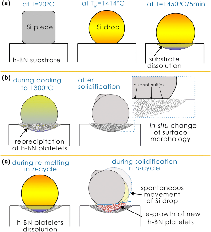
Schematic drawings of interaction in Si/h-BN system upon cyclic heating/cooling within temperature range of 1300–1450°C. The drawings show: (a) melting and holding of Si/h-BN at 1450°C/5 min in the first cycle; (b) a re-precipitation of h-BN crystals having platelet-like morphology during cooling to 1300°C; (c) a spontaneous detachment and movement of the Si drop upon multiple melting/solidification processes. More details are shown in the text
-
2.
Upon cooling from 1450°C to 1300°C, the h-BN crystals having a platelet-like morphology reprecipitate in the dissolved substrate area. Since the reprecipitation process takes place at a temperature higher than that needed for the full solidification of the Si drop, a new solid/solid interface is formed in situ. What is important is that a needle-like morphology of grown interfacial h-BN crystals combined with a lack of wettability with molten Si gives a discontinuous contact with the Si drop (Fig. 7b). Furthermore, due to the fact that the contacting substrate surface loses its flatness and smoothness, the recorded contact angles are far from the applicability of Young’s equation, and thus they should be treated as apparent in nature. Similar findings on recorded contact angles were noted in our recent work,9 in which open (and near-surface) porosity was reactively formed in the h-BN-based composite subjected to contact heating with molten Si at an ultra-high temperature.
-
3.
During consecutive melting/solidification cycles the Si/h-BN interface undergoes further changes. The pre-existing h-BN platelets are cyclically dissolved in contact with molten Si, and the new ones are reprecipitated upon cooling to 1300°C. This behavior results in a prominent differentiation of h-BN platelet size: the largest were observed in areas subjected to the longest direct contact with molten Si. As a consequence of the highly developed inhomogeneous surface topography, the Si drop can undergo a spontaneous “self-detachment” movement (Fig. 7c).

This behavior is analogous to that described by Liang et al.10 showing a superhydrophobicity of highly crystallized h-BN microplatelets formed in accordance with a “surface microarchitecture” approach. They have documented that the presence of such morphological features significantly increases the contact angle value of a water drop on a h-BN substrate, i.e., it gives a so-called “lotus leaf” effect. What is important is that in such a case a lack of perfectly flat and rigid surface conditions makes the recorded contact angle values far from equilibrium, i.e., they are apparent in nature. Although in the present work the wetting characteristic was similar, it should be noted that the orientation of the platelets reprecipitated in consecutive cycles is rather random, so that it is quite hard to exactly predict the behavior of the Si/h-BN system during cycling melting/solidification processes. Nevertheless, in the view of the non-wettability requirement for the selection of refractories for the PCM container, the in situ formation of fine h-BN crystals having a platelet-like morphology on the contacting ceramic surface is clearly favorable.
Conclusion
In this work, the performance of a commercial h-BN ceramic in contact with silicon upon its cycling melting/solidification was experimentally examined for the first time. For this purpose, the Si/h-BN couple was subjected to a sessile drop experiment containing 15 cycles of heating/cooling between 1300°C and 1450°C. It was found that Si on the h-BN substrate shows a high cyclic stability in terms of the onset and offset temperatures of melting and solidification processes. It was also documented that the interaction mechanism in the Si/h-BN system is dominated by a slight dissolution of the h-BN in molten Si followed by the reprecipitation of h-BN platelets during cooling. Consequently, although the Si/h-BN systems is characterized by a non-wettability behavior, the regrown platelets randomly alter the surface morphology (and also its smoothness and flatness) in each melting/solidification cycle. As was experimentally documented in this work, such behavior can lead to a prominent change of wetting characteristics of a h-BN refractory being in a contact with molten Si. Additionally, in the view of possible applications of h-BN as PCM container material for Si-based LHTES systems, both in situ slight changes of silicon chemistry towards Si-B alloys as well as the increase of contact angle during consecutive cycles should be considered as beneficial.
References
A. Datas and A. Marti, Sol. Energ. Mat. Sol. C 161, 285 (2017).
A. Datas, A. Ramos, A. Martí, C. del Cañizo, and A. Luque, Energy 107, 542 (2016).
A. Datas, A.B. Cristobal, C. del Cañizo, E. Antolín, M. Beaughon, N. Nikolopoulos, A. Nikolopoulos, M. Zeneli, N. Sobczak, W. Polkowski, M. Tangstad, J. Safarian, D.M. Trucchi, A. Bellucci, M. Girolami, R. Marx, D. Bestenlehner, S. Lang, A. Vitulano, G. Sabbatella, A. Martí, and A.I.P. Conf, Proc. 2033, 170004 (2018).
Z. Yuan, W.I. Huang, and K. Mukai, Appl. Phys. A-Mater. 78, 617 (2004).
B. Drevet and N. Eustathopoulos, J. Mater. Sci. 47, 8247 (2012).
W. Polkowski, N. Sobczak, R. Nowak, A. Kudyba, G. Bruzda, A. Polkowska, M. Homa, P. Turalska, M. Tangstad, J. Safarian, E. Moosavi-Khoonsari, and A. Datas, J. Mater. Eng. Perform. 27, 5040 (2018).
N. Sobczak, R. Nowak, W. Radziwill, J. Budzioch, and A. Glenz, Mater. Sci. Eng., A 495, 43 (2008).
B. Drevet, R. Voytovych, R. Israel, and N. Eustathopoulos, J. Eur. Ceram. Soc. 29, 2363 (2009).
W. Polkowski, N. Sobczak, A. Polkowska, R. Nowak, A. Kudyba, G. Bruzda, D. Giuranno, A. Generossi, B. Pacci, D.M. Trucchi, Metall. Mater. Trans. A:, in press, (2018), https://doi.org/10.1007/s11661-018-5035-z.
J. Liang, Y. Huang, J. Lin, C. Feng, C. Yu, X. He, Z. Yan, W. Zhai, and C. Tang, J. Alloy. Compd. 705, 749 (2017).
Acknowledgements
The project AMADEUS has received funds from the European Union’s Horizon2020 research and innovation program, FET-OPEN action, under grant agreement 737054. The sole responsibility for the content of this publication lies with the authors. It does not necessarily reflect the opinion of the European Union. Neither the REA nor the European Commission are responsible for any use that may be made of the information contained therein.
Author information
Authors and Affiliations
Corresponding author
Ethics declarations
Conflict of interest
The authors declare that they have no conflict of interest.
Additional information
Publisher's Note
Springer Nature remains neutral with regard to jurisdictional claims in published maps and institutional affiliations.
Electronic supplementary material
Below is the link to the electronic supplementary material.
11837_2019_3364_MOESM1_ESM.avi
Supplementary material 1 (the video clip recorded during the multi-cycling wettability test) is available in the online version of this article. (AVI 3624 kb)
Rights and permissions
Open Access This article is distributed under the terms of the Creative Commons Attribution 4.0 International License (http://creativecommons.org/licenses/by/4.0/), which permits unrestricted use, distribution, and reproduction in any medium, provided you give appropriate credit to the original author(s) and the source, provide a link to the Creative Commons license, and indicate if changes were made.
About this article

Cite this article
Polkowski, W., Sobczak, N., Polkowska, A. et al. Silicon as a Phase Change Material: Performance of h-BN Ceramic During Multi-Cycle Melting/Solidification of Silicon. JOM 71, 1492–1498 (2019). https://doi.org/10.1007/s11837-019-03364-4
Received:
Accepted:
Published:
Issue Date:
DOI: https://doi.org/10.1007/s11837-019-03364-4