
Abstract
The MAJIS (Moons And Jupiter Imaging Spectrometer) instrument on board the ESA JUICE (JUpiter ICy moon Explorer) mission is an imaging spectrometer operating in the visible and near-infrared spectral range from 0.50 to 5.55 μm in two spectral channels with a boundary at 2.3 μm and spectral samplings for the VISNIR and IR channels better than 4 nm/band and 7 nm/band, respectively. The IFOV is 150 μrad over a total of 400 pixels. As already amply demonstrated by the past and present operative planetary space missions, an imaging spectrometer of this type can span a wide range of scientific objectives, from the surface through the atmosphere and exosphere. MAJIS is then perfectly suitable for a comprehensive study of the icy satellites, with particular emphasis on Ganymede, the Jupiter atmosphere, including its aurorae and the spectral characterization of the whole Jupiter system, including the ring system, small inner moons, and targets of opportunity whenever feasible. The accurate measurement of radiance from the different targets, in some case particularly faint due to strong absorption features, requires a very sensitive cryogenic instrument operating in a severe radiation environment. In this respect MAJIS is the state-of-the-art imaging spectrometer devoted to these objectives in the outer Solar System and its passive cooling system without cryocoolers makes it potentially robust for a long-life mission as JUICE is. In this paper we report the scientific objectives, discuss the design of the instrument including its complex on-board pipeline, highlight the achieved performance, and address the observation plan with the relevant instrument modes.
1 Introduction
The JUICE mission selected in 2012 is the first large-class mission under the Cosmic Vision Programme of the European Space Agency (Grasset et al. 2013). After successful launch on 14 April 2023 followed by a 8.25-year cruise and insertion into Jupiter’s orbit in July 2031, it will provide a comprehensive survey of the Jupiter system, with special emphasis on the three ocean-bearing worlds, Ganymede, Europa, and Callisto as planetary bodies and potential “habitats” for the two first. The Galilean satellites exemplify solar system objects with shared origins and initial conditions, yet exhibiting an extreme diversity today, reflecting the complexity of the processes which shaped their evolution. Their detailed analysis therefore offers potential breakthroughs in the evolutionary processes of solar and stellar systems.
Ganymede has been selected for enhanced investigation with 12 flybys (including 8 close flybys for which the spacecraft altitude will be below 1500 km) followed by a 9-month orbital phase starting in December 2034; Ganymede will thus provide an unprecedented target for deciphering the nature, evolution and potential habitability of icy worlds, while enabling the study of its unique magnetic and plasma interactions with the surrounding Jovian environment. For Europa, with two planned flybys, the focus will be on the surface and sub-surface chemistry thought to be essential for life, with an emphasis on the detection of organic molecules and endogenic species. The characterization of specific surface features with a special attention on the most active zones could lead to the identification of potential candidate sites for future in situ exploration. By observing the ancient highly cratered surface of Callisto during 21 flybys, JUICE will also add new constraints on a possible subsurface ocean as well as on the physical processes that occurred in the early Jovian system, leading to the unique erosion and gardening of its densely cratered plains. The study of the diversity of the satellite system will be enhanced by additional remotely sensed information on Io, the smaller moons and the rings. During the nominal ∼3.5-year duration of the Jovian tour, the mission will also focus on characterizing Jupiter’s atmosphere (circulation, meteorology, chemistry and structure from the cloud tops up to the thermosphere) and magnetosphere (three-dimensional properties of the magnetodisc and coupling processes), and their interaction with the Galilean satellites. These extended observations of the planet will last long enough to monitor the evolving weather systems and the mechanisms that transport energy, momentum and material between the different layers. JUICE science objectives and an overview of the S/C and mission operations are described in detail in the respective other articles of this collection.
MAJIS is a visible and infrared hyperspectral imager operating from 0.5 μm to 5.5 μm. It is one of the four remote sensing instruments on the JUICE payload (see the respective other articles of this collection). This set of instruments will perform remote sensing observations from UV to millimeter wavelengths to characterize the geology, the surface composition and the exospheres of satellites as well as the Jovian atmosphere at high spatial and spectral resolution.
The MAJIS instrument is based on a heritage from similar instruments, most developed by the same partners, onboard previous and currently active planetary missions. However, MAJIS benefits from several technical improvements (in particular the number of spatial and spectral elements) customized to achieve the unique goals of the JUICE mission. A similar instrument (Mapping Imaging Spectrometer for Europa – MISE, Blaney et al. 2023) is part of the payload of the Europa Clipper mission of NASA. It will collect spectral measurements of the Europa surface in the same timeframe as MAJIS providing an unique opportunity to coordinate the analyses between MAJIS and MISE.
The scientific and technical overview of the MAJIS investigation is described in this review. The MAJIS instrument was built by a French-Italian consortium led by Institut d’Astrophysique Spatiale in Orsay, France with the support of CNES and ASI. Specifically, CNES has funded the MAJIS’ detectors and their proximity electronics, provided ad hoc technical support (in particular for electronics design and flight software) and supported on a case-by-case basis the technical resolution of anomalies that occurred during the instrument development. The Italian contribution comes from the Istituto Nazionale di Astrofisica (INAF) with the support of the Italian Space Agency (ASI) and the industrial contract for the optical head from Leonardo S.p.A. in Florence. Belgian laboratories supported by Belspo were involved in the characterization of the MAJIS detectors including radiation effects.
The review article is structured in seven main sections: (1) the science background of the MAJIS objectives, and their translation into imaging spectroscopic measurements; (2) the driving requirements for the instrument design and overview; (3) the detailed optical, mechanical and electronic design of the MAJIS instrument; (4) overview of instrument testing, calibration, and pre-launch performances; (5) onboard processing of acquired data with the MAJIS software; (6) the observing strategy taken into account the versatility of the JUICE trajectory and the MAJIS capabilities; and (7) the ground support for the operations and data analysis.
2 Science Objectives
2.1 Investigation Overview
The JUICE Science Study Team recommended several high-level investigations to characterize the three icy moons and the Jupiter system (Grasset et al. 2013). MAJIS has been designed to address several of the prime objectives (Table 1). In the table below, we introduce the major investigations of MAJIS with respect to the icy satellites (both surfaces and exospheres) as well as Jupiter’s atmosphere and its aurorae. More details on the science objectives, related observations and retrieval of physical parameters are given in Sects. 2.2 (satellites) and 2.3 (Jupiter).
Do Ganymede, Europa and Callisto lie along a continuum of surface activity and composition resulting from their size or distance to Jupiter? Or must distinct endogenic or exogenic processes/events be implied to account for their present diversity? Analyzing their surface in the visible/infrared range will make it possible to address several key questions: how do they interact with their environment, and how do their properties record endogenous processes linked to the geological activity coupled to exogenous processes? Studying their comparative composition at high spatial resolution will provide new insight into the geochemical state of the surface and sub-surface as well as the space environment.
One of the major scientific requirements of JUICE is the spectral sampling needed to resolve the narrowest signatures in the laboratory spectra of the non-water ice materials expected on the surface of the icy Galilean satellites, in particular hydrated materials. With high spectral resolution, MAJIS can distinguish between different compounds showing similar spectral features and accurately map their abundance on the surface with reduced uncertainties.
The state of water ice and the average grain size of the icy surface can be inferred from the analysis of near-infrared (NIR) spectra. Using spectral markers of ice crystallinity in the NIR range such as the Fresnel peak at 3.1 μm, the distribution of crystalline versus amorphous water ice can be mapped on the surfaces of the icy Galilean satellites, particularly Ganymede and Callisto. Average grain sizes of pure icy surfaces can be also inferred by analyzing the 1.25-1.5-2.0 μm band depths and the spectral continuum profile between 3 and 4 μm, supported by radiative transfer modeling, with finer grains showing fainter band depths and higher continuum level in this region (Filacchione et al. 2012). However, a major difference in the icy Galilean satellites is the presence of hydrated minerals or other hydrates, which can mimic the 1.5 and 2.0 μm water ice absorption bands, so that mixtures of pure granular water ice and salts must be considered in computing spectral indices (Stephan et al. 2020). The four Galilean satellites are also known to have tenuous atmospheres/exospheres (McGrath et al. 2004), and their properties are indicative of surface processes and composition. Characterizing the composition of the bound and escaping neutral atmospheres of the Galilean satellites is one of the investigations of the JUICE mission.
MAJIS will acquire low spatial resolution data (between 10 and 5 km/px) during the inbound and outbound phases of the flybys, mapping large areas to both characterize a large number of high-interest sites of the icy satellites and to reveal leading/trailing asymmetries potentially due to contamination by exogenous material. During the closest approach phases, the spatial sampling will be less than 100 m/px. Extended regional mapping of Ganymede is foreseen during the GCO5000 and GEO5000 phases (as defined in Sect. 7.1), complemented by high spatial resolution observations during the GCO500 phase. The compositional information from the Galilean satellites, obtained from high spatial resolution (see Table 2 to Table 4) and high Signal to Noise Ratio (SNR) observations of small spatial areas (targeting specific regions or geological features) will thus be entirely complementary to global mapping at reduced resolutions. The ability to correlate compositional units with geological structures at different scales shall be one of the key objectives of MAJIS. Moreover, the combination of the high spatial/spectral images acquired by MAJIS, with unprecedented high spatial resolution imagery with JANUS and the ice-penetrating radar exploration with RIME constitutes a unique feature of the JUICE combined science, key to unraveling the surface-subsurface exchange processes on Ganymede and the other two icy satellites (e.g., Tosi et al. 2023). Regarding to the characterization of their exosphere, MAJIS shall complement the UV imaging spectrometer and particle instruments in achieving this goal, by performing limb scans at high phase angles to highlight non-local thermodynamic emissions (non-LTE) of trace compounds. Spectral imaging of Ganymede’s aurorae as well as stellar occultations in the VIS-IR range are also planned to complement similar observations carried out in the UV domain.
Besides the icy satellites, Io is a target of great interest because of its extensive volcanic activity, the strongest in the solar system, and its influence on the Jovian system, in particular its magnetosphere. Although close Io flybys of JUICE are not planned, disk-resolved observations carried out from distance (typically ∼106 km) can be achieved by MAJIS. These observations will monitor the volcanic activity of Io, its hemispheric thermal emission, and determine the composition of the different surface materials on a regional scale as well as their induced volatile cycle.
In summary, MAJIS will determine the surface composition of the icy Galilean satellites providing major improvement in terms of spectral (and thus compositional) and spatial resolution. Coverage of Ganymede and Callisto at scales up to a few km (which cannot be obtained from the ground even with the extremely large telescopes) will be much more extended than that of previous space missions. Targeted observations at high spatial and spectral resolutions coupled with a good SNR (>100 on average for Ganymede and Callisto, and >30 for Europa in the 3.2-3.6 μm range which is most critical for the detection of organics), will offer a reliable identification and discrimination of non-water-ice constituents on the icy satellite surfaces, and a consolidated quantification of their abundance to be coupled with geological features in a wide range of spatial scales (down to a spatial sampling of 100 m and possibly less on a number of well selected targets on Ganymede).
The visible and infrared spectrum spans both reflected sunlight, auroral emission, and thermal emission from the deep atmosphere, enabling sounding of the atmosphere from the cloud-forming weather-layer into the ionosphere and thermosphere. The MAJIS design is thus suited to study Jupiter’s tropospheric meteorology, dynamics, clouds, chemistry, and its aurorae, and to generate a long-term database of atmospheric/auroral variability over the length of the Jupiter tour. The orbit of JUICE will allow MAJIS to study Jupiter’s atmosphere in all local time conditions, improving on the limited local time coverage of the Jovian Infrared Auroral Mapper (JIRAM) due to the Juno mission profile. The Instantaneous Field-Of-View (IFOV) of MAJIS will provide a spatial resolution of ∼150 km (at the reference 1-bar level that represents the zero-altitude surface of Jupiter’s atmosphere) from the distance of Ganymede’s orbit.
The MAJIS spectral range covers the \(\mathrm{H}_{3}^{+}\) emission signatures around 2, 3.5, 3.67 and 5 μm that are strongly enhanced in the Jovian aurora (Drossart et al. 1989). The MAJIS observations will extend the JIRAM dataset (Adriani et al. 2017a,b) in terms of temporal coverage and spectral resolution. The mapping capabilities of MAJIS are ideally suited to monitor the overall auroral activity and phenomenology of the polar atmosphere during the high-inclination phases and to correlate them to in situ measurements from the magnetometer and plasma/neutral packages. The observations will also be coordinated with those of UVS to study the morphological differences between the instantaneous mapping of the incident particle flux (UV, visible) and the slower atmospheric response of the \(\mathrm{H}_{3}^{+}\) emission (as exemplified with the Juno mission in e.g. Gérard et al. 2023). Whenever possible, MAJIS stellar occultations by Jupiter’s disk will contribute to constrain the mixing ratio of methane in the stratosphere as well as the variability of atmospheric temperatures. Observations of the nightside hemisphere will be of interest for possible detections of lightnings (Smith et al. 1979; Becker et al. 2020), Transient Luminous Events (Giles et al. 2020) and nightglow emissions.
Jupiter’s atmospheric circulation and cloud systems will be continuously monitored by synoptic tracking of features over large regions of the planet (disk scan, see Sect. 2.3.3). Particular attention will be devoted to the study of dynamical regimes associated with circulations on the scale of Jupiter’s belts and zones (e.g., the zonal winds, Fletcher et al. 2020), vortices of various scales, and the occurrence of plumes and storms (Sánchez-Lavega et al. 2018; Sindoni et al. 2017). The high latitudes reached during the Callisto flybys will provide mapping of reflective aerosols that cover the polar domain, as well as the morphology and dynamics of the circumpolar cyclones (Adriani et al. 2018). The high number of the spectral sampling points in MAJIS data will allow the effective application of statistical analysis methods (such as principal component analysis and various classification schemes) to detect, for example, subtle differences in aerosol properties, with special attention to the nature of chromophores.
MAJIS extends to shorter wavelengths (0.5 μm) than JIRAM (which cuts on at 2 μm), giving access to the short-wave reflected sunlight that has been also previously used, besides Earth-based and space-based observations, by close investigations from Galileo/NIMS and Cassini/VIMS. These short wavelengths allow MAJIS to better constrain the composition and size distribution of aerosols within the different cloud decks, by comparing radiances observed in different CH4 spectral windows and observations of the same region at different phase angles (Sromovsky and Fry 2002; Migliorini et al. 2023). The JUICE orbit will enable observations at a variety of emission, phase, and incidence angles (Fletcher et al. 2023, this collection), which will ultimately better constrain the scattering properties and locations of the upper tropospheric and stratospheric hazes, and thus provide insights on their chemical composition and origin, in particular the condensation and photochemical phenomena that produce potential cloud-condensation nuclei. Further constraints on the aerosol properties at higher altitudes will be derived from the modeling of stellar extinction during occultation measurements.
Observations in the 5 μm atmospheric window probe thermal emission from relatively cloud-free regions, providing insights into the composition of Jupiter’s atmosphere from the upper troposphere down into the cloud-forming region, potentially down to approximately 7 bars (e.g., Bjoraker et al. 2018; Grassi et al. 2010, 2021). Thermal emission from this spectral region is shaped by both condensable volatiles (e.g., ammonia and water), as well as species that are in chemical disequilibrium, mixed upwards from the deeper and warmer troposphere (e.g., phosphine, arsine, germane, and carbon monoxide). Ammonia is sensed both above (where photochemical depletion occurs) and below its condensation cloud deck (where ammonia should be well-mixed), but has been shown to be depleted and to vary on the scales of the belts and zones). Water is sensed only above the clouds, following a saturated vapor pressure curve with a relative humidity that varies with location (Grassi et al. 2017). Whilst these cannot be used to place constraints on the bulk composition of Jupiter, they can be used to investigate the microphysical and dynamical processes at work in the cloud-forming region, particularly in association with maps of lightning activity in Jupiter’s troposphere. These are supported by the use of disequilibrium species as tracers for vertical mixing and photochemical destruction (e.g., Irwin et al. 1998; Fletcher et al. 2009; Grassi et al. 2017, 2021). Both the volatiles and the disequilibrium species vary from belts to zones, and exhibit sharp contrasts associated with vortices, convective plumes and wave-like patterns such as the 5- μm hotspots on the boundary between Jupiter’s Equatorial Zone and North Equatorial Belt (NEB). MAJIS will determine the spatial variability of vertical mixing processes throughout Jupiter’s weather layer, and above by mapping aerosols using reflected light and thermal emission, combined with mapping of gaseous composition (particularly with the extension of MAJIS to large IR wavelengths, further than any previous space-based mapping spectrometer).
2.2 Icy Satellites: Key Questions and Measurement Objectives
MAJIS will target the surface and the thin atmosphere/exosphere of each of the icy satellites at various spatial resolutions to determine their compositional properties and to place these properties into geological context. Following an introduction to the scientific background, the relationship of these investigations and the major JUICE science objectives is described below and compiled in Table 2 to Table 4.
2.2.1 Surfaces
Ice Characterization
Most of the high-resolution compositional information available to date on the surface composition of the icy moons has been collected from 1995 to 2003 by the Near-Infrared Mapping Spectrometer (NIMS) onboard Galileo or the Visible and Infrared Mapping Spectrometer (VIMS) Cassini, which operated in the 0.7-5.2 μm range with a spectral sampling of 25 nm longward 1 μm and a spatial resolution varying from >100 km/pix to 2 km/pix (Carlson et al. 1992; McCord et al. 2010; Stephan et al. 2020). NIMS was one of the first imaging spectrometers to fly aboard a planetary exploration mission and was a major improvement over ground-based observations which could barely resolve the icy satellites. Due to the technology at that time, the spectral resolution was relatively low compared to today’s space instruments, and nearly full coverage of the satellite was achieved with only >50 km/px resolution due to the very low downlink capability (the high gain antenna of Galileo could not be deployed successfully). Scientific exploitation of NIMS data has been also disadvantaged by low instrumental SNR due to various sources of noise including the radiation from Jupiter’s environment (Greeley et al. 2009).
More recently, broadly regional surface coverage has been acquired using large Earth-based telescopes providing complementary data with higher spectral resolution and lower noise level than NIMS data, but at spatial resolution still limited to several 10 s of km (e.g. Ligier et al. 2016, 2019), precluding the study of local-scale geological targets. Although it is not the primary objective of NASA’s Juno Mission, several observing opportunities were available to observe Europa and Ganymede with JIRAM (Filacchione et al. 2019; Mura et al. 2020a; Tosi et al. 2024), with spatial sampling down to 80 km/px and <1 km/px respectively. At the time of writing, low spatial resolution, but high spectral resolution mapping of the Galilean satellites by James Webb Space Telescope (JWST) were acquired using the NIRSpec (2.9-5.3 μm) instrument with their analyses soon to be published.
These observations indicate that water ice is the dominant component of the surface of Ganymede, Europa and Callisto. Analyses of NIR spectra made it possible to infer the physical state of water ice and the average grain size of the surface regolith. Ganymede’s water ice particles are generally smaller on the leading hemisphere than on the trailing hemisphere and towards the equator (Calvin et al. 1995), which is probably the result of micrometeorite gardening combined with sputtering effects on the trailing side. Sputtered ice molecules/particles easily reach the cold polar regions along Ganymede’s magnetic field lines and form a thin layer of frost; the surface boundary between the open and closed field lines is clearly visible in color images of Ganymede (Khurana et al. 2007), with material mantling the polar regions that shows a higher albedo. In addition, the interaction with the Jovian magnetosphere was found to cause spectral differences with respect to the crystallinity and grain size of \(\mathrm{H}_{2}\)O ice between the equatorial and the polar regions of Ganymede, with a general trend from more crystalline ice at low latitudes to more amorphous ice in the polar regions (Hansen and McCord 2004). This is believed to be caused by the configuration of Ganymede’s internal magnetic field, which at least partially protects the surface regions between about ±40° latitude from impacting magnetospheric particles. Alternatively, the spectral signature of \(\mathrm{H}_{2}\)O is very sensitive to the external environment, including the surface temperature. Small \(\mathrm{H}_{2}\)O ice grains at low polar temperatures on Ganymede of about 70 K could also explain the observations (Stephan et al. 2021a; Mura et al. 2020a). Furthermore, grain sizes of \(\mathrm{H}_{2}\)O ice on both Ganymede and Callisto apparently vary with the local surface temperature (Stephan et al. 2020). Both have the largest grains at the equator, which continuously decrease in size towards the poles. Therefore, thermal migration of \(\mathrm{H}_{2}\)O ice molecules to colder regions has a large effect on the grain size distribution (Spencer 1987). A better knowledge of grain sizes distribution and crystallinity is required for achieving a detailed mapping of the effects of the magnetic field and for distinguishing them from temperature effects (Stephan et al. 2021a). On Callisto, data returned by the Galileo S/C showed that the ice is crystalline in all areas and is abundant enough to be detected (Hansen and McCord 2004), as expected from the average temperature of the satellite and the much lower radiolytic fluxes than on Ganymede. Ice grain sizes near the equator of Callisto are the largest of the three icy Galilean satellites (Calvin and Clark 1993; Roush et al. 1990; Stephan et al. 2020), a small amount of fine grains being in the leading hemisphere (Calvin and Clark 1993). On Europa, where cold temperatures and high radiation fluxes would favor amorphous ice, the resemblance to the crystalline ice model is poor (Hansen and McCord 2004), and although the amorphous ice model is not an exact fit, the spectrum is very sensitive to the precise morphological state of the amorphous deposit. Reflectance spectra taken by the JIRAM instrument suggest both amorphous and crystalline ice phases on Europa’s surface (Filacchione et al. 2019).
The distribution of crystalline versus amorphous water ice on the surfaces of the icy Galilean satellites, in particular Ganymede and Callisto, will be mapped by MAJIS with improved spectral and spatial samplings (objectives GE.1b, GE.3b, CB.1b listed in Tables Table 2, Table 3 and Table 4) using specific spectral markers of ice crystallinity (strength of the temperature-sensitive 1.65 μm band; position of the minimum of the 2.0 μm band; intensity and shape of the 3.1 μm Fresnel reflectance peak – in this order of importance, driven by SNR). MAJIS will be able to characterize possible longitudinal variations due to weathering effects as well as latitudinal gradients due to radiation and local conditions. Average grain sizes can be inferred by analyzing the 1.25, 1.5 and 2.0 μm band depths (Stephan et al. 2020) and the spectral continuum profile in the 3 and 4 μm range, with finer grains showing weaker band depths and higher continuum level in this region (GD.3b, GE.1b, GE.3b, CB.1b) (Filacchione et al. 2012) and by radiative transfer modeling (Poulet et al. 2002). To achieve these goals, all MAJIS observations must be considered in a range as wide as possible of spatial scales and illumination conditions (solar phase angles).
Non-ice Compounds
The identification and the spatial distribution of non-water-ice compounds is a major science objective of MAJIS. Visible and near-infrared water absorption features (e.g. “dark” features ones that cover most of the Europa surface) appear to be asymmetric and distorted. McCord et al. (1998a, 1998b, 1999, 2002, 2010) interpreted these distortions as being due to the presence of salts and/or sulfuric acid hydrate (Carlson et al. 1999a, 2009), and perhaps carbonates, which could originate from both exogenic and endogenic processes. Five absorption features are also reported at wavelengths of 3.4, 3.88, 4.05, 4.25, and 4.57 μm in the surface materials of Callisto and Ganymede from analysis of reflectance spectra returned by NIMS (McCord et al. 1997). Candidate materials include CO2, organic materials (among these, tholins are exogenically-driven organics containing C≡N and C-H), SO2, and compounds containing an SH-functional group; CO2, SO2, and perhaps cyanogen [(CN)2] may be present within the surface material itself as collections of a few molecules each. The analysis of data returned by the JIRAM instrument during a Juno flyby of Ganymede that took place on June 7, 2021, achieving pixel resolution <1 km at low latitudes in the sub-Jovian hemisphere, suggests the presence of a mixture of chloride salts, carbonates and aliphatic organics, possibly aldehydes, associated with specific geological features (Tosi et al. 2024).
One of the scientific requirements induced is the spectral sampling needed to detect the narrow and/or subtle signatures of these materials expected to exist on the surface of the icy Galilean satellites, particularly hydrated materials, by reference to laboratory spectra of potential proxies. This capability will make it possible both to discriminate between different compounds with similar spectral features and to accurately map their abundance across the surface. A priority science goal for Europa and Ganymede is to discriminate between exogenic products, such as sulfur dioxide, sulfuric acid hydrate and hydrogen peroxide, and endogenic hydrated salt minerals. The spectral sampling of MAJIS (Sect. 3.1) is similar to that of laboratory spectra of several non-ice materials measured at temperatures representative of the icy Galilean satellites, which will be used as a comparison to properly interpret the data (Fig. 1 and Fig. 2).

(A) Laboratory spectra of hydrated and non-hydrated various salts (Na- carbonates, Mg/Na-sulfates, chlorides) of 75-100 μm sized grains acquired at cryogenic temperature (110 K) with a spectral sampling of 20 nm compared to spectra of frost and snow at different grain sizes. (B, C, D) Spectral variations resulting from the temperature (from room temperature down to 90 K) of three selected hydrated salts (mirabilite, natron, epsomite) of 75-100 μm sized grains (De Angelis et al. 2017, 2021, 2022)

(A) Spectra of Cl-salts (Hanley et al. 2014) compared to hydrated sulfuric acid (Carlson et al. 1999a). Spectra of typical bitumen kerite (grain sized range 0-25 μm in (B) and 45-63 μm in (C)) measured at 173 K with varying portions of water ice (Ciarniello et al. 2021). Spectra illustrate the detectability of the typical absorptions related to aromatic CH, and CH2/CH3 aliphatic/aromatic symmetric and asymmetric stretch (contributing to complex broad band between 3.18 and 3.64 μm) as indicated by the dashed lines depending on grain size of kerite and varying portions of water ice
Table 5 summarizes the expected compounds based on formation models, tentative or confirmed detections, and the key spectral features that we would expect in the spectral ranges of the instrument for all Galilean satellites. Spectra of the surface will be compared to laboratory analogues (Sect. 8.3) and modeled using linear un-mixing and non-linear, radiative transfer-based modeling (Hapke 1993; Shkuratov et al. 1999) for quantitative analysis. These modeling approaches have been successfully applied to spectra of various icy surfaces (Quirico et al. 1999; Ligier et al. 2016). Hydrated sulfates have proven to be a good match to some surface spectra of Europa (McCord et al. 1999; Brown and Hand 2013; Ligier et al. 2016), but there remains a dark reddish component in the visible to near-infrared. Mg-bearing chlorinated species (chloride, chlorate, and perchlorate) appear to correlate with large-scale geomorphologic units such as chaos and darker areas (Ligier et al. 2016; Trumbo et al. 2019; King et al. 2022; King and Fletcher 2022; Cruz Mermy et al. 2023) and provide good spectral fits between 1 and 2.5 μm. It is important to note that the detection is limited by a lack of comparison data in the spectral libraries, so that additional laboratory work is planned for ices and salts of interest (Sect. 8.3.2). In addition, at low temperatures, the spectral characteristics of many \(\mathrm{H}_{2}\)O-bearing species differ from their room temperature behavior (Hanley et al. 2014; De Angelis et al. 2017, 2021, 2022; Fastelli et al. 2022, Fig. 1). Finally, the coverage of the visible spectral range shall allow photometric investigations of the icy surfaces, estimation of the contamination by different “chromophores” and cross-correlation of MAJIS data with JANUS images.
The ability to correlate compositional units with geological structures at a wide range of spatial scales, down to unprecedented, with very high pixel resolution (<100 m/px) during close flybys and over selected sites of interest during the GCO500 phase will be another key scientific implementation of MAJIS. The experience gained from the Galileo and Cassini missions suggests that the unique compositional information of the icy bodies such as the Galilean satellites, obtained from high spectral resolution, high SNR observations of small spatial areas (targeting specific regions or geological features) is essential and fully complementary to global mapping at reduced resolutions. This will allow to test whether the Galilean satellites are distinct and not united as “icy”, and that the processes involved in their surface structures and composition are fundamental in providing insight into what is going on in planetary systems.
Specifically, the global context for Ganymede’s surface composition will be provided by covering at least 50% of the surface at a spatial resolution comprised between 1 and 5 km/px (3 km/px on average), in order to correctly interpret the nature of large regional features and general latitudinal and longitudinal trends produced by magnetospheric weathering (Table 2). Furthermore, the combination of the high spatial and spectral resolution data acquired by MAJIS, with the unprecedented characterization of the icy envelope from JANUS, RIME and GALA, will be key to unraveling the surface-subsurface exchange processes on Ganymede and the other two icy satellites (GB.2c). On Europa MAJIS will acquire medium spatial resolution data (between 10 and 3 km/px) during the inbound phases of the fly-bys, mapping large areas in order to characterize as many sites of high interest as possible and to reveal lead/lag asymmetries due to contamination by exogenic material. High priority sites such as chaos terrains, fresh craters, linea or ridges will be investigated during the two closest approach phases, achieving a pixel resolution as good as ∼1 km/px (or possibly smaller, i.e. better) and emphasizing the search for organic materials, not yet identified on Europa (Table 3). Measurements for Callisto are similar to those of Ganymede and Europa, but with a stronger emphasis on the distribution of volatiles (Hibbitts et al. 2000, 2002), which may shed light on the mechanism that allows continuous CO2 replenishment at the surface (Table 4).
2.2.2 Exospheres
Science Background
The characterization of exospheres is critical to understand the processes of ice alteration induced by the radiative environment. Spaceborne UV observations showed that Ganymede has a thin O2 atmosphere and a hydrogen exosphere. Atomic hydrogen Lyman-\(\alpha \) emission (121.6 nm) was firstly measured in limb scans by the ultraviolet spectrometer UVS onboard the Galileo S/C (Barth et al. 1997). After that, hydrogen Lyman-\(\alpha \) has been monitored using Hubble Space Telescope (HST) Space Telescope Imaging Spectrograph instrument (Feldman et al. 2000; Alday et al. 2017), and also observed in transmission using Lyman-\(\alpha \) emission by Jupiter’s atmosphere as background during transits (Roth et al. 2023). The first oxygen detection dates back to HST observations in 1996 of O I airglow emissions at 130.4 nm and 135.6 nm obtained through the GHRS instrument (Hall et al. 1998). The intensity ratio of the detected emission lines suggests atomic oxygen to be diagnostic of dissociative electron impact excitation of O2, whose abundance can therefore be constrained by such observations. The auroral nature of these emissions was confirmed by successive HST-STIS observations (Feldman et al. 2000; McGrath et al. 2013), whose enhanced spatial resolution enabled locating their sources near both poles of the satellite. More recently, oxygen aurora has also been confirmed by other O I emission lines observed from the ground at 630/636.4, 557.7, 777.4, and 844.6 nm (de Kleer et al. 2023).
Sublimation of surface ice is considered to be the main process producing an exospheric water component, the abundance of which has been inferred indirectly from oxygen, hydrogen, and ionospheric measurements (e.g. Roth et al. 2021). The question of whether O2 or \(\mathrm{H}_{2}\)O is the most abundant species in Ganymede’s exosphere is still debated (Roth et al. 2021; Leblanc et al. 2023; de Kleer et al. 2023), and it is likely to be related to the different response of the efficiency of the source processes to the global illumination condition of the satellite. While sublimation is strongly temperature dependent, the presence of an intrinsic magnetosphere on Ganymede (Kivelson et al. 1997) complicates the interaction between the surface and the particles in the Jovian environment, modulating the sputtering intensity and therefore the radiolysis efficiency. At latitudes encompassed by closed magnetic field lines (within about 30° from the equator) the surface is partially shielded from ion impacts, while the opposite likely happens in polar regions. The most effective surface sputtering appears to occur at the boundary region between open and closed magnetic field lines (Jia et al. 2010), whose latitude is controlled by the interaction of Ganymede’s magnetosphere with the Jovian plasma sheet, which is variable along Ganymede’s orbit due to the inclination of Jupiter’s magnetic field. Although this configuration is capable of producing different surface precipitation patterns for different ion populations (Plainaki et al. 2020), the spatially resolved HST observations locate the UV auroral emissions high in latitudes (40-50°) of the trailing hemisphere and as low as 10° in the leading hemisphere (McGrath et al. 2013; Greathouse et al. 2022). Furthermore, the state and distribution of O2 molecules embedded in the surface, identified through the small absorption band around 577 nm but still poorly understood in nature, may also be related to such processes (Spencer et al. 1995; Trumbo et al. 2021; Migliorini et al. 2022). Determining the characteristics of the near-surface \(\mathrm{H}_{2}\)O environment along Ganymede’s orbit around Jupiter will allow the identification of its source regions and also the efficiency of the particle release from the ice, providing constraints for estimating the energy exchange between the Jovian system and the moon itself.
The presence of an exosphere around Callisto was first inferred from the detection of CO2 emissions in Galileo NIMS limb scans up to 100 km above the surface (Carlson 1999b) and that of a significant ionospheric layer 25-50 km above the surface (Kliore et al. 2002). Similarly, to Ganymede, subsequent UV observations were successful in detecting also on Callisto O I emissions at 130.4 and 135.6 nm (Roth et al. 2017a), through HST-STIS instrument, and hydrogen Lyman-\(\alpha \) emission thanks to HST-COS instrument (Cunningham et al. 2015, after previous non-detections with HST-STIS reported by Strobel et al. 2002). The measured intensities favored dissociative excitation of O2 by photoelectrons as the most likely source of atomic oxygen, establishing O2 as a major component of Callisto’s atmosphere (Cunningham et al. 2015). On the other hand, the presence of an extended hydrogen corona indicated by Lyman-\(\alpha \) observations is suggestive of a substantial \(\mathrm{H}_{2}\) component (Carberry Mogan et al. 2021, 2022). Another possible source for the hydrogen corona is represented by exospheric \(\mathrm{H}_{2}\)O, whose presence is predicted by theoretical models of Callisto environment, although its expected abundance is debated by as much as 1-2 orders of magnitude (Liang et al. 2005; Carberry Mogan et al. 2022). Considering the composition of the ice and non-ice materials on the Callisto’s surface, the presence of other minor neutral compounds (such as CO, OH, N2, CH3OH, \(\mathrm{H}_{2}\)S) is also possible within 100 km above the surface, but estimates of their abundances are highly model-dependent (Vorburger et al. 2015). The detection of CO2 and SO2 molecules trapped in gaseous form in the regolith’s upper layer (Carlson et al. 1996; McCord et al. 1997) indicates that the sublimation of the surface ice is a major process for gas release and exosphere support. As a consequence, significant spatial and temporal variability of the exosphere composition can be expected, depending on the illumination conditions of different regions of the surface.
UV emissions have shown that Europa has also a tenuous O2-rich atmosphere, again inferred from O I emissions at 130.4 and 135.6 nm triggered by intense radiation bombardment (Hall et al. 1998). The observed spatial and temporal pattern of emission lines’ intensity ratio (135.6/130.4) suggests a stable \(\mathrm{H}_{2}\)O abundance in the central sunlit trailing hemisphere with an \(\mathrm{H}_{2}\)O/O2 ratio of 12-22, and a pure O2 atmosphere on the leading hemisphere (Roth 2021). On the other hand, evidence for oxygen and hydrogen auroral emissions in the visible range from ground-based observations suggests a global 0.25 \(\mathrm{H}_{2}\)O/O2 abundance ratio (de Kleer et al. 2023), while the modeling suggests \(\mathrm{H}_{2}\)O is probably dominant at subsolar point (Leblanc et al. 2017). Hence, also for Europa, a \(\mathrm{H}_{2}\)O gas component is expected to contribute to the exosphere significantly but in a variable amount, making many further observations needed to properly constrain its abundance and source/sink processes (Vorburger and Wurz 2018; Plainaki et al. 2018; Oza et al. 2019; Johnson et al. 2019). Furthermore, although the main source of exospheric oxygen is attributed to sputtering processes, it is not yet clear which are the particles mostly contributing to its formation, H, He, heavy ions or electrons (Davis et al. 2021). Lyman-\(\alpha \) observations were demonstrated effective also in Europa for detecting an atomic hydrogen envelope of the satellite, consistent with a radially escaping H corona (Roth et al. 2017b). Other exospheric minor species have also been detected, such as atomic sodium through its 589 nm line (Brown and Hill 1996) and atomic potassium through its 769.9 nm line (Brown 2001), both populating an extended atmosphere around the satellite. Although their source process is still under investigation, the sputtering of Na- and K-bearing endogenic molecules may be favored with respect to an exogenic origin from Io’s volcanic plumes (Ozgurel et al. 2018).
Of particular interest on Europa is the detection of large of water vapor plume(s), up to 200 km high, from coincident UV emissions of H and O with an estimated water vapor column density of ∼1020 m−2, provided by HST imaging of far-UV emissions (Roth et al. 2014, 2017a). Reanalysis of the in-situ observations of Galileo’s magnetic field and plasma wave measurements has revealed a potential detection near the equator and one possible polar detection, with a similar column (Blöcker et al. 2016; Jia et al. 2018). This identification has been interpreted as the evidence for active processes at Europa that allows the characterization of the subsurface liquid reservoir, although it is still not known whether such phenomenon is involving deep ocean sources or is limited to surficial crustal sections (Vorburger and Wurz 2021).
Key Investigations
While the spectral range of MAJIS cannot cover the strongest exospheric emissions, spectrally located in the UV, MAJIS is unique in covering the non-LTE emissions of several expected neutral species (CO2 at 4.23 μm and 2.7 μm, \(\mathrm{H}_{2}\)O at 2.7 μm, O2 at 1.27 μm, CO at 4.6 μm) allowing their abundances to be constrained directly at low altitudes by limb scans (Table 6).
For Callisto, given the measured vertical scale height for CO2 (H = 23 km, Carlson 1999b), MAJIS limb observations will be most effective if performed at the highest possible spatial resolution (2-10 km/pixel), achievable during the several Callisto’s flybys occurring during the Jovian tour mission phase. This level of resolution would make possible to retrieve the vertical abundance profiles of the detected species through limb scans, provided that the emission is strong enough. In the cases of CO2 and \(\mathrm{H}_{2}\)O, the MAJIS spectral resolution is high enough to study the shape of the emission bands (at 4.26 μm and 2.7 μm respectively), enabling the retrieval of vibrational temperature profiles and thus further constraining the environmental conditions. The detection of O2 and especially of CO is more challenging due to their lower expected emission intensities. However, the occurrence of several flybys offers some coverage of Callisto’s orbital phase, allowing the investigation of the response of exospheric densities to different illumination conditions of the satellite (Fig. 3A). Assessing the abundances of neutral species is also the driver of the MAJIS observing strategy for Ganymede. No evidence of exospheric CO2 has been found on this satellite, hence \(\mathrm{H}_{2}\)O and O2 are the main target species through their emission bands at 2.7 μm and 1.27 μm respectively. Observations performed during flybys and from GCO orbits will allow vertical and horizontal mapping of such emissions at different latitudes and orbital position (Fig. 3B). While a maximum resolution of 2 km/px can be envisaged during flybys, higher spatial resolution can be achieved from GCO orbits (∼1.2 and 0.6 km/px from an altitude of 5000 and 500 km, respectively), as well as better local time coverage. Recent ground-based observations detected auroral emissions from oxygen and hydrogen also in the visible spectral range, during eclipses of the satellite (de Kleer et al. 2023). For oxygen, the reported full-disk intensity of auroral emissions (OI at 630 nm) appears to be the same order of magnitude as that expected from non-LTE conditions. Although not spectrally resolved, such emissions may provide an opportunity for MAJIS to detect this kind of phenomena in vertical limb scans at different latitudes (requirement GC.3d from Table 6) (Fig. 3B).

(A) Example of a MAJIS sequence dedicated to exospheric observations during a Callisto flyby (C18 outbound phase in recently predicted JUICE mission profile (CReMA 5.0). Green boxes represent MAJIS FOV (400 × 200 pixels) at different distances (spatial resolution) and orientations, covering almost all latitudes of the diurnal limb. Medium purple shaded area represents Callisto’s nightside, while the red curves indicate isolines of solar incidence angle. The dotted circle line indicates a 100 km altitude envelope above Callisto surface. (B) Same as (A) but for a flyby of Ganymede. Aurora observations are illustrated as green boxes on the nightside
Detection of exospheric oxygen and water from their non-LTE emissions around Europa is also a major objective for MAJIS observations. As with Callisto and Ganymede, such observations are best performed by scanning the limb of the satellite at the highest possible spatial resolution, which, in this case, can only be carried out during the two scheduled flybys of Europa. Also, the detection of possible plumes is more effective in limb viewing geometries: the low reflectance level of a plume, determined by the scattering of solar light by solid particles in the rarefied plume can only be seen against a dark background (deep space in limb observations, dark surface of the satellite in terminator observations). Since the plume constituents are thought to be small grains of water ice, the plume reflectance varies significantly with the scattering angle, increasing especially in the forward direction. The lesson learned from the Cassini VIMS observations of Enceladus plumes, in the same spectral range as MAJIS, is that the signal from plumes will be maximized if observed at scattering angles greater than ∼140°. Such observations, even if at a lower spatial resolution than the imaging camera, would make possible to obtain information on the composition, density and microphysics of the particles in the plume, thanks to the coverage of water ice bands in the NIR, whose the spectral shapes can provide invaluable information on the diffusion process (e.g., Hedman et al. 2009). It should be noted that the solid particles should be associated with a gaseous water component in a plume. In this case, a local enhancement of the limb 2.7 μm water emission could be observable by MAJIS as well, and may represent an independent way to detect the plume (Danny et al. 2022).
Finally, an alternative and foreseen geometry for plume detection occurs when Europa is viewed transiting a very bright source, e.g. Jupiter. In this case, a plume is observed as a shallow dimming of the Jovian light just off the satellite’s limb. However, in addition to being severely constrained by geometry (three-bodies alignment required), these opportunities are not ideal for observing the solid component, that would scatter most of the Jovian light in the direction of the observer. On the other hand, it can be effective for measuring the gaseous component through the water absorption bands, as long as the spatial resolution is sufficient to separate it from the strong surface signal.
Although reduced spectral coverage can be used in most cases to trace specific exospheric emissions, the search for other unpredicted exospheric features is also valuable for all three targets, and can take advantage of the full spectral coverage of the instrument in limb-viewing geometry. The search for auroral signatures and their possible mapping may also be based on observations during several eclipses of satellites observable from the JUICE’s position, albeit at a lower spatial resolution. About twenty of such events are expected to occur during the Jovian tour mission phase at resolutions of ∼60-100 km/px.
Note that detailed operational scenarios of the satellites are presented further in the paper in Sect. 7.1 and Table 20.
2.3 Jupiter: Key Questions and Measurement Objectives
2.3.1 Science Background
One of the goals of the JUICE is to characterize the dynamics, chemistry, and vertical structure of the aerosols both within and above Jupiter’s cloud-forming region, commonly known as the weather layer. The weather layer exhibits planetary banding (reflective, cool and cloudy zones, contrasted with cloud-free and visibly-dark belts) on the scale of the zonal jets; a diverse collection of giant vortices (from the anticyclonic Great Red Spot and Oval BA, to the circumpolar cyclones); and vigorous moist-convective plumes and associated lighting phenomena. The weather layer of Jupiter varies considerably with time, in response to local meteorology (e.g., eruptions of convective plumes), as well as longer-term cycles of activity that cause considerable changes to the belts and zones (e.g., fades, revivals, etc.). The circulation patterns shaping the distributions of gases and aerosols also appear to vary with height, suggestive of layering within the upper troposphere. Fletcher et al. (2023, this collection) provide a full review of these time- and spatially-variable phenomena. Below we remind the characteristics of the signal of Jupiter that MAJIS will be able to capture in its spectral range.
The visible and near-infrared spectrum of Jupiter at wavelengths shorter than 4 μm is dominated by the scattering of solar photons by the different types of aerosols found in Jupiter’s atmosphere or directly by atmospheric gas molecules (Rayleigh scattering). Over the same spectral range, methane absorption bands induce strong variations in the opacity of the atmosphere with wavelength: in the most opaque spectral regions, a photon can only be scattered in the uppermost aerosol layers; conversely only the most transparent regions can bring information on the deepest clouds. Figure 4 shows where the two-way optical thickness from the top of the atmosphere reaches unity, as an approximate guide to the vertical sensitivity of MAJIS in the absence of aerosols. Thanks to the modulation of the shape of the spectrum resulting from the variation of the cloud albedo with wavelength, ultimately related to aerosol composition and size distribution, the particle properties and their vertical distribution are obtained using state-of-the-art radiative transfer codes. Furthermore, the JUICE orbital tour provides access to the scattering phase functions of aerosols over a wide variety of illumination conditions. Past applications of such investigations to interesting areas were the large anticyclones such as Oval BA (Pérez-Hoyos et al. 2009; de Pater et al. 2010; Grassi et al. 2021) and the Great Red Spot (GRS, Baines et al. 2019; Anguiano-Arteaga et al. 2021), and cloud changes produced by large planetary disturbances such as the North Temperate Belt Disturbance (NTBD) (Pérez-Hoyos et al. 2020) and the South Equatorial Belt Disturbance (SEBD) (Pérez-Hoyos et al. 2012).

Levels at which the 2-way optical depth reaches unit value for the different wavelengths in the MAJIS range, neglecting scattering by clouds and hazes. The major cloud decks of NH3 ice, NH4SH ice, and \(\mathrm{H}_{2}\)O ice predicted by equilibrium thermochemistry, are indicated by thick horizontal colored lines. Adapted from Sromovsky and Fry (2018)
At wavelengths longer than 4 μm the influence of reflected sunlight lessens, and becomes overwhelmed by thermal emission from the deeper altitudes within the weather layer. The so-called “5- μm window” is where an absence of strong methane or hydrogen opacity allows thermal emission from the 4-6 bar level to escape. Absorption and scattering by aerosols reduce this 5- μm emission such that clouds appear dark in 5- μm images (e.g., Antuñano et al. 2018), and long-term variability of 5- μm emission reveals quasi-periodic cycles of cloud coverage (sometimes called global upheavals) associated with thinning and thickening of cloud decks over time. Spectroscopically, the 5- μm window provides access to both condensable volatiles on the longward side (ammonia and water), and to a host of species in chemical disequilibrium on the shortward side (phosphine, arsine, germane, and carbon monoxide). These latter species can be used to trace the vertical mixing processes and chemical destruction at work in Jupiter’s cloud-forming region, providing a window onto the circulation of the deeper atmosphere. The time-variable distribution of cloud opacity, volatiles, and disequilibrium species can therefore be used to study belt/zone dynamics and global circulation (e.g., Irwin et al. 1998; Giles et al. 2016; Grassi et al. 2017), the properties of giant vortices (e.g., Bjoraker et al. 2018), and perturbations from wave propagation and moist convection. Furthermore, by mapping the 5- μm brightness we gain access to dynamical phenomena at depth, particularly on the nightside where there is no complicating influence of reflected sunlight (e.g., for mapping the circumpolar cyclones or folded-filamentary regions that dominate the mid- and high-latitudes, Adriani et al. 2017b).
The transitional spectral region between 3.1 and 3.8 μm contains the most intense methane absorption band in the MAJIS range, limiting any reflection from the atmosphere itself. The most significant source of radiation here are the emission lines of \(\mathrm{H}_{3}^{+}\), which are produced on the dayside by the reaction of \(\mathrm{H}_{2}\) with \(\mathrm{H}_{2}^{+}\) produced by the ionization of \(\mathrm{H}_{2}\) under solar Extreme Ultraviolet (EUV) radiation. Another major source of \(\mathrm{H}_{3}^{+}\) emission is particularly evident in the polar regions, where it is associated with the precipitation of energetic magnetospheric electrons. Nadir observations of the polar regions can suitably be used to investigate the \(\mathrm{H}_{3}^{+}\) emissions, which have very strong bands at 3.42, 3.53, 3.62 and 3.66 μm. These emissions provide information about the specific electromagnetic interaction between Jupiter’s ionosphere and the moons (Io, Europe and Ganymede). A spectral resolution of the order of 10 nm is sufficient to separate and identify the contribution of each transition band, as shown in the analysis of Juno/JIRAM data reported in Adriani et al. (2017b), Dinelli et al. (2017, 2019) and Migliorini et al. (2019, 2023). \(\mathrm{H}_{3}^{+}\) has a maximum of emission at 650-950 km above the 1-bar level, as obtained from ground-based measurements (Uno et al. 2014; Kita et al. 2018), while it shows a maximum at about 650 km above the 1-bar level, as observed at the limb by JIRAM at equatorial latitudes (Migliorini et al. 2023). An inversion method based on a global fit technique and a Bayesian approach can help to retrieve the concentration and temperature of the species (Dinelli et al. 2017, 2019; Adriani et al. 2017b; Migliorini et al. 2019, 2023). Better spectral resolution would allow the separation of the CH4 emission at 3.32 μm, which is partially superimposed on the left tail of the \(\mathrm{H}_{3}^{+}\) emission at 3.42 μm, thus allowing the study of the CH4 concentration at these heights. Limb measurements across to the auroral oval are suitable to investigate wavy activity, which is responsible for fluctuations in the temperature and concentration of \(\mathrm{H}_{3}^{+}\) at mid- to equatorial latitudes (O’Donoghue et al. 2021; Cosentino et al. 2017) and possibly CH4.
Besides compositional investigations, the extraction of wind velocities at different altitudes is possible with repeated views of the same region over one or more Jovian rotations. These provide access to the circulation within the cloudy regions, such as the strength of the zonal jets, or the vorticity of cyclones and anticyclones. These velocities can be used to calculate the divergence and vorticity fields of the horizontal wind, as well as their fluctuations, in order to obtain the turbulent momentum and energy transfers between the different dynamical elements of the atmosphere (Sánchez-Lavega et al. 2019). They can also be used to explore the turbulent spectra of the cloud brightness as a function of latitude and wind distribution (Barrado-Izagirre et al. 2009). The elevated, dense hazes can exhibit textured patterns that can potentially be used to track motions and infer winds in the hazes and then vertical wind shear relative to the background cloud motions. By comparison to features tracked at higher pressures (e.g., from 5 μm emission) and intermediate altitudes (e.g., from JANUS), MAJIS could then estimate the vertical wind shears associated with these dynamic phenomena.
2.3.2 MAJIS Key Investigations
The review by Fletcher et al. (2023, this collection) illustrates how these science objectives related to the study of Jupiter’s atmosphere will be accomplished at mission level. In this section, we aim to provide more information on the specific issues that can be addressed using MAJIS data. We will demonstrate that the instrument design and planning can make a substantial contribution for achieving these scientific objectives, with the MAJIS traceability to the JUICE science objectives for Jupiter science cases summarized in Table 7. Specifically, the broad spectral range of MAJIS allows several different physical processes, described below, to be recorded in a single spectrum of Jupiter’s atmosphere.
For nadir viewing conditions, solar radiation recorded by MAJIS can be scattered from levels down to 10-bars, in the absence of substantial overlying clouds. Observations at wavelengths with different methane opacity can be exploited to constrain the vertical distribution of aerosol densities. MAJIS daytime cubes will thus allow the mapping of cloud properties such as effective altitude and scale height, by extension of the methodologies presented in Grassi et al. (2021) for the JIRAM-Juno spectra, Sromovsky and Fry (2018) for Galileo/NIMS and New Horizons/LEISA measurements and Sromovsy and Fry (2010) for the Cassini/VIMS data. Retrieval of density profiles and particle radius from ground-based measurements in the visible range of MAJIS was described by Braude et al. (2020). The same study provided constraints on the spectral properties of chromophores that give Jupiter’s clouds their characteristic color. In general terms, retrievals of aerosol properties are made difficult by the high degeneracy of the inverse problem, i.e. the same spectral shape can be created by very different combinations of vertical aerosol densities, particle sizes and spectral properties. This degeneracy is mainly linked with the very broad spectral features associated with aerosol scattering or absorption. The large spectral range of MAJIS is particularly beneficial for coping with these ambiguities, and determine composition, vertical structure and optical properties of clouds and hazes. In addition to obtaining the particle parameters by fitting the spectral radiance, the spatial information, i.e., the variation of radiance with the observation geometry (scattering angle), allows discrimination in the degeneracy introduced by a variety of models due to the multi-parametric nature of the problem. The daytime MAJIS cubes will also allow the retrieval of ammonia content in the upper troposphere at the level of 0.5-bar from the band at 2.8 μm, as demonstrated by Grassi et al. (2021) with JIRAM data. Similar studies based on MAJIS data are relevant for JUICE science investigations (Table 7). MAJIS spectra of a given region obtained under several different observing geometries will provide constraints on the properties of the uppermost cloud (ammonia mixed with chromophores) and the stratospheric haze layers above it up to 20-30 mbar. Of high interest will be also the study of polar regions where the haze layers extend to high altitudes (West et al. 2004), providing a potential connection between auroral chemistry and the production of polar aerosols, coupling the atmosphere to the external magnetospheric environment (Sinclair et al. 2019, 2023; Giles et al. 2023). Cavalier et al. (2021) also reported a wind vortex at polar latitudes that may help to increase the efficiency of chemical complexification by confining the photochemical products in a region of large energetic electron precipitation.
MAJIS cubes in the thermal range allow the mapping of mixing ratios of the minor species at the level of a few-bars by extension of the methodologies presented in Grassi et al. (2020) for JIRAM spectra, Giles et al. (2015) for the VIMS data and Irwin et al. (1998) for NIMS measurements. The extended spatial coverage available with MAJIS will enable the study of the distribution and potential correlation of contents of condensable species – ammonia and water vapor – at different spatial scales. As discussed in Grassi et al. (2010), MAJIS spectral coverage of the 5 to 5.4 μm range will be crucial to constrain the ammonia content in the 1-3-bar pressure range, where NH4SH cloud forms from a chemical reaction of NH3 and \(\mathrm{H}_{2}\)S (Fig. 5). The large MAJIS dataset will provide strong constraints on the contents of disequilibrium species and their mutual relationships, clarifying the conflicting findings of previous studies (Grassi et al. 2020; Giles et al. 2017). These techniques are applied to radiance observed in the 5 μm methane transparency windows, and can therefore be pursued on both dayside and nightside data. These are complemented by retrievals of ammonia content at the approximate level of 0.5 bar from observations of its 3 μm band in daytime spectra, particularly valuable in relation to simultaneous and co-located cloud retrievals.

Jacobian functions (partial derivatives) of the measured MAJIS radiance for the mixing ratio of ammonia at different pressure levels and under aerosol-free conditions. Modified from Grassi et al. (2010)
Finally, MAJIS images at selected wavelengths will reveal the variable morphology of the deep cloud layers, and allow the extraction of velocities at different altitudes obtained from the motion of atmospheric features. The most likely regions of interest in which studying wind variations with height are those with high-altitude hazes over a rich cloud field, such as the large anticyclones BA and the GRS (Fletcher et al. 2010; Sánchez-Lavega et al. 2018, 2021) and turbulent structures such as folded-filamentary regions and the ‘wake’ of the GRS; the tropics (Equatorial Zones and Belts) between latitudes of about 20°N and 20°S (García-Melendo et al. 2011; Antuñano et al. 2021), and the polar hazes (Barrado-Izagirre et al. 2008; Orton et al. 2017). In addition, the structure and motions within the convective plumes behind the major planetary-scale disturbances such as the NTBD (Sánchez-Lavega et al. 2017) and the SEBD (Fletcher et al. 2017) are also targets of high interest, if such disturbances occur during the JUICE mission. Finally, in the event of impacts by asteroidal or cometary bodies, MAJIS would be able to investigate the resulting distributions of aerosols and gases surrounding the impact scars. The wavelengths of greatest interest for the study of vertical wind-shear from imaging cloud-tracking will be (Fig. 4): 5 μm (P∼1-2-bar), 750-850 nm (P∼0.5-1-bar), 890 nm (P∼0.2-0.3-bar), 1.7-1.8 μm (P∼0.15-bar), 2.3 μm (P∼0.05-bar), 3.35 μm (P∼0.05-bar).
In addition to the spectral information, the MAJIS pushbroom capabilities will allow the generation of images at each of the spectral sampling points by spatial stacking of individual slits acquired in temporal sequence. At the Ganymede orbit distance, the MAJIS IFOV corresponds to 150 km above the reference 1-bar surface (approximately 0.1° in latitude or longitude), with a full FOV spanning over 50° in longitude at the equator and 85° in longitude at 50° latitude. Exploiting the full span of its own pointing mirror MAJIS can cover in the same cube latitudes between 70°S and 70°N.
The imaging capabilities of MAJIS are particularly valuable for monitoring phenomena occurring on Jupiter’s nightside, given the instrument’s coverage of the thermal infrared range. Of especial note is MAJIS IR data will assess the long-term evolution of the circumpolar cyclones (Adriani et al. 2018) since the Juno epoch. Furthermore, observations during the high-altitude phase of the JUICE Jupiter tour over multiple days will allow to study the short-term evolution of these structures, a task not achievable with the 2-month orbit of Juno (Mura et al. 2022; Scarica et al. 2022) and of high importance to reveal the ultimate mechanisms maintaining these patterns (Mura et al. 2021; Gavriel and Kaspi 2022). MAJIS imaging of the polar region is also essential for monitoring phenomena such as the auroral morphology (Adriani et al. 2017b) and to assess the long-term variability of subtle features such as satellites’ auroral tails (Mura et al. 2018; Moirano et al. 2021). Studies on the basis of MAJIS data are relevant for JUICE science investigations JA.4 and JA.5 (SciRD and Table 7).
2.3.3 Typical Observational Strategy
Using the capabilities of MAJIS, a set of observations of Jupiter was defined to meet the science objectives and classified according to the following types:
- Scans of Jupiter’s disk (see Fig. 6 for planning statistics and Fig. 18 in Fletcher et al. (2023, this collection) for a conceptual representation and example coverage). These observations are performed to study Jupiter’s troposphere in the vertical range between 0.02 and 10-bars, by measuring emerging radiance in the entire MAJIS spectral range (with reduced spectral resolution for \(\lambda \) < 4.1 μm). They consist of a series of cubes acquired around the sub-S/C point. The distance between two adjacent cube lines is achieved by the motion of the MAJIS pointing mirror benefiting from the synchronized scan procedure (see Sect. 7.1). The rotation of the planet occurring during the time elapsed between two consecutive acquisitions (typically about 70 minutes) will create the longitudinal gap between the individual cubes. Exposure times and scan rates will be optimized to avoid saturation of the 5 μm methane transparency windows. Physical parameters retrievable from the spectra include the content of minor gases (JB.3), and, for spectra acquired in daytime, the aerosol density profiles (JC.1). These parameters will be mapped in latitude and longitude, enabling reciprocal intercomparing (JB.4). The number of cubes (that translate directly in the overall amplitude of longitudinal coverage) in each scan series and the temporal frequency of series will be very likely limited only by the available data volume. Current data volume estimates allow a complete coverage between 30°S and 30°N and about 150° in longitude every 3 Earth days to track the dynamic evolution of meteorological features. A series of scans will be performed in close temporal proximity to each perijove passage. These observations will provide therefore the much needed continuous and regular time coverage not previously achieved neither by Juno-JIRAM, ground-based facilities, nor by JWST. The scans of Jupiter’s disk according to these criteria satisfy most of the JUICE measurements requirements listed in JA.1c, JA.3a, JB.1a, JB.3b, JB.4a, JC.1a (Table 7).

Distribution of MAJIS scans of Jupiter’s disk in terms of planetary phase angle and distance. Each triangle represents an individual MAJIS cube. The plan includes a total of 710 cubes (from CReMA 5.1). Of these, 346 are expected to be acquired at distances below 2×10⁶ km providing a spatial resolution of 300 km. Given the much smaller overall disk size, the total data volume production is nevertheless dominated by observation at close distance. (B) Same as (A) but for the MAJIS scans of Jupiter’s auroras, in terms of planetary phase angle and distance. A total of 228 cubes is planned. Since aurora observations are requested only within two days from pericenter passage, they seldom exceed a JUICE-Jupiter distance of 1.4×10⁶ km. (C) Same as (A), but for the MAJIS scans of Jupiter’s limb in terms of planetary phase angle and distance. The current plan includes a total of 1176 cubes. As per planning criteria, these observations are performed only when the JUICE-Jupiter distance remains below 2×10⁶ km and as close as possible to passages at 0° and 90° planetary phase angle
- Scans of Jupiter’s auroras (see Fig. 6 for planning statistics and Fig. 18 in Fletcher et al. (2023, this collection) for a conceptual representation and example coverage). These observations will be performed to study Jupiter’s auroral emission over polar regions, by measuring emerging radiance in the \(\mathrm{H}_{3}^{+}\) bands (\(\nu \)2 and 2\(\nu \)2, 3.105 – 3.798 μm and 2.003 – 2.199 μm), plus a few selected lines in the visible (H Balmer and Paschen series). They will consist of a series of four cubes acquired with a time interval of 50 minutes around the meridian passage of longitude 170 W, where the northern auroral oval reaches its southernmost extension (and therefore better visibility). The exposure time will be optimized for the weak \(\mathrm{H}_{3}^{+}\) emission and longer by a factor 5 than those adopted for ordinary disk scans. Physical parameters retrievable from spectra include the \(\mathrm{H}_{3}^{+}\) temperature and density (JA.4), and, for spectra acquired in daytime, stratospheric methane density and content of stratospheric hazes (JB.2). Repeated observations of the same area at close time intervals (50 min) also allows one to constrain the magnetospheric phenomena (among them, Alfvén waves) that drive the dynamic auroral morphology. Due to data volume limitation, we currently plan one series of auroral cubes per each orbit over one pole, in proximity of perijove passage. The scans of Jupiter’s auroras according to these criteria are compliant with the JUICE measurement requirements JA.4a and JB.2b.
- Scans of Jupiter’s limb (see Fig. 6 for planning statistics). These observations are performed to study Jupiter’s atmospheric emissions at high altitudes (up to 1500 km above the 1-bar reference level), at several different latitudes. The spectral range transmitted to the ground covers the \(\mathrm{H}_{3}^{+}\) bands as well as in the CH4 non-LTE emissions. In the initial orbits we plan to acquire a number of observations over the full spectral range, to search for previously undetected/unexpected high-altitude emissions. These observations will consist of a series of cubes acquired in a close time sequence around the passage of the S/C at phase angles (JUICE-Jupiter’s center-Sun) of 90° (to allow the comparison of sub-solar and antisolar regions) and 0° (to allow the comparison of dawn and dusk terminators). A series of observations will be acquired during the eclipse passages, to study the forward scattering of aerosol (e.g., on the nightside, with phases close to 180°). In order to minimize residual straylight due to the planet during daytime observations, MAJIS slit shall preferentially be placed tangent to Jupiter’s limb during acquisition, and a cube will be acquired using the motion of MAJIS’s own pointing mirror. Given the relatively large size of the MAJIS IFOV (typically 150 km) with respect to the atmosphere extension, two consecutive lines are required to be largely spatially overlapped (90% in area), to allow an a posteriori deconvolution of vertical radiance profile at each observed wavelength, for increased effective vertical resolution. Physical parameters retrievable from such observations include the vertical density profiles of \(\mathrm{H}_{3}^{+}\) and, for spectra acquired in daytime, of methane density and the opacity of stratospheric hazes. The requirement for slit orientation results in very complex operations for the S/C (especially from a power management perspective), thus limiting the number of cubes for each series to eight under the most favorable conditions. The scans of Jupiter’s limb according to these criteria contribute to the fulfillment of the JUICE measurements requirements JA.5b and JC.2b.
- Star occultations. These observations are performed to study Jupiter’s atmospheric transmissivity at high altitudes (up to 1500 km above the 1-bar reference surface), at several different latitudes and over the entire MAJIS spectral range. These observations shall consist of a series of small cubes (6 lines and 32 spatially contiguous pixels out of the 400 of the entire slit) measuring the radiance of a bright background star as it falls below or rises from Jupiter’s limb. The ratio of the radiance at a given vertical position above the limb to the radiance far away from Jupiter’s disk provides a measure of the atmospheric transmissivity at that vertical position. While the spatial sampling of transmittance profiles is given by the frequency of the cube acquisitions, the effective vertical resolution of each transmittance measurement point is given by the actual size of the star’s disk, and hence much smaller than MAJIS IFOV. Therefore, these observations will be performed preferentially away from perijove passages, to exploit smaller angular velocity of the star with respect to Jupiter and thus enabling a denser sampling of the profile. The 6 × 32 pixel cube size is the preferred size to account for possible initial pointing inaccuracies. The derived physical parameters will include the vertical density profiles of aerosols and optically active gases in stratosphere and upper troposphere (methane and possibly ammonia). MAJIS star occultations are compliant with the JUICE measurements requirements JA.2b and JA.3a; moreover, they contribute to the accomplishment of measurements requirements JA.5b and JC.2b.
- Feature tracking. These observations are conceptually similar to the standard Jupiter’s disk scans (see above), but the S/C will be repointed at the start of each acquisition to ensure that the center of resulting cubes remains fixed at a given geographical location in the System III coordinate reference. The cubes are limited in latitude extension (typically 150 lines) to enable the acquisition of more cubes (up to eight) and at higher time frequency (minimum delay about 15 minutes). This mode is conceived for study of the local, short-term evolution of a feature of interest (e.g., GRS, a given 5- μm hot spot or vortex) in terms of composition or aerosol properties. Specific examples of these studies are the dayside/nightside comparison of possible thunderstorm formations crossing the terminator, to detect associated thunderstorm activity on the nightside, or the estimation of the decay time of \(\mathrm{H}_{3}^{+}\) low-latitude emissions across the evening terminators. Comparison of cubes at least two hours apart will also be valuable for tracking motion and retrieving wind speeds. In most cases, these observations will be scheduled along the pointings required by the JANUS camera during perijove segments. MAJIS feature tracking observations are compliant with the JUICE measurements requests in JA.1c (albeit at a lower degree of confidence) and JC.2b. Slightly modified versions (in terms of spectral coverage or pointing) will be used to achieve JUICE measurements requirements JA.5b and JC.1a.
Science observations of Jupiter are detailed later in the paper in Sect. 7.1 and Table 21.
2.4 Other Moons and Rings
2.4.1 Io
Io is the most volcanically active body in our Solar System. Its strong activity is mainly due to the Laplace resonance involving Io, Europa and Ganymede, which is responsible for the intense tidal heating of Io’s interior (Peale et al. 1979). The global scale resurfacing induced by the strong volcanism constantly renews Io surface, which appears geologically young and free of impact craters (Lopes and Spencer 2007). The optical images returned by the NASA missions Voyager and Galileo revealed plenty of geological features, often associated with volcanic eruptions, such as paterae and lava flows, while most reliefs are interpreted as of tectonic origin (Carr et al. 1998; Schenk et al. 2001; Jaeger et al. 2003). Furthermore, volcanic eruptions can reach temperature values as high as 1400 K (McEwen et al. 1998a, b), suggesting Io may be characterized by silicate volcanism consistent with Fe-bearing salts, silicates such as feldspars and pyroxenes at least in specific locations. This volcanic activity largely determines the surface composition, which is dominated by S-rich compounds/oxides and other minor species (e.g. NaCl, probably KCl, and atomic chlorine that may combine with SO2 to form Cl2SO2 and ClSO2) (e.g. Cruikshank 1980; Cruikshank et al. 1985; Fanale et al. 1979; Howell et al. 1984; Schmitt and Rodriguez 2003; Carlson et al. 2007). Io is considered containing little to no water, though small pockets of water ice or hydrated minerals have been tentatively identified (Douté et al. 2004; Lopes and Spencer 2007). Douté et al. (2004) analyzed Galileo/NIMS data with a spatial scale ranging between 3 and 46 km/pixel. Albeit the low NIMS spectral sampling due to radiation damage (Lopes et al. 2001; Douté et al. 2001), they observed an unusual absorption band at 3 μm localized in correspondence of a bright deposit northwest of Gish Bar Patera, and interpreted it as potentially linked with \(\mathrm{H}_{2}\)O molecules forming ice crystals or being trapped in an unidentified matrix. Recent results from JIRAM revealed the existence of very weak spectral features centered at 2.97, 3.15 and 3.16 μm potentially associated with the presence of \(\mathrm{H}_{2}\)O/SO2 and \(\mathrm{H}_{2}\)S/SO2 mixtures (Mura et al. 2020b; Tosi et al. 2020). Although MAJIS will not achieve the spatial resolution values obtained by NIMS and JIRAM, the spatial scales of its data will be in many cases comparable with those of the data used in early works based on JIRAM (Mura et al. 2020b; Tosi et al. 2020). Furthermore, the higher spectral sampling will enhance de identification capability for weak and narrow absorption bands compared to previous observations, hence the detection of these compounds.
The widespread occurrence and temporal variability of the hot spots of Io has been studied by decades of ground-based observations (e.g., de Pater et al. 2004; de Kleer and de Pater 2016a,b; Cantrall et al. 2018; de Kleer et al. 2019), and remote sensing instruments onboard different S/C (Radebaugh et al. 2004; Rathbun et al. 2014; Lopes and Spencer 2007; Veeder et al. 2015; Mura et al. 2020b; Zambon et al. 2023). To date, several hot spot catalogs are available. Lopes and Spencer (2007) and Veeder et al. (2015) published the most complete catalog of hot spot based on Galileo data, while Io hot spots are constantly monitored by ground-based observations (e.g., Cantrall et al. 2018; de Kleer et al. 2019; de Pater et al. 2004; de Kleer and de Pater 2016a,b).
JIRAM acquired infrared images and spectra of Io during both the nominal and extended mission phase, achieving a ground sampling of 9 km/pixel (potentially up to 1 km/pixel by the end of 2023). The surface composition as observed by JIRAM confirmed the widespread occurrence of SO2 frost including multiple isotopologues, whose distribution is largely correlated with sulfuryl chloride (Cl2SO2), and suggested the potential presence of hydrogen sulfide \(\mathrm{H}_{2}\)S (Tosi et al. 2020). Based on the JIRAM dataset, Zambon et al. (2023) published an updated catalog, identifying 242 hot spots including new ones in the polar regions, which could not be covered by previous flybys and Earth-based telescopic observations.
During its Jupiter tour, JUICE will have many opportunities to observe Io from a distance. While close flybys are precluded by the mission profile, MAJIS will have 18 opportunities to observe Io at a MAJIS spatial resolution better than 100 km (none of which in eclipse) with the present trajectory baseline (crema5.1), achieving a maximum spatial resolution of 57 km/pixel (Fig. 7). These mappings correspond to the high-level JUICE objective SA.1 defined in the SciRD, which consist of monitoring Io’s activity at a wide range of longitudes and local times. While Juno/JIRAM’s spatial resolution cannot be surpassed by the JUICE mission focused on Jupiter’s icy moons, the main strength of MAJIS is its broad spectral range that allows compositional mapping of the various sulfur-bearing species as well as hot spot monitoring at wavelengths up to 5.56 μm, enabling the study of cooler features.

Variability of the illuminated disk fraction during the JUICE distant observations of Io for MAJIS spatial resolution lower than 100 km/pixel. The Io 18 distant observations are indicated with numerated vertical lines. Their color is correlated with the priority of each observation. In red, we display Io observations in conflict with those of the other Galilean satellites, in green the high priority observations, while in blue and dark blue the lower priority ones. Blue dots are indicative of lower illuminated disk fraction values, while red dots are representative of higher values
MAJIS will investigate possible compositional variations across the dayside of Io, complementing the multispectral data obtained by JANUS with 10 times greater ground sampling. Furthermore, MAJIS will monitor the spatial and temporal variability of hot spots, which is key to constrain the tidal heating and the mechanisms by which heat escapes from the interior (e.g. Lopes et al. 1999; Tackley et al. 2001; Hamilton et al. 2013; Tackley 2013; Rathbun et al. 2014; Davies et al. 2015; de Kleer et al. 2019). An appropriate observation strategy has been defined to achieve these goals. The optimal condition to study Io’s surface composition occurs when most of the dayside (e.g., >60%) is observed. In this case, a broadly regional coverage can be obtained in a few hours by acquiring data cubes at 1-hour intervals. Conversely, the best opportunities to observe the hot spots occur when most of the nightside is observed. A higher observation frequency (e.g. every 30 minutes) is then more appropriate considering the large variability of volcanic activity over time.
2.4.2 Minor Moons
The question of the formation and early evolution of the four small regular satellites revolving in the internal region of the Jupiter system between 1.8 and 3.1 RJ, immersed in the dust ring system, is still controversial, with important potential outcomes. They could have formed by accretion from the circumjovian nebula and thus should be composed of high-density refractory materials (Pollack and Fanale 1982). However, the density of Amalthea seems lower than that of water (Anderson et al. 2005) while the moon exhibits a deep absorption band at 3 μm, diagnostic of hydrated minerals and possibly organic materials (Takato et al. 2004), challenging its formation process, the origin of its constitutive materials, and/or its own potential migration.
MAJIS will be able to acquire spatially resolved spectra (1 to 2 pixels) of Amalthea and Thebe, the two largest inner satellite, to evaluate similarities or differences with respect to the composition of the rings. MAJIS will also be able to derive phase curves useful for constraining the properties of the surface regolith of these objects. These observations will be performed as JANUS ride-along observations.
The irregular satellites that represent most of Jupiter’s known natural satellites are more difficult to be observed by MAJIS because the currently planned trajectory of JUICE does not include one close flyby of any of these bodies. One of the interests to study the irregular satellites is to assess the possible contamination of the surfaces of the Galilean satellites by these objects, introducing exogenous elements with potentially different compositional characteristics. A striking example in the Saturn system is the dark material mantling the leading hemisphere of Iapetus, which originates from the irregular satellite Phoebe (e.g., Tosi et al. 2010). Callisto is the outermost Galilean satellite and displays the lowest albedo among the four regular moons, which might be at least partly indicative of a similar contamination, albeit at a smaller magnitude. The nature of the “contaminants” entering the Galilean satellite system from outside depends on the composition of the irregular satellites, which is closely linked to the regions of formation of their parent bodies.
2.4.3 Rings
The Jupiter ring system of Jupiter. It has four main components (Esposito 2002; Ockert-Bell et al. 1999): 1) a relatively bright, very thin (< ∼30 km) “main ring”; this main ring is subdivided into three distinct, continuous and uniform rings located between 128,000 km and 129,000 km from the center of the planet. It is composed predominantly of “large” grains in the mm–km size range, and is probably the source of dust in the ring that is seen inward; 2) a thick inner torus of particles known as the “halo ring”; 3) a wide, thick and faint outer “Amalthea gossamer ring” out to 185,000 km (a distance corresponding to the semi-major axis of Amalthea); 4) another “gossamer ring” mostly within Thebe’s orbit.
After numerous observations by large ground-based telescopes, the HST and 7 space missions (from Pioneer dust particle to recently Juno), the physical properties and the composition of rings are still poorly known. This is especially true for the compositional properties as the spectral observations are very sparse with a limited spectral range and spectral resolution (Wong et al. 2006). A compilation of the observations under backscattered illumination indicates that the main ring exhibits a very red slope from 0.4 to 3 μm (Wong et al. 2006; De Pater et al. 2018). A 3.8 μm band (at 1-\(\sigma \)) has been reported which is consistent with an absorption feature seen in the spectrum of Amalthea. Images at different wavelengths and angles further reveal that the relative contribution of each component is variable.
The ultimate objective is to study the rings as a trace of the original properties of the disk material, of its primordial evolution (migration then turbulence/subsequent filling), in comparison with those of the satellites (small and large). JUICE will infer the physical and chemical properties of Jupiter’s rings, by imaging the ring system in 3D and in a wide range of phase angles, and by multi-wavelength mapping of the ring particles’ composition and photometric behavior from the UV to the IR (identified as requirement SB.1 in the SciRD). Spectra of the rings and variations in intensity with phase angle by MAJIS shall improve the knowledge of the composition and size distribution of the ring particles, both of which are tied to the source of the rings. The observation of the rings system with MAJIS is however very challenging due to their very low optical depth leading to normalized reflectance in the range of 10−5 to 10−7. Several MAJIS measurement types have been defined, and their relevance to the mission objectives is presented in Table 8. The observational strategy for rings aims at optimizing the SNR. These observations will be performed with a long integration time using the read-out mode with the lowest read-out-noise (100 kHz as shown in Table 11) and at a relatively far distance (>8.105 km at closest approach) for mitigating spike rates from high energy electrons (see Sect. 5). This limits the minimal resolution of the images to 120 km without spatial binning (spatial and spectral binning may be considered for improving the SNR). Observations will be performed close to the equatorial plane (< 0.5° away) so as to increase the column density of ring particles, preferentially in eclipse so as to avoid background contributions from Jupiter with the long integration times.
A few tens of opportunities have been identified during the Jovian tour phase. Some will nevertheless not be feasible due to operational constraints (duration of the eclipse) and potential pointing conflicts with other disciplines or downlink windows.
3 Instrument Requirements and Design Overview
3.1 Requirements and as-Built Performances
MAJIS’ high-level requirements are tabulated in Table 9 and compared with as-built performances. The most basic requirements (e.g. spatial and spectral sampling and wavelength range) are high level requirements of the JUICE project as defined by the SciRD; others are internal requirements to MAJIS. Both are derived from various previous imaging spectroscopy investigations of the planetary surfaces and the MAJIS objectives Sect. 2).
3.2 System Overview
The scientific and technical trade-off based on the requirements in Table 9 led to a hyperspectral imager covering the overall spectral range (0.5–5.55 μm) with two channels covering each more than one octave: the VISNIR channel (0.5–2.35 μm) and the IR channel (2.25–5.55 μm) with a small overlap around 2.3 μm. The two spectral channels operate simultaneously, sharing a single slit illuminated by a three-mirror anastigmatic telescope equipped with a pointing/scanning mirror (Sect. 4.1). A dichroic beam splitter placed after the entrance slit separates the VISNIR and IR beams towards the grating spectrometer relevant to each channel. Each pixel along the slit is thus spectrally dispersed over the entire spectral range. On the imaging side, the MAJIS FOV imaged on the entire slit covers a “line” of 3.4° long and ∼31 arcsec large (58.9 mrad × 150 μrad). Thanks to the scanning mechanism MAJIS has a pointing/scanning/motion compensation capability in the across slit direction up to ±4° with respect to boresight (Sect. 4.1.2).
Two 1024 × 1024 pixels (18 μm × 18 μm pixel pitch) HgCdTe detectors (model H1RG by Teledyne) are used as focal planes of the two channels (Sect. 4.1.3). After binning 2 × 2, it provides a useful 2D spatial and spectral area of 400 × 508 pixels with a pitch of 36 × 36 μm2. The spatial sampling and spectral sampling can be adjusted independently by on-board binning by x2 or x4 depending on the observational conditions. The two focal planes are equipped with linear variable optical filters (LVFs) to reject the grating’s high orders. The spectral samplings of the VISNIR and IR channels are < 4 nm/band and < 7 nm/band, respectively, over 508 spectral elements.
As customary for an imaging spectrometer, each frame registers the image of the slit (400 MAJIS pixels) dispersed by the two gratings in the spectral direction (nominally 508 bands per channel, up to 640 if spectral oversampling is applied as described in Sect. 5.4). Since the two channels operate simultaneously, the instrument is able to collect the full spectral range (0.5-5.55 μm) on each pixel of the slit after complex on-board data processing including various corrections, spectral and spatial capabilities, despiking… (see Sect. 5). Moreover, a shutter mechanism enables dark current measurements and thermal background frame measurements before and/or after a scientific frame sequence for science data correction.
Each of the two VISNIR and the IR focal plane arrays (FPA) is connected to their dedicated Focal Plane Electronics (FPE) ASIC (Application Specific Integrated Circuit) module (referred to as SIDECAR) housed inside the Optical Head (OH). Each FPE ensures the basic read-out functionalities (bias generation, accurate programmable DAC, read-out clocks, ADC, signal conditioning…) of the video signals coming from its associated FPA (Sect. 4.1.3).
To achieve the scientific performance of the MAJIS instrument over the whole spectral range, the optical head and the detectors of the two spectral channels are cooled to cryogenic temperatures (∼130 K for VISNIR detector and OH structure, and ∼90 K for the IR detector, nominal case) by means of passive thermal dissipation through two dedicated external radiators (Sect. 4.4). The entire OH structure is kept thermally isolated from the JUICE interface by isostatic mounting, thermal washers and multilayer blankets.
MAJIS has the flexibility to operate either in pushbroom or in scanning mode. In pushbroom mode, once the scanning mirror is fixed at a pre-defined pointing position, the acquisition of a single frame constitutes the (x,\(\lambda \)) hyperspectral dataset of a single line, imaged at the surface. When sequences of acquisitions are performed while the S/C moves along the scene, a tri-dimensional (x,y,\(\lambda \)) hyperspectral image cube is built. The optimized spatial resolution is obtained when the acquisition time of frame coincides with the dwell time, defined as the time interval during which the sub-spacecraft point at the surface moves by one IFOV. An acquisition time which is larger or smaller than the dwell time results in undersampling or oversampling, respectively. MAJIS can use its scanner for motion compensation, the dwell time being adjusted to the acquisition time by the rotation of the scanner. This is critical at low distances from the target such as the GCO-500 orbit or at closest approach during flybys (see Sect. 7.1): the dwell time can be very short, down to a few 10 ms, when a typical acquisition requires 500 ms per frame. Since the orientation of the S/C may require either starting at +2° or at −2°, the scan mechanism must provide:
- Start at +2°, negative angular velocity, increasing (before closest approach) or decreasing (after closest approach)
- Start at −2°, positive angular velocity, increasing (before closest approach) or decreasing (after closest approach). The scanning mode can also be used to acquire hyper spectral cubes and mosaics of Jupiter and Galilean satellites during transfer, elliptical or high-altitude circular orbits without requesting a spacecraft slew.
The Main Electronics Box (ME Box) located inside the S/C vault handles control/command fonctionnalities and powers the OH subsystems by means of dedicated electronic modules. It also ensures the communication and power distribution with/from the JUICE On-Board Computer (Sect. 4.2). The DPU-CPCU (Digital Processing Unit/Command and Process Control Unit) ensures the telecommand/telemetry (TC/TM), Housekeeping (HK) and science functions by means of the Auxiliary (AUX) board and the Compression Units (CU). It also performs the power On/Off switching of the different boards. The communication between the S/C On-Board Computer (OBC) and the DPU is based on the embedded SpW interface inside the DPU-CPCU module. All the auxiliary units located inside the OH (scanning mirror motor and resolver, shutter, internal calibration unit and thermal sensors) are powered, commanded and monitored through the AUX board. Cold redundancy is implemented for the DPU-CPCU module, with a nominal and redundant unit. Two Proximity Electronic modules (PE-VISNIR and PE-IR) inside the ME Box, acquire the scientific digitized data from each FPE and perform preprocessing tasks (dark subtraction, despiking, binning, editing) before transmitting the scientific and the housekeeping data to the corresponding Compression Unit (CU) inside the Digital Processing Unit (ME/DPU-CU) of the ME Box.
The OH is equipped with an Internal Calibration Unit (ICU) whose purpose is to provide reference signals necessary to perform in-flight calibration sequences (Sect. 4.1.5). The ICU uses two light sources, a Quartz Tungsten Halogen (QTH) lamp and an IR emitter, and a diffusive target illuminating the full FOV of the telescope. Each source is powered with a stabilized current to provide a high reproducibility of the flux. The QTH is optimized for the VISNIR spectral range and the IR emitter for the IR spectral range. The two sources are equipped with a transmission filter exhibiting spectral absorptions that can be used as reference monitoring the instrumental spectral response along the mission. The ICU signal is acquired by commanding the scan mirror position towards the telescope baffle (beyond the edge of the FOV) where the ICU is housed.
As a result of Jupiter’s magnetic field, which is 20 times stronger than Earth’s, the energy distribution of electrons and ions extends to much higher energies than that of the radiation belts of the Earth. Radiation sensitive parts (optical and electronic components as well as detectors) are specifically shielded and mechanically adapted to reduce the TID to a dose that meets the specifications. Mitigating despiking procedures managed by on-board software also provide high flexibility so as to cope with the large and target-dependent impact rates of high energy electrons. The goal is to have less than 1% of MAJIS data elements corrupted by spikes due to high-energy electron impacts.
The MAJIS instrument implements survival and anticontamination heater lines (with dedicated monitoring sensors) inside the OH that are directly controlled by the JUICE DPU during the non-operating modes of the instrument.
Figure 8 and Table 10 present the functional block diagram of the MAJIS instrument, including the different modules (both nominal and redundant when relevant) summarized in this section, as well as the electrical interconnection links. The as-flown hardware is shown in Fig. 9.

Block diagram including Optical Head (OH), Main Electronics Box (ME) and data/power links. Note: redundancies are not represented (i.e DPU, heaters and sensors lines …). The definitions of the units identified by numbers are shown in Table 10

(A) Photograph of the optical head (dimensions: 912 × 765 × 356 mm3, 40.9 kg). The entrance of the telescope was protected by a red cover that was removed just before launch. The two white radiators are visible on the top of the optical bench. (B) Photograph of the VISNIR focal plane unit (dimensions: 74 × 111 × 102 mm3, 0.675 kg). (C) Photograph of the main electronics box (dimensions: 320 × 249 × 161 mm3, 8.2 kg). Several schematics of these units are presented in Sect. 4. Copyright IAS/LDO
4 Instrument Description
This section describes the major sub-systems of the instrument. Some of the performances reported here were validated by measurements before integration and additional validation at instrument level.
4.1 Optical Head Unit
4.1.1 Optics Overview
The key drivers for the MAJIS optical design were the wide spectral range, the characteristics of the focal plane units, the adverse radiation environment, the necessity to maintain the mass as low as possible and the cryogenic operative temperatures. All MAJIS optical subsystems have been designed and optimized to work in an operative temperature range from 100 K to 140 K and all (optical and mechanical) materials were chosen to reduce as much as possible the deformations due to different thermal behavior between materials with different Coefficient of Thermal Expansion (CTE).
Figure 10 shows the conceptual scheme of the MAJIS optical head before illuminating the two focal plane units. The optical layout of the OH is disposed onto two planes: the telescope with the baffle and the internal calibration unit are located on the interior of the optical bench (Fig. 11A), while the spectrometers (constituted of the collimator, the dichroic, a grating and a focusing lens for each channel) are mounted on the top of the optical bench (Fig. 11B), in order to be as close as possible to the radiators. Such optical layout was chosen to minimize the size of the optical head. It also makes possible the mounting of the optical elements on both faces of the optical bench.

Functional block diagram of the MAJIS optical design before illuminating the two focal plane units

MAJIS optical layout 3D overview. The telescope (A) is on the lower side while the spectrometer (B) is on the top. The light is driven towards the upper side of the optical bench by two folding mirrors, where the slit is placed. Approximative vertical dimension of the optical head is indicated in C
The MAJIS focal length is 240 mm, with a different f-number between the two directions because the entrance pupil has a non-circular shape to reduce the layout dimension in the direction perpendicular to the optical bench. The equivalent pupil is defined with a special aperture on the M2 mirror, resulting in an equivalent diameter of 75 mm and an equivalent system f-number of 3.2.
The same detector array dimension is implemented for both channels: an array of 400 × 508 pixels (400 in the spatial direction, 508 in the spectral direction) with a 36 μm pitch. The resulting IFOV is 150 μrad, while the MAJIS FOV along slit is ±1.7°.
Telescope
The MAJIS telescope is shared between the two channels. The telescope is a Three Mirrors Anastigmatic (TMA) telescope constituted by two off-axis (M1 and M3) and one on-axis (M2) conic mirrors. MAJIS telescope results to be telecentric in object space, with the aperture stop placed in correspondence of the M2 mirror, defining the MAJIS pupil shape. Along the optical path there are also four folding mirrors in order to maintain the optical path within the tight allocated volume. FM2 and FM3 guide the light toward the spectrometer side of the optical bench, while the first folding mirror is actually part of the scan unit. This kind of configuration guarantees an aberration correction without the use of any dioptric corrector (that would be not efficient for the large spectral range of MAJIS) and a good optical quality inside the whole FOV.
In order to avoid any defocusing due to the large operative temperature range and the excursion between the room temperature (at which the telescope was aligned) and the cold operative temperature, the selected material for all the telescope mirrors (and their mountings) is Aluminum RSA 6061, that has the same CTE as the optical bench. The only exception is the scan unit, with a rotating flat mirror in beryllium. The scan mirror allows scanning the line of sight in a direction perpendicular to the slit (operative scan angle ±4°), in order to have the possibility to image a given target while the S/C moves, and also to increase the dwell time on a moving target (Sects. 3.2 and 4.1.2). The maximum excursion foreseen by the scan unit is ±19°, which allows the necessary rotation to direct the beam in the direction of the Internal Calibration Unit (ICU) at an angle of 8.5° from the boresight.
Spectrometer
The entrance slit (14.4 mm × 36 μm) is located on top of the optical bench. It defines the instrument FOV along the long axis and the IFOV across the short axis. Since the spectrometers work at unitary magnification the slit width matches the image pixel size (36 μm). After the slit the light is collimated by a Schmidt-off axis collimator with a specular-correcting plate placed in correspondence of its pupil. Collimator focal length is 105 mm, with a f/3 aperture.
A shutter mechanism is implemented to block the incoming optical beam and to allow measuring the dark current during science operations. The shutter is placed close to the spectrometers’ entrance slit (optical field stop) to minimize area and mass of the movable element. The shutter mechanism is a bi-stable device. The rotation of the motor drives the shield in front of the entrance slit of the collimator. The positioning of the shutter requires little angular movement of the small shield to open or close the slit aperture. The shutter is mechanically integrated with the collimator as it is mounted on the same support of the entrance slit, as shown in Fig. 12.

Sketch of the shutter mechanism (shield controlled by the motor) in closed position
The separation between the two channels is done by a dichroic filter inserted after the collimator primary mirror (M5) in order to adjust a different correcting plate for each channel in terms of aspheric coefficients but also in terms of tilt. This solution guarantees the necessary correction for the spherical aberration and the coma. The field curvature is corrected with an additional small spherical mirror (M4)as close as possible to the focal plane. As for the telescope mirrors, all collimator mirrors (including correcting plates) are made of Aluminum RSA 6061, while the dichroic coating is deposited on a substrate of CLEARTRAN@. The choice to split the spectral range into these two domains has been made on the basis of the scientific objectives and the optimization of radiometric performances. The spectral characteristics of the planetary bodies to be observed (in particular Ganymede) have been carefully examined when defining the wavelength (∼2.3 μm) of the spectral boundary between the two channels. The spectral range between 2.25 and 2.35 μm is optically covered by both channels.
With the same conceptual layout in both channels, the collimated light is then reflected by a flat ruled grating that disperses the spectrum, and finally it crosses a completely dioptric objective. Both gratings are made on a NG5 substrate and they are optimized to maximize the efficiency of the first order: higher orders are rejected thanks to a linear variable order rejection filter placed in front of each detector deposited on a sapphire transparent substrate. In particular, the LVF is a band-pass filter for the IR channel (so to suppress also part of the thermic background) and a high-pass filter for the VISNIR channel (Sect. 4.1.3). The pupil anamorphism introduced by the gratings is compensated by a wedge on top of the objectives. The gratings smile and distortions have been minimized, introducing a suitable amount of radial distortion and lateral color in the objectives. The two plane gratings have different groove densities (85.9 grooves/mm for the VISNIR, 49 grooves/mm for the IR) to yield the required dispersions of the two channels (requirement of 3.66 nm/band for the VISNIR and 6.51 nm/band for the IR).
Both objectives have the same focal length (that of the collimator, f-number = 3), so that both spectrometers have 1x magnification. The VISNIR objective is composed by one wedge and seven lenses, two of them (L2 and L3) have one aspherical surface. The selected materials are CaF2, LaK9G15, F2G12 and CLEARTRAN@. In addition, it was necessary to introduce a folding mirror (FM4) after the first two lenses in order to accommodate in a better way the spectrometer (since the size and the shape of the optical bench was constrained by the accommodation on the S/C). The whole VISNIR objective (wedge and mirror included) is mounted inside a-barrel in Titanium, so the folding mirror is in BK7 (since its CTE is closer that of Titanium than to Aluminum RSA 6061). The IR objective is composed of four lenses in Silicon and one in Germanium (all of them spherical). As for the VISNIR channel, on the optical path just before the lenses there is a wedge (in Silicon) in order to limit the pupil anamorphism introduced by the grating.
4.1.2 Scanning Mechanism
The scan mirror unit has the following functionalities:
- It makes possible to build up a 2-D image with similar spatial resolution on both directions (along and across slit, the latter being the scan direction) to limit the oversampling in pushbroom mode whenever the S/C relative speed is too low (large slant distance);
- It implements a motion compensation mode capable to increase the dwell time through a continuous motion of the mirror tuned to match the S/C drift when the relative speed is too high (short slant distance and/or high relative speed).
- It allows to reach the position of the ICUs to perform in-flight radiometric calibrations.
The most demanding modes are linked to observations close to the icy satellites, which require motion compensation: flybys near closest approach, first and last GEO orbits and GCO500 (near circular orbit). In such cases, the dwell time is much shorter than the 500 ms to 600 ms sampling time which has been defined as nominal for high spatial resolution observations in a tradeoff between coverage and SNR (Sect. 6.5). As an example, on GCO500, the sub-S/C velocity is 1.5 km/s with nadir pointing, hence the dwell time is only 50 ms at full resolution (75 m/pixel) and 100 ms with spatial binning by 2 (150 m/pixel). The close flybys of Ganymede, Europa and Callisto lead to even shorter dwell times, down to 11.5 ms for the Callisto flybys of the high inclination phase (200 km altitude, 5.1 km/s approach velocity) even with binning by 2 (pixel size: 60 m). Such a short integration time is not possible with the detection chain (Sect. 5.4.1).
The scan unit is made of an aluminum structure housing the scan mirror and the related mechanism. Figure 13 offers an external view of the unit. The scan unit houses a flat mirror made of beryllium (see below) and its related mechanism. The mechanical rotation of the mirror is obtained by two cantilevered flexural pivots driven by a DC motor coupled to a phase shift resolver. The unit ensures the following functional requirements (Table 9):

Scan unit external view. The mechanical rotation of the mirror is obtained by two cantilevered flexural pivots. The rotating part of each pivot is fitted centered on concentric seats realized in the mirror’s half axes bonded with adhesive
- Operative mechanical scan angle: ± 2° from boresight (equivalent to an optical angle of ± 4°)
- Calibration mechanical scan angle: + 8.5° from boresight (equivalent to an optical angle of + 17°)
The robustness of the design is based on the use of frictionless bearing to support the scan axis. This choice allows to overcome potential problems related to lubrication lack and lifetime reduction that are the major drawbacks when roller bearings are used. In order to prevent risk of damages due to the inertial loads during the launch phase the mirror’s movement along the axial and the radial directions is avoided by a “simple” locking device that is reliably unlocked at low temperature (<203K) by virtue of the different thermal contraction between the shaft and the housing. To this purpose, two conical bushes are mounted on the mechanism rotor so that the gap between these bushes and the corresponding conical seats allocated on the supports is set to zero at ambient temperature without introducing preload. This locking/unlocking concept ensure the locking of the mechanism at ambient temperature and in particular during the launch phase when the vibrations in combination with pivot rotation could lead to an overstress in the elastic blades of the pivot. The pivot can rotate only when the temperature falls below −20 °C and therefore once in orbit, when the vibration and the consequent radial load are no longer present. In this way the pivot integrity is ensured as well as its nominal performance regarding angular deflection and lifetime.
The choice of beryllium offers several advantages such as excellent optical performance at low temperature, low density, high stiffness and low CTE. Due to the difference between the CTEs of the housing and of the beryllium, an axial gap indeed arises at the operating (low) temperature between the conical bushes and each conical seat. The created gap is sufficient to disengage the scan axis making it free to perform the required scanning function, while locking the system at room temperature.
The resolver motor provides the scanning mirror position. A full rotation of the resolver motor corresponds to a rotation by 360/28 = 12.857° of the scanning mirror. There are 8192 steps for a full rotation, leading to steps of 0.0015695° (∼26.5 μrad) for the position of the scanning mirror. All observations requiring an exploration of the scan mechanism will cover the full range available without vignetting from +2° to −2° (or −2° to +2°) which corresponds to 2548 steps (0.0015695° each). Additional parameters that control the scan mechanism are the velocity and acceleration. As an operational example, on GCO500, or at closest approach during a flyby, a constant angular velocity is adequate as the altitude is constant or nearly constant. However, for close flybys, there is a very strong dependence of the dwell time on the true anomaly. For observations before the closest approach, the magnitude of angular speed needs to increase during the observation. For observations after the closest approach, it needs to decrease.
4.1.3 Focal Plane Units
The FPU’s of the VISNIR (0.49-2.35 μm) and IR (2.27-5.56 μm) channels of MAJIS share a common basic design using similar families of four components: 1) Focal Plane Array (FPA); 2) LVF, 3) Focal Plane Electronics (FPE), 4) Focal Plane Flex (FPF). These components were tailored to the needs and science performance-driven constraints specific to each spectral range. A breakdown of the FPU’s architecture is provided in Fig. 14. Specifically, the VISNIR focal plane uses a visible/near-infrared focal plane array detector and one filter which are designed to cut-out the high order flux from the spectrometer grating, as well as from in-and out-of-path straylight from the fore-optics. The IR focal plane uses a IR focal plane array detector, a set of filters which provide the same functionalities as those of the VISNIR channel but additionally filter out the parasitic flux induced by thermal radiation of the spectrometer and telescope. The IR focal plane array and filter are also baffled in a cryogenic housing to further reduce thermal background that is roughly 3-4 orders of magnitude stronger than the scientific signal of interest. The IR FPA package is thermally isolated from the instrument structure and coupled to a specific radiator (Sect. 4.4).

Focal plane units of the IR and VISNIR channels. The main components are indicated. See text for details about the functionalities of these components
The focal plane electronics module is also provided by Teledyne Imaging Solutions (Beletic et al. 2008), and mounted in a customized mechanical package which operates at temperatures >120 K. The FPE serves both to power, drive, read-out and digitize the ROIC (read-out integrated circuit) signal from the FPA. Both FPUs have been characterized at their nominal operational temperatures during several campaigns at sub-system level (FPA, filter) and integrated level (Table 15) providing the key parameters such detector Bias and total CDS (difference between a pair of read-reset and a reset-read frames) read-out noise (RON), dark current and Dark Signal Non Uniformity (DSNU), quantum efficiency (QE), linearity and full well capacity (FWC), pixel response non uniformity (PRNU), persistence, conversion gain and pixel operability. Below we present the main characteristics and functionalities of these sub-systems, where their performances are summarized. Additional details can be found in a set of papers (Carter et al. 2002a,b; Haffoud et al. 2022; Langevin et al. 2022).
The focal plane arrays are HgCdTe detectors grown by molecular beam epitaxy and then substrate-removed. They are of the H1RG product line manufactured by Teledyne Imaging Sensors (TIS) of California (USA). These are “P/N” detector arrays hybridized with a source follower per detector type ROIC. The matrix size is 1024 × 1024 pixels with native pitch of 18 μm, of which 1016 × 1016 pixels are sensitive to light. The remaining four lines/columns are called “reference” pixels, used to characterize the detector electronic state and are routinely read out by the onboard pipeline during the calibration check (Sect. 7.2). The Cd fraction of the HgCdTe detectors is tuned to provide customized gap energies which in turn sets the cut-off wavelength (\(\lambda \)co) tailored to each channel. The VISNIR detector is sensitive to light from the visible to \(\lambda \)co ∼2.5 μm, providing high quantum efficiency. The IR detector has a \(\lambda \)co of ∼5.6 μm (temperature dependent and varying by ∼1% over the FPA) and has also high quantum efficiency. The substrate of both detectors is removed to increase the quantum efficiency in the lower spectral ranges, and to eliminate any potential substrate glow effect from the Jupiter radiation environment. Anti-reflection coatings are also applied by the manufacturer. One of the key parameters is the pixel dark current. Both FPAs are equipped with a Cernox sensor mounted on the FPA package to monitor their temperature. The nominal functioning temperature of the VISNIR FPA is ∼130 K and 90 K for the IR FPA. The choice of detector cut-on and cut-off wavelengths coupled with the choice of beam splitter in the optical head, allows for a spectral bridging zone where both channels are sensitive to light in the 2.27-2.35 μm spectral range.
Each H1RG is connected to its FPE module, the compact and low-noise SIDECAR ASIC that is in its own cryogenic package. The FPE generates the FPA biases to operate and reset the detector, it configures the read-out modes (e.g. frame windowing, pixel binning), it provides low-noise ADC, and communicates both-ways with the MAJIS Main Electronics. It is also equipped with a Cernox temperature sensor and has survival heater lines with independent heating and temperature monitoring (2 redundant heater lines and 3 PT1000 sensors) controlled by the S/C to ensure minimum safe temperature for the packaged SIDECAR module. These lines were automatically activated after the JUICE launch to preclude any contamination and can be used in the future as decontamination lines in case of the check-outs during the cuise or the nominal scientific phase reveal contamination by organic and/or water ice. As described in Sect. 5, the FPE can set the detector to work at two read-out speeds, one clocked at 100 kHz with a 16 bits ADC and one clocked at 1 MHz with a 12 bits ADC. The 1 MHz read-out speed allows for shorter integration times at the expense of lower performance for weak signals (a ∼2.5-fold increase in the read-out noise) but with the benefit of a ∼15% increase in full-well depth (hence a higher saturation limit).
The use of HxRG-type detectors for this planetary science mission was challenging. Such detectors are commonly used in ground-based astronomy application, where the integration time is on long timescales, and the requirement for sensitivity to weak signals is stringent. The JUICE mission profile induces challenges for such detectors because 1) the dwell time can be short (100 s ms or less in some cases, Sect. 7); 2) the pixel de-spiking strategy also limits the maximum integration time to a fraction of a second in multiple phases of the mission; and 3) some scientific sources sought after have a high fluence which can easily saturate the H1RG detectors as they are featured for low well depth while other sources have expected signals on the order of 100 s of photons per integration, thus posing a unique challenge on the noise performance, 4) the IR detector further requires low dark current. Using the low-noise bundle of an H1RG FPA (P/N technology) coupled to the SIDECAR FPE allows for the detection of such weak scientific sources, but poses the challenges of a fast read-out and avoiding saturation. These are tackled thanks to highly customized clocking and read-out strategies (Langevin et al. 2022, Sect. 5).
The VISNIR FPA has a linearly variable high-pass filter set placed ∼1 mm above it. The monolithic filter was manufactured by Safran REOSC and was deposited on a 1 mm thick sapphire substrate with additional anti-reflection coatings. The filter high-pass transmission is above 90% and on average the out-of-band rejection is better than OD3. Tolerance on alignment is relaxed compared to the narrow band-pass IR channel filter (see below). A rejection mirror is part of the assembly to suppress the zero-order light reflected by the grating (Fig. 14). The performance of the VISNIR channel is further described in Haffoud et al. (2022).
The IR focal plane channel has an infrared filter that is also mounted directly ∼1 mm above the FPA. The filter was manufactured by Viavi Solutions of California, USA. It consists of two epoxy-bonded segments of optical coatings deposited on a 1 mm-thick sapphire substrate, with additional anti-reflection coatings. One segment is a broad band pass filter (BPF) which covers the 2.27-2.85 μm spectral range of the channel, acts primary as an order-sorting filter. It has a high throughput > 90% and out-of-band rejection performance (OD>3). The second segment is a linearly variable narrow band-pass filter whose band-pass central wavelength position varies along the dispersion direction of the FPA and covers the channel range ∼2.85-5.56 μm. The two filters serve both as an order sorting filter and as a filter of the polychromatic thermal radiation flux from the instrument. The two filters also contribute to the rejection of spatially and spectrally structured straylight from the instrument. The bonding area between segments induces a narrow spectral gap in the IR channel affecting a few wavelengths around 2.85-2.95 μm. The LVF bandpass width was actually chosen as a compromise between alignment tolerance and out-of-band rejection performance. The narrow band pass of this segment is expressed as a fraction of the band-pass central wavelength, and varies from 4.3% to 3.6% from the focal plane channel range of 2.27 to 5.56 μm. The out-of-band rejection is better than OD3. It exhibits an intrinsic spectral smile perpendicular to the dispersion direction which has a negligible impact on performance. The spectrometer grating provides dispersed flux onto the FPA which varies along the same direction as the LVF spectral direction (the direction along which the LVF bandpass central wavelength varies). Therefore, the LVF was precisely aligned (to within 100 μm) in this direction to match its bandpass centers with the spectrometer’s spectral point spread function. The resulting effective LVF throughput was found to be >80% up to 4.5 μm, and then decreasing down to 30% from ∼4.5 to 5.56 μm. The performance of the IR channel is further described in Carter et al. (2002b).
Each set of FPAs and filters is housed in a structure which is cooled to the nominal operating temperature of each channel. The housings serve several functions: protect the FPAs from contamination (by particles or chemical compounds); provide a thermal shield from the exterior environment, especially for the IR channel, whose focal plane is significantly colder than the surrounding spectrometer and focal plane electronics; allow power/data connections to the FPE module; and provide some shielding from the Jupiter’s high-radiation environment, which induces electron spikes in the data and can degrade detector and filter transmission performance over time (Langevin et al. 2020). In terms of optical constraints, the housings maintain the optimal alignment at operating temperature between the filters and FPAs along the dispersion direction. This is achieved by adopting a high stiffness / low mass housing structure mounted in the spectrometer’s optical bench. They also reject zero-order straylight from the grating, and the IR housing further baffles thermal radiation.
The analog data interface between the FPA and FPE is made through a custom-designed flex cable. Then the internal optical head harness connects the FPE to the Proximity Electronics (PE). Due to noise requirements, the harness of each channel is separated by EMC classes resulting in a Y-shaped harness going from each of the FPE to the connector panel of the OH. The IR FPA is cooled by the cold radiator using a copper thermal strap (Sect. 4.4).
The performance of the VISNIR channel is very weakly dependent on the range of operating temperatures expected during the mission phases. Conversely, the performance of the IR channel varies significantly with operational temperature due to the IR FPA response with temperature (Table 11). It has a cutoff wavelength that varies at the ∼1% level with operational tested temperatures ranging from 75-105K (covering the operational temperatures expected during the science phase as presented in Sect. 4.4.2 and Table 13); Its well depth also varies by up to ∼40% over the same range. The worst case well depth is ∼28 ke− (IR FPA at 105K and 100 kHz read-out clock); the best case is ∼60 ke− (FPA at 75K and 1 MHz read-out clock). The most detrimental effects however are the dark current and detector cosmetics. The dark current varies from <10 e−/sec to >30000 e−/sec over that range. Low dark current values result in a read-out noise limited regime for weak signals, while high dark current levels result in shot-noise limited regime. Thus, high dark levels will adversely impact the SNR for weak signals while further reducing the dynamic range available for scientifically relevant signals. The number of operative pixels also decreases by several percent at high temperature, especially above 100K. At this temperature, operability remains above 95% for short integration times (∼ 100 ms), but long integration times (∼ 800 ms, as required for 100 kHz readout) lead to an operability < 90%, which is not acceptable. The expansion of non-operable areas with temperature occurs preferentially around “hot” pixels and close to the physical edges of the FPA, so that the spectral range can be reduced by up to 3 l spectels at both ends of the spectral range (near 2.27 and 5.56 μm) for an operating temperature ≥100K (Langevin et al. submitted).
4.1.4 Mechanical Design
MAJIS OH mechanical configuration is conceived to provide support, proper positioning and stability to the numerous optical subsystems of the instrument, while being compliant with its accommodation on the JUICE S/C. The optical elements are designed to be mechanically mounted and aligned on the optical bench that provides support to all optical, thermal and electrical subsystems.
The external view of the OH assembly is shown in Fig. 15 where some of the main subsystems are visible:
-
the main support structure which also constitutes the optical bench of the instrument and is connected to the JUICE panel by means of three bipods,
-
the bipods realized in carbon fiber composite with terminal ends in titanium,
-
the input baffle equipped in its interior with the calibration unit (Sect. 4.1.5),
-
the spectrometer cover (visible below the radiators on Fig. 15), which encloses the upper side of the optical bench offering protection and shielding to the optical elements of the spectrometer channels. The assembly of the cover with the optical bench is also named “Cold Box” as it encloses the optical parts to be cooled during the operation,
Fig. 15 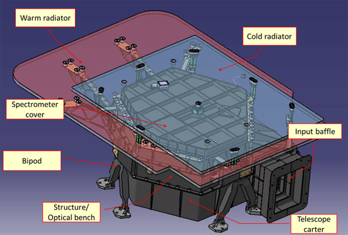
Optical head external view with the two (“warm” and “cold”) radiators (Sect. 4.4.1) (here transparent)
-
the carter telescope which encloses the lower side of the optical bench offering protection to the elements of the telescope and the scanning mirror,
-
the cooling system that uses a dual stage passive radiators system placed in such a way that during the mission should be oriented towards the cold space (+XSC axis).

The adoption of a passive cooling architecture determined the choice of placing the spectrometer on the upper side of the optical bench. This accommodation allows to minimize the distance between the IR FPA and the radiator, thereby optimizing the efficiency of the cooling system.
The main elements of the spectrometer enclosed in the cold box are visible in Fig. 16A, where the radiators and the spectrometer cover have been removed. The lower side of the optical bench is depicted in Fig. 16B that shows the TMA telescope mirrors, the baffle and the scanning unit enclosed within the carter. The baffle is divided in two parts: the internal section, which is contained inside the optical bench, and the external part that protrudes from the instrument arriving to reconnect to the SLI/MLI fixed in front of the radiator. Both parts are realized in black anodized aluminum. The baffle has been designed considering several constraints such as to observe the maximum FOV along the XS/C direction (± 1.7°), to allow the maximum motion compensation angle along the YS/C direction to be reached by the scanning mirror (± 4°), to allow and optimize the housing of the ICU in one of its lateral sides so as to have a minimum mechanical scanning angle of + 8.5° to point towards it and to have a maximum length to avoid vignetting from the first folding mirror of the TMA telescope (FM1). The baffle is also designed to shield the Sun light within an angle > 22° along the X direction and >33° in the Y axis on the side of ICU lamp and >16° in the opposite side.

(A) View of the optical bench and the spectrometer elements inside the cold box. (B) View of the optical bench and the telescope elements inside the carter
The optical bench, whose dimensions are 605 × 520 mm, supports all the optical elements of the system and keeps them properly positioned. In order to minimize its mass and improve the structure dimensional stability, the optical bench is made of stabilized aluminum (Al 6061) black anodized (for thermal purpose). Although not necessary for structural reasons, specific areas of the optical bench have been thickened in order to provide shielding against radiation.
The main structure is supported by three bipods connecting the instrument to the JUICE panel. This bipod arrangement ensures that the direction of minimal flexural stiffness of each bipod is directed toward a common point located in the proximity of the center of mass of the instrument. The thermal elongation of the optical bench is thus compensated by the bipod transversal flexibility minimizing the induced stress in the optical bench. The bipods are essential elements for the structural and thermal performance of the instrument, hence their design has been defined after a trade-off among different solutions. This analysis considered the two opposite requirements of high mechanical stiffness and resistance vs a high thermal insulation. A compromise solution that couples carbon fiber honeycomb legs with titanium terminals has been recognized as optimal, as sketched in Fig. 17.

(left panel) CFRP/titanium bipod configuration. (right panel) Detail of the bipod leg construction
4.1.5 Internal Calibration Unit
The ICU is housed in the telescope’s entrance baffle and is designed to perform calibration tests during the entire operative life of the instrument allowing to evaluate the potential time evolution of instrumental characteristics. Specifically, it will enable to 1) identify defective and out of linearity pixels, 2) check the spectral calibration, as well as 3) the flat-field radiometry and 4) the radiometric and linearity response. Two different calibrated sources, one optimized for the VISNIR channel (incandescent lamp) and one for the IR channel (infrared emitter) are used to illuminate a diffusive element. Each source is equipped with lenses to properly shape the beam. In Fig. 18A is reported a cross-section of the baffle where the lamps and the diffusive element of the ICU are visible, while a lateral view of the calibration unit simulates the light beams coming from the two radiation sources (Fig. 18B). By rotating the scanning mirror by 8.5° towards the ICU optical axis angle it is possible to match the telescope and ICU pupil so as to illuminate the full spectrometer’s slit by the ICU beam.

(A) Calibration unit elements inside the baffle. (B) Section of the baffle with sources light beams
A transmission filter (Didymium for the VISNIR channel and Polystyrene for the IR channel) is placed at the exit of each illuminator to introduce reference absorption features on the ICU light beam. These features can be used to compare the instrumental spectral response with that acquired with the same filters during on-ground laboratory calibration. A comparison of the ICU measurements acquired during the calibration campaign (Sect. 6.1) with laboratory spectra of the ICU source is show in Sect. 6.5.
4.2 Main Electronics Unit
4.2.1 General Description
The electrical architecture is based on a single electronics box, called the ME unit composed of several boards (Fig. 19). The ME unit design is based upon the modular stacking electronics system developed for the SIMBIO-SYS (Cremonese et al. 2020) and JIRAM instruments (Adriani et al. 2017a). It features all the control/command functionalities and powers off the different OH subsystems thanks to several dedicated electronic modules. Specifically, it ensures the communication with/from the JUICE OBC (On-Board Computer), provides regulated secondary power to MAJIS from the unregulated 28-32 V power from JUICE, processes commands from JUICE, controls the MAJIS subsystems, and acquires and formats MAJIS science and housekeeping data then sent to the S/C solid-state mass memory. Below are listed the different elements of the ME (Fig. 19):

Simplified ME block diagram. The ME box is in orange, the OH box in blue. See text for acronyms. Radiator #1 (resp. #2) is the warm (resp. cold) radiator (Sect. 4.4.1)
- Two Proximity Electronics (PE) boards, each one embedding a field-programmable-gate-array (FPGA) that ensures several functionalities for a given channel (VISNIR PE and IR PE). They receive commands from the DPU by means of SpaceWire (SpW) and drive the FPE (Sect. 4.2.2) to acquire science data, perform some preprocessing and eventually send a despiked PE-frame to the DPU via SpW.
- The Auxiliary Board (AUX board) is dedicated to control and to command the auxiliary sub-units inside the optical head: scan unit, shutter and internal calibration sources (Sect. 4.2.2). The AUX board is in interface with the DPU by means of SpW.
- Two Digital Processing unit (DPU), one nominal DPU-N and one cold redundancy DPU-R respectively (Sect. 4.2.2). Each DPU is divided into two elements: 1) a Compression Unit (CU) per channel (VISNIR and IR) for the data transmitted by the relevant PE. Each CU includes a LEON3 processor, a SpW IF and a memory buffer; 2) a Command and Process Control Unit (CPCU) based on a LEON3 processor that manages the SpW interface to the S/C: reception and execution of telecommands, powering on and off of specific PE and AUX units, synchronization with the On-Board Time (OBT), formatting and transmission of telemetry packets (science data and housekeeping) to the S/C. The redundant DPU is identical to the nominal one.
- The PCDU is in charge of the Power Conversion and Distribution to all the sub units of the ME box (Sect. 4.2.2). As the DPU, the PCDU is in cold redundancy. It embeds ElectroMagnetic Interference (EMI) input filters for common mode and differential mode, Voltage and Current protection at primary interface, four independent DC/DC converters (one for each board, namely DPU, AUX, IR PE, VISNIR PE), galvanically insulated I/F to switch On/Off each channel (AUX, IR, VISNIR) by the operating DPU (Nominal or Redundant), EMI output filters on the secondary voltages, O-Ring functions to provide secondary voltages to each non-redounded channel (PE IR, PE VISNIR, AUX).
- The internal SpW and Power flexes that links the different boards together.
- The high-speed data links and power/telecommand lines that connect the ME to the JUICE bus.
4.2.2 Main Electronics Functional Configuration
Except for the front-end electronics of the detectors, the electronic boards are in a dedicated self-standing box. Their detailed functionalities are detailed in the following subsections.
PCDU Board
The PCDU is equipped with power line input filters, DC/DC converters and output EMI filters to provide the needed secondary voltages to other ME modules (digital 3.3 V and analog 10.5 V for the DPU; digital 3.3 V and analog 6 V for the IR and VISNIR PE’s, analog 3.8 V and analog 5.8 V for the FPE’s; digital 3.3 V, analog ±12 V, analog 5 V and analog 8 V for the AUX). The PCDU module manages the current thanks to EMI input filters for both common mode and differential mode. The voltage and current protection at primary interface use reverse polarity protection, inrush limiter, under-voltage lock-out and over-voltage protection. The two fully independent converter boards (Nominal and Redundant) have each four independent DC/DC converters based on the half-bridge technology for the DPU (Main or Redundant), AUX Electronics, IR PE and VISNIR PE. A galvanically insulated interface permits to switch ON or OFF independently the IR PE, VISNIR PE and AUX electronics DC/DC converters by the operating DPU (nominal or redundant). EMI output filters are present on the secondary voltages. Additionally, ORing function with diodes and MOSFET transitors supply the secondary voltages to the non-redounded modules IR PE, VISNIR PE and AUX Electronics regardless of which primary power line is switched ON and thus which DC/DC converter is running. The PCDU also conditions the analog housekeeping that are digitalized on the DPU board (primary currents for each DC/DC converter and one PCDU temperature sensor).
DPU Board
The DPU is the centerpiece of the ME. Its three main modules are a) the CPCU that ensures the Control/Command (TC/TM) and the ME Housekeeping functions with an embedded SpW interface for the TC/TM link with the JUICE OBC and b) two CUs for the science data processing of the two channels with a SpW interface for the communication with the corresponding PE. The DPU has multiple functionalities. It controls the two detectors via high level commands to be sent to the related PE through the SpW communication link, acquires the Housekeeping (HK) data and processed frames (CDS and line corrected, despiked, dark subtracted,…) from PE, performs some additional processing on these frames (spatial and spectral binning, spectral editing, PE-frame binning) leading to the generation of the CU-frames, performs scientific data compression, produces and formats the scientific data for the browse mode, manages the synchronization with the OnBoard Time (OBT), controls the auxiliary units of the optical head via high level commands to be sent to the dedicated AUX board, controls the power up and down of AUX, IR PE, VISNIR PE boards via control signals sent to the PCDU, acquires and digitalizes analog housekeeping of both PCDU and DPU, receives command and send science/housekeeping data through the SpW communication link from/to the JUICE.
The main functions ensured by the CPCU consist of TC reception, decoding and execution from the JUICE OBC, telemetry (HK TM and Native Science Data Packets) encoding, formatting, and transmission to the JUICE Solid State Mass Memory (SSMM) and the instrument observation mode decoding and monitoring. The CPCU handles TC and TM interfaces with the S/C. It is responsible for switching on the two sets of units involved in the acquisition (one for the VISNIR channel, one for the IR channel) and the AUX board which controls OH functionalities (scanner, shutter, ICU light sources). It is controlled by a GR-712 Sparc processor (running at 50 MHz), which was proposed as a “common DPU” by the JUICE project to the instrument teams.
The two CUs are dedicated to the IR and VISNIR channels data processing on each DPU board (nominal and redundant). The main tasks of each compression unit are to handle the data flow from its IFE (Instrument Font-End) and to generate compressed data packets thanks to a GR712 LEON3 processor running at 60 MHz (see Sect. 5.4.3). The 60 MHz clock frequency was selected for the CU to maintain adequate work load margins with the largest CU frame format (640 × 400) and shortest CU-frame repetition rate (500 ms) when data compression is performed, which is nominal for science observations (see Sect. 5.4).
PE IR and PE VISNIR Boards
The 2 PE modules, one for each observation channel IR and VISNIR, perform the following functions: EMI filtering of secondary power supply voltages to the FPA, coming from PCDU; reception of the commands from DPU through the SpW communication link, management of the power up and down of the FPE and FPA, control of the FPE and FPA according to the commands received from DPU, acquisition of the digitized frames from the FPE, data preprocessing, handlings and acquisition of the analog housekeeping (voltages and temperatures of FPA, FPE and PE), sending of scientific and housekeeping data to the DPU via the SpW link.
AUX Board
The architecture of the AUX module is based on an FPGA having the control and supervision of all main functions of the unit EMI filtering on secondary power supply voltages coming from the PCDU, communication with DPU via SpW link, scan mirror mechanism control and monitoring, Shutter control and monitoring, calibration sources biasing and monitoring, temperature acquisition and monitoring, sending of housekeeping to the DPU via SpW link such as scanner position, shutter state, and OH temperatures.
4.2.3 MAJIS ME Redundancies
Cold redundancy is implemented for the PCDU, the DPU and the SpW link in order to improve the safety and reliability of the MAJIS instrument. Either the nominal or the redundant set of units is selected by TC (no cross-redundancy capability). For this purpose, the primary and redundant 28 V power lines from JUICE are kept fully independent and isolated from each other. Specifically, the JUICE primary (resp. redundant) 28 V is connected to the nominal (resp. redundant) converter board through its dedicated common mode EMI filter and then to each nominal (resp. redundant) DC/DC converter through dedicated differential mode EMI filters. The ME can receive TC and send TM using a primary or redundant SpW link. The nominal or redundant PCDU delivers the secondary voltages to sub-systems that have no redundancy (VIS/NIR PE board, IR PE board and AUX board).
4.2.4 SpaceWire
The MAJIS ME uses SpW links at different levels to connect the units and subunit together. The data rate of each direction of each link is an optimized ratio between bandwidth and power consumption (Table 12).
4.2.5 Mechanical Accommodation
The mechanical layout of the ME is presented on Fig. 20. The different electronic boards of the ME are stacked within an aluminum alloy structure ensuring housing, heat dissipation, radiation hardness and EMC. The box is placed in the JUICE vault for radiation mitigation purpose. Additional spot shielding was required for some electronic components that require a radiation dose lower than 50 Krad. The box is composed of five belts (including mechanical frame and PCB), stacked together (top to bottom):
-
PCDU belt with the two PCDU boards (nominal and redundant) and the ORing board
-
AUX belt with AUX board
-
DPU belt with the two DPU boards (nominal and redundant)
-
PE IR belt with the IR PE board
-
PE VISNIR belt with the IR PE board

Scheme showing the different electronics boards within their housing. See text for acronyms
In addition, there are 11 internal flexible harnesses that connect the PCB between them for power and SpW, one JUICE bonding stud IF and two DPU JTAG interfaces for firmware updates (1 debug connector for each DPU).
4.3 Harnesses
MAJIS is constituted of two separated units (OH and ME) that are electrically connected with each other (Fig. 21). Specifically, two harnesses dedicated to the HK and the power connect the AUX board to the feed and control the auxiliary units inside the OH. Two harnesses for the digital signal and low-level analog power lines go from the VISNIR PE (resp. IR PE) to the VISNIR FPE (resp. IR FPE) inside the OH. The ME also communicates with the S/C and returns the acquired data through external harnesses. The monitoring of the survival and anticontamination heaters and thermal sensors (Sects. 3.2 and 4.4) that are located near the sensitive electronics and detectors inside the OH is also performed and controlled by specific harnesses. These thermal harnesses would be a very efficient path for generating conducted noise from the platform through conducted emissions of the JUICE PCDU as well as impact the thermal behavior of the cryogenic FPU’s. To filter the conducted noises, torus has been inserted on the power and sensing lines inside the backshells of connectors plugs on the OH panel.

Detailed electrical interfaces between the MAJIS OH and ME units and JUICE
4.4 Thermal Architecture
4.4.1 Design
The thermal design is driven by the nominal operative temperature limits of the IR and VISNIR detectors. These design-based limits are respectively about 70 ÷ 90 K with ± 0.5 K of stability for the IR FPA, and 120 ÷ 140 K for the VISNIR one (Table 13). The cooler the better for the achievement of the scientific objectives, the higher values constitute a threshold beyond which the performances of the instrument become marginal w.r.t. some of these goals. To reach and maintain these operative temperatures, two radiators are necessary to dissipate thermal loads. The minimization of the thermal exchanges of the instrument structure was also critical. In this context, the bipods play a key role since they provide thermal connection between the instrument and the JUICE optical bench, while effective thermal insulation from the S/C is required through suitable external coating and the interposition of MLI.
The OH is externally mounted and the thermal control is performed independently from the S/C as required. The selected configuration was the use of two passive radiators for autonomous cooling of the optical bench and the detectors (Fig. 15). The so-called “warm” radiator (980 × 765 mm2) is thus in charge of cooling the optical head and the VISNIR detector, while the smaller “cold” radiator (690 × 600 mm2) is thermally conducted just to the IR FPA through a thermal strap and in charge of cooling it down to the required temperature indicated above, driven by the dark current (Sect. 4.1.3). The “warm” radiator that surrounds the cold one acts as a shielding element against external sources of heat. Both external surfaces of the radiators are covered by a white electrically conductive paint in order to increase the heat flux exchanged with the deep space (along the +XSC axis). The radiators are made up with an aluminum sandwich panel, with several anchor points to the structure of the instrument, so as to reach the required structural eigenfrequency and to mitigate the deformations due to the launch vibration. The “warm” radiator needs to be supported on the –ZSC side with cantilevered brackets connected to the vertical wall of the cover. Such brackets have also the function of conducting the heat from the cover towards the radiator ensuring in this way a high thermal conductance even for the outermost parts of the radiator. Since the cold radiator is devoted to the cooling of the IR detector, its operating temperature is much less than that of the cover, and its fastening hardware must guarantee high thermal insulation. To this purpose, fiberglass thermal insulating blades screwed to the supports have been adopted. The blades are oriented to obtain lesser stiffness in the direction in which the different thermal expansions occur between the radiator and the cover to minimize the thermo-elastic loads. The large size and mass of the cold radiator require an additional fixing point in the central position, in order to avoid excessive lateral vibration due to the blades bending. A rigid fiberglass frame connects the center of the radiator to the cover. It supports the lateral loads and limits the flexural deflection of the radiator.
The temperature differences that are present between the radiators and the other parts of the instrument and the environment require also a careful shielding to the radiated heat; as a consequence, the rear surface of both the radiators and all the other surfaces are protected by MLI. The scheme showing the MLI configuration is reported in Fig. 22.

MLI schematic arrangement
The reduction of heat flows from the bipods is particularly complex due to the high temperature difference between the instrument and the JUICE panel. The structure of the instrument has to be maintained at about 130 K while the mounting interface can oscillate between −30 °C and + 20 °C leading to a maximum temperature difference of 163 K. In order to provide the requested thermal insulation, the use of solid titanium bipod was no longer possible and a configuration based on thermal insulating Carbon-fiber-reinforced polymers (CFRP) composite connecting titanium head and feet has been adopted. The bipod legs are constituted by carbon fiber skins molded into a tubular shape by a foam insert. Through holes are machined in CFRP of the leg edges and two opposite titanium bushings are fitted and glued in the hole in suitable position to meet the corresponding hole machined on the titanium fitting wings. The junction between legs and fittings is made with the insertion of a titanium calibrated special pin. The pin is drilled and threaded in order to be locked by an M4 screw which presses the fitting wings against the bushings. This type of connection provides high strength and stiffness to the junction between the legs and the head and the feet of the bipod, while the transversal flexibility of the assembly is provided by the reduced thickness of the leg ends. The conductance of the bipods has been calculated by analysis, then measured with a very good agreement between the analysis and measurement.
4.4.2 Expected in-Flight Performances and in-Flight Monitoring
The in-flight performances are extrapolated, through our thermal model, from the results of the thermal tests performed on the S/C with the MAJIS dedicated unit (STM) (Table 15). A second test campaign, performed with the MAJIS PFM, in a different vacuum environment was in line with the first measurements and the thermal performances of the instrument that are summarized in Table 13.
The model predictions show that the instrument will stay within its Non-Op temperature range during the cruise, which is the predicted coldest part of the mission. It also ensures that it will stay in the Op temperature range when orbiting during the Jupiter tour and the Ganymede phase, for all scientific data acquisition periods. For the last mission phase GCO500 where the S/C is at its closest point to another celestial body, we expect that the temperatures of the detectors will be exceeding the target temperature (95.7 K instead of 90 K) which will slightly impact the performances.
In order to monitor the temperatures during the mission, a set of platinum resistant temperature detector’s sensors acquired by the S/C have been implemented in the instrument, at the most relevant locations: IR FPA, both FPE’s, and OH structure. These sensors are acquired via the JUICE main electronics, and can thus also be read during the Non-OP phases (MAJIS OFF). The acquisition frequency has been optimized for the MAJIS needs. They will also be used for the survival heating control of the FPE’s and for the anticontamination control of the IR FPA and OH structure. The Non-Op temperatures monitored during the NECP are reported in Table 13. Even if additional thermal simulation is required for this specific case (close to the Sun and with a particular S/C attitude), they are at first glance in line with the thermal expectations.
When the instrument is operating, additional internal housekeeping sensors, located in the scan mechanism and in the detection chain (both FPA’s and FPE’s) are acquired by the MAJIS Main Electronic Unit (both FPA’s and FPE’s). The overshields of the thermal sensor and heater harnesses (anticontamination line) are made of stainless steel in order to minimize the thermal leaks between the coldest part of the instrument (IR FPA) and the hotter sub-units of the OH. The overshield is overwrapped with aluminized mylar for cleanliness purpose.
4.5 Instrument Budget
Key system parameters are given in Table 14.
5 OnBoard Software and Data Processing
The core onboard software on MAJIS include several electronic units (Sect. 4.2) and core functions that feature autonomy, data processing and S/C interface that are described in this section.
5.1 MAJIS Architecture for Process Control and Data Processing
A MAJIS operational sequence from switch-on to switch-off consists in preparing then acquiring one or several sets of data frames each corresponding to an observation with specific operational parameters (in particular the spatial and spectral dimension of each frame and the repetition time between frames, see Sect. 7.1). The functional architecture of MAJIS for achieving this objective is presented in Fig. 19.
The CPCU oversees all MAJIS activities from switch-on to switch-off (Sect. 4.2.2). The CPCU software is written in C following coding standards for flight software. It configures all units involved in the acquisition with the parameters relevant for the next observation before initiating the acquisition of data frames. If only one channel is used in the operational sequence, it is possible to switch on only the units (CU, PE, FPE and FPA) relevant to this channel so as to minimize power.
The CU software, which is the same for both channels, is written in C following coding standards for flight software. It is loaded by the CPU from the MRAM after switching-on the CU unit. A set of configuration parameters sent by the CPCU before each observation defines how to process PE-frames sent by the PE into a CU-frame, then how to format series of 1 to 8 CU frames into science data to be sent to the SSMM through the CPCU. The CU parameters have to be consistent with those of the corresponding PE as a specific number of PE-frames with the required dimensions have to be received by the CU before it can generate CU-frames. Each CU has also a retransmission role for messages between the CPCU and the PE of the same channel.
Each of the two PE’s is a non-reprogrammable FPGA. It is configured by the CPCU before each observation by sending a set of parameters defining how to process the FPA-frames sent by the FPE into a PE-frame sent to the corresponding CU. The PE parameters have to be consistent with those of the corresponding FPE’s as a specific number of FPA-frames with the required dimensions and data format (12 bits or 16 bits/pixel) have to be received by the PE so that it is able to generate a PE-frame. The PE has also a retransmission role for messages from the CU to the FPE of the same channel.
The AUX board is also equipped with a non-reprogrammable FPGA. It is configured by the CPCU by sending specific commands before and after the observation, in particular the scanner start position, velocity and acceleration (the scanner must be commanded to the zero position even if not used so as to remain stable at boresight). The CPCU sends to the AUX board a “start scan” command together with the first data frame request and a “return to 0” command after the observation if scanner motion is required. “Shutter close” then “shutter open” commands are sent by the CPCU to the AUX board whenever a dark current acquisition is required. Internal calibration sources are switched on then off by the CPCU during internal calibration sequences (typically once per month) after setting up the scanner in a direction looking at the ICU diffuse screen beyond the edge of the FOV. Before sending each new frame request, the CPCU sends a request to the AUX board for relevant status data (shutter status, scan position, status of internal calibration sources) so as to include this context information in the science data.
Each of the two FPE’s is a SIDECAR ASIC that acquires frames from the H1RG detector then sends them to the corresponding PE (Sect. 4.1.3). The FPA is switched on together with the FPE. The FPE is programmable with a specific assembly language code (“microcode”). It is configured by the CPCU before each observation by loading one of two microcodes (one for each of two detector read-out speeds, 100 kHz and 1 MHz) including a set of five parameters specific to each observation. Similarly to the two CU’s, the same microcode can be used for either the IR FPU or the VISNIR FPU. A “low power” microcode which resets all internal FPE units is loaded after the initial switch-on and between observations so as to minimize power. This procedure automatically implements a thus named “warm” reboot of the FPE after each observation, which is useful for Fault Detection Isolation Recovery (FDIR) matter.
An overview of the data processing tasks performed by the MAJIS onboard software to generate a CU-frame of a given spectral cube from multiple FPA-frames is shown in Fig. 23. The functionalities of each unit involved in this processing are presented in greater detail in the following sections.

Overview of the data on-board pipeline as a function of the electronic units. The corresponding data products generated at each major step is illustrated. The gray area and the references pixels are masked. See text for acronyms
5.2 CPCU Software Architecture
As indicated in Sect. 5.1, the CPCU oversees all MAJIs activities when the instrument is ON. After switch-on, it is controlled by a boot software provided by ESA in the framework of the “common DPU” project activities, with a few adjustments specific to MAJIS. The boot software is therefore able to handle all mandatory services required for interfacing with the JUICE system level. At this stage, the instrument is in “standby” mode. In this mode, it is possible to update the content of the MAJIS MRAM which stores two memory images of the software to be loaded in the programmable MAJIS functional units: CPCU Application Software (ASW), CU software (CUSW) and FPE microcodes (“low power”, 100 kHz read-out, 1 MHz read-out). Upon receiving an “ASW load” command, or after a timeout of 30 s, the boot software loads the ASW software from the MRAM then transfers controls to the ASW. This puts MAJIS in a “safe” mode (all subsystems other than the CPCU are off) (Fig. 24).

Sequence of MAJIS modes from switch-on to switch-off. See text for a definition of the modes (“standby”, “safe”, “service” and ‘science”)
The MAJIS ASW design is based on a Time and Space Partitioning (TSP) architecture. At the lower level, an hypervisor (Xtratum provided by Fentiss) ensures the segregation of the execution of the different software functionalities enclosed into “partitions”. On top of the hypervisor, a generic payload software called LVCUGEN, designed and provided by CNES, implements the basic and recurrent functions used by flight SW and is extended by several partitions:
-
an “Input/Output” partition (IOS partition) used to access the SpaceWire bus developed by the ATOS under a CNES contract with specifications updated by IAS,
-
a Command-Control partition (CCSW partition) implementing the instrument operability also developed by the ATOS under a CNES contract with specifications updated by IAS,
-
a Mission partition (MSW partition) specific to MAJIS which is in charge of the sequence of actions required for performing the series of MAJIS science observations from switch-on to switch-off on the basis of the sequence of MAJIS private TC’s in the timeline.
5.3 MAJIS Operational Sequences and Modes Controlled by the MSW
The activities required for science data acquisition, formatting and transmission to the outgoing data front-end modules are all controlled by the MSW. Once in “safe” mode, a first set of commands triggers the switch-on by the MSW of the two sets of sub-units which are required for acquisitions (CU, PE, FPE and FPA which are switched on together). Operating with both channels is nominal. For very specific operations, or for degraded operations if one of the channels is not working anymore, it is possible to switch-on only one acquisition chain.
The FPGA-based PE’s is immediately operational. Once the CU’s are switched-on, the MSW triggers the loading of the CUSW from the selected image in the MRAM. At this stage, the “low power” microcode is loaded in the FPE’s so as to minimize power. Once the proper initialization messages have been received from the PE’s and CU’s (not the FPE’s, which are in reset), the MSW transitions into the”service” mode, which is required for MAJIS to accept TC’s triggering science observations (Fig. 24).
A science observation is initiated by a sequence of two TC’s: the “configuration” TC and the “Start Science” TC. Below we describe the functionalities that are triggered by these two TCs and the activities at the end of an observation.
5.3.1 “Configuration” TC Description
The “configuration” TC provides all the parameters required for acquiring the next science data set. The two highest level parameters are the number of MAJIS data frames (“CU-frames” as they are built then formatted by the CU from one or several “PE-frames” coming out of the PE depending on a frame averaging parameter which is specific to each channel) and the repetition time between CU-frames (as the MSW is triggered every 25 ms, it has to be a multiple of 25 ms). There are two options for the number of MAJIS data frames (an unsigned 16 bits number): if lower than 65535, it is considered as such (“fixed number of frames” observation). If equal to 65535, it means that the number of acquisitions is not defined (“segment” observation). In that case, the acquisition of frames will be stopped by a specific “Stop Science” TC in the MAJIS timeline.
When a configuration TC is received, the MSW sends the parameters relevant to each of the switched-on CU’s and PE’s on a “need to know” basis. The main parameters for the CU are the number NPE of the PE-frames which are to be averaged to obtain a CU-frame, the size of the PE-frames (nominally 400 pixels covering the full MAJIS FOV × 508 spectels). Averaging parameters are also sent to the CU: a spatial averaging by 1, 2 or 4 can be applied to the PE-frame on top of the averaging performed by the PE. In the spectral direction, the CU can perform spectral editing (which consists in skipping a spectral range when formatting the data) and spectral averaging on top of that performed by the PE) selected independently for each of up to 16 spectral bands. Data formatting with or without compression is performed by the CU. The 3-D compression scheme is based on the CCSDS 123.0-B-1 lossless compression standard which is implemented on a set of 8 CU-frames (less for the last set if the total number of frames is not a multiple of 8). Lossless compression is implemented after shifting the values by 1 to 8 bits to the right, which reduces the number of bits required for coding each value while increasing the quantization interval, hence the quantization noise. MAJIS data sets can cover large signal variations along the spectrum by a factor of up to 20 for both the VISNIR and IR channels. Therefore, the shift parameter can be set at a different value for each of the CU spectral bands depending on the signal level (which defines the shot noise) as optimum data quality is obtained when the quantization interval does not exceed the noise level. Larger shift settings (hence higher data compression ratios) can be selected on the basis of a trade-off between data quality and data volume.
The PE parameters define how a PE-frame is built. The H1RG detector is read-out with correlated double sampling: a first detector frame is obtained by the FPE by reading out each detector row after resetting it, then a second detector frame is read-out after a time interval which corresponds to the integration time. The FPE only reads-out the 800 detector rows corresponding to the MAJIS FOV (less if a smaller window is requested). Subtracting the “reset” frame from the “read” frame generates the CDS (correlated double sampled) frame that provides the number of electrons collected by each detector pixel (18 μm × 18 μm) during the integration time. This subtraction is performed by the PE so as to obtain a “sub-frame”. At this stage, the 8 reference pixels of each row (4 on each side of the detector) are used so as to provide the 0 level for the 1016 connected detector pixels, so that a full FOV sub-frame is stored in the PE RAM as a 800 rows × 1016 spectral values array. The PE-frame is built from several sub-frames so as to mitigate radiation noise (“de-spiking”) (Langevin et al. 2020). De-spiking is performed by sorting for each detector pixel the N values from each sub-frame from lowest to highest, then averaging the M lowest values. For a given pixel and wavelength, this screens out acquisitions for which the detector pixel has been impacted by a high energy electron, which generates a large number of additional electrons. Splitting the acquisition into sub-acquisitions with short integration times is also required for avoiding saturation with the VIS channel when observing icy moons or Jupiter and with the IR channel when observing Jupiter hot spots.
The PE needs to know the following parameters:
-
the size of detector frames (800 detector rows × 1024 spectral values for a full FOV acquisition),
-
the number N of sub-frames (from 1 to 8),
-
the number M of low values to be averaged for de-spiking,
-
the detector read-out mode as the data comes out either as a 12-bit integer (1 MHz read-out) or a 16-bit integer (100 kHz read-out).
A first stage of averaging is performed by the PE, averaging pairs of successive rows so that 800 rows (pixels) result in 400 MAJIS pixels for the full FOV. Nominal spectral averaging is also by pairs in the spectral direction, but up to 264 spectels in 4 spectral bands can be selected so that they are included in the PE frame without spectral averaging (“oversampling”). As a result, the full FOV PE-frame built by the PE from N × 2 detector frames sent by the FPE (each 800 × 1024 detector pixels in size) has a size ranging from 400 × 508 to 400 × 640 data elements in case of oversampling (see Fig. 23).
The MSW configures each of the two FPE’s by loading into the CPCU RAM the microcode corresponding to the commanded read-out mode for this channel (1 MHz read-out or 100 kHz read-out, it can be different for the VISNIR channel and the IR channel) and overwriting the parameters zone with the FPE command parameters extracted from the configuration TC:
-
number of sub-frames to be acquired,
-
−1st row and number of rows in the selected window; the 1st row parameter can be selected at different values for the VISNIR and IR channels so as to cope with a small shift in position between the two channels,
-
sub-integration time (in ms).
The modified microcode is then loaded to the FPE. If the upload is successful, the FPE is considered by the MSW as ready for accepting frame requests.
The MSW also configures the AUX board by sending three commands extracted from the configuration TC. For what concerns the scan mechanism, MIRROR_position defines the start position of the scanner (Sect. 4.1.2). It is enacted by the AUX board upon reception. Mirror_Speed defines the initial angular speed of the scanner. If set at 0, it means that the scanner will remain at the start position for the whole observation. Mirror_acceleration defines the way Mirror_speed will change over time, which is required for motion compensation on non-circular orbits (satellite flybys, elliptical orbital phases around Ganymede). Both Mirror_speed and Mirror_acceleration will only be enacted when the AUX board receives a “Start scan” command.
5.3.2 “Start Science” TC Task
The “Start Science” TC triggers the start of the observation if (and only if) all required sub-units have been successfully configured. If this is the case, the MSW sets MAJIS into “science” mode (Fig. 24). The first action consists in initiating a “dark before” CU-frame acquisition (if requested by the configuration TC): this requires closing the shutter, acquiring a dark CU-frame then re-opening the shutter (this takes ∼ 300 ms, which is much longer than the time required by the CU for formatting the dark CU-frame). The specific characteristics of dark CU-frame acquisitions will be discussed in Sect. 5.4. Once the “dark before” activity is complete, the MSW sends a “start scan” command to the scanner if a scanner motion is required. When receiving this command, the AUX board will initiate the motion of the scanner according to the Mirror_speed and Mirror_Acceleration it received from the MSW on the basis of the configuration TC. The MSW initiates the high-level cycle for acquiring CU-frames at the time intervals defined by the configuration TC. At the beginning of each CU-frame cycle, the MSW requests from the AUX board the current values of relevant parameters (scanner position, shutter status, status of internal calibration sources) and it sends them to the CU together with other relevant parameters (in particular the detector temperatures) so as to be included in the science data stream (Sect. 5.4).
5.3.3 End of Observation Processing and Output Data Product
End of observation activities are triggered when the required number of CU-frames have been acquired or when a “Stop science” TC is received (“segment” observations). In both cases, the MSW sends a message to the CU’s informing them that the on-going CU-frame cycle is the last one. When formatting of this CU-frame for both channels is complete, the MSW sends a “go to zero” command to the AUX board so as to return the scanner to boresight. If requested by the configuration TC, the MSW then initiates a “dark after” CU frame acquisition if requested by the configuration TC.
There are therefore at least one and at most three CU-frame acquisition sequences during an observation: the “dark before” CU-frame (if requested), the observation CU-frames and the “dark after” CU-frame (if requested). Formatting each of these acquisition sequence by the CU results in a string of “Native Science Data Packets” (NSDP) sent to the CPDU (see Sect. 5.4 and Fig. 23). After formatting the last CU-frame of a frame acquisition sequence (which is also the first CU-frame for “dark before” and “dark after” sequences), the CU sends a “last data packet” message to the CPDU. Reception of the last of the two messages indicates to the MSW that it has received all the NSDP packets corresponding to an acquisition sequence from the two CU’s. Therefore, the reception of the last of the two messages for the last acquisition sequence (observation, or “dark after” if requested) indicates to the MSW that it has received all the NSDP’s corresponding to an observation. As will be discussed in Sect. 5.4, the MSW checks every 25 ms the status of the outgoing buffers of MAJIS data (one for each channel), hence it knows when the last NSDP corresponding to an observation has been successfully transmitted to the SSMM. The MSW then sends two events which close the data files corresponding to an observation in MAJIS dedicated section of the SSMM, one for high priority data and one for low priority data (“browse” and “nominal”, see below and Sect. 5.4).
“Browse” data files (received within a few days through X-band) are used for selecting which of several “nominal” data files corresponding to an observation will be requested for downlink at a later stage through Ka-band (“selective downlink”). The high priority file can be empty if no browse data is requested, which is the case for observations whose downlink is considered mandatory, so that the “nominal” data file will always be flagged for transmission. The MSW then switches the active settings of high priority (HIPRI) and LOPRI NSDP headers to be used by the CU’s so that the next NSDP’s prepared by the CU’s will be sent to an alternate set of two data stores in the SSMM. This flip-flop approach with two sets of data stores in the SSMM used alternatively makes it possible to initiate a new MAJIS observation shortly after the end of the previous observation.
After triggering file closure in the MAJIS data stores, the MSW goes back to service mode, waiting either for the next pair of “configuration” TC followed by a “start science” TC triggering the start of a new observation or a sequence of switch-off TC’s which sets MAJIS back to safe mode, respecting specifications for FPE/FPA switch-off (“graceful shutdown”). Once back in safe mode, MAJIS waits to be switched-off at system level.
5.4 Control Activities and Data Flow in Science Mode
On the basis of the commanding scheme presented in the previous sections, there are three nested cycles triggered by the CPCU during the acquisition of a science CU-frame:
-
the sub-frame acquisition cycle, each sub-frame requiring two detector read-outs, one immediately after reset and the second one integration time later,
-
the PE-frame acquisition cycle, generating a PE-frame from N sub-frames by averaging the lowest values among N for each detector element (18 μm × 18 μm), then applying the selected spatial and spectral averaging scheme,
-
the CU-frame acquisition cycle, generating a CU-frame from NPE PE-frames (frame averaging).
These steps are detailed in Fig. 25 for a CU frame constructed from a single PE frame (no frame averaging), a despiking strategy averaging the lowest 3 values of 5 sub-frames (as example, 10 detector read-outs are here transferred from the FPE to the PE during the PE-frame repetition time) and dark subtraction (nominal for science observations).

Data flow from the FPA to the CU for a full FOV observation (400 MAJIS pixels derived from 800 detector rows) implementing a de-spiking strategy with 5 sub-frames (e.g averaging the 3 lowest values for each data element of the sub-frames that is assumed to be the despiking parameters required for GCO5000)
5.4.1 Sub-Frame Cycle
The sub-frame acquisition cycle is initiated by the FPE after receiving a “PE-frame request” message from the MSW transmitted through the CU and PE. Before transferring the PE-frame request message to the FPE, the PE checks that it has already received the 2xN detector frames required for preparing the previous PE frame (otherwise, it sends back to the MSW an error message indicating that the frame request came in too early). During the sub-frame acquisition cycle, the PE activities are triggered by the reception of detector frames from the FPE. The time FPE takes for acquiring a frame is longer with 100 kHz read-out (529 ms for a full FOV, 800 rows) than with 1 MHz read-out (64 ms for a full FOV). The conversion of the “read” frame cannot be initiated before the end of the conversion of the “reset” frame. Therefore, the minimum integration time for a full FOV is 64 ms with 1 MHz read-out and 529 ms with 100 kHz read-out. For short integration times, the 1 MHz read-out mode is mandatory. The 100 kHz read-out mode has a lower read-out noise than the 1 MHz read-out mode and a lower power consumption (Table 11). Even considering the smaller time fraction available for collecting electrons (Fig. 26), the 100 kHz read-out mode provides improved performances for very low signals (e.g. exospheres, rings) and long integration times.

Chronogram of a sub-frame cycle at 1 MHz (top) and 100 kHz (bottom). Each vertical dashed line defines the request of a read or reset image. The red ramps correspond to the conversion of successive rows for the “reset” image, while the green ramps correspond to the conversion of successive rows for the “read” image. As discussed in Langevin et al. (2022), with 1 MHz read-out, the sequence needs to be initiated by a “drop” read frame (which is not transmitted to the PE) so as to ensure that for a constant signal the first sub-frame is at the same level as the next ones, which is required for the validity of the de-spiking procedure. With 100 kHz, a “drop” sub-frame (reset, then read) is required, and the interval between the read and reset frame must be the same as that between the reset and read frame (integration time tint). The duty cycle for collecting electrons (sum of the tint intervals) is larger than 50% with 1 MHz read-out even considering the drop “read” frame at the beginning of the cycle and the PE processing time (tproc). It is smaller than 50% at 100 khz due to the stiffer penalty incurred for ensuring reliability
The transmission of detector frames from the FPE to the PE is performed on a 12 bits parallel bus at a rate of 10 Mpixels/s for 100 kHz read-out (16 bits ADC conversion by the FPE). With 1 MHz read-out (12 bits ADC conversion by the FPE), only the 12 LSbits of the parallel bus are used and the rate is 20 Mpixel/s. The transmission time is 41 ms for a full FOV (800 rows) with both read-out modes. The chronograms of sub-frame cycles are presented in Fig. 26 for the two conversion rates.
5.4.2 PE-Frame Cycle
The reset image is stored as such in one of the 8 sub-frame buffers in the PE RAM. When each row of the “read” image is received, the PE subtracts the values from the corresponding “reset” row then the average difference for the 8 reference pixels (which provide a 0 reference as these pixels are not connected). The PE divides the result by 2 with 100 kHz read-out and multiplies it by 8 with 1 MHz read-out so as to obtain in both cases a signed integer with a 16-bit dynamic range, which is stored back in the sub-frame buffer. When all N sub-frames (N × 2 detector frames) have been received, the PE prepares the PE-frame by performing first the selected de-spiking procedure (average of the lowest M values out of N for each of the detector pixels contributing to a PE-frame data element) then (2 or 4 depending on whether oversampling or nominal sampling is selected for this wavelength range) which has been defined on the basis of the local radiation flux (much higher for Europa than for Callisto) so that at most 1% of data elements are still impacted after de-spiking (Langevin et al. 2020).
If dark subtraction is requested, which is nominal for science observations, the PE subtracts the corresponding value of the dark frame which is stored in its RAM before sending the result to the CU over a SpW link operating at 40 Mhz (2 Mpixels/s). The dark frame must to be acquired with the same acquisition parameters (first row, number of rows, de-spiking strategy, read-out speed, integration time) and the same oversampling ranges as the observation itself for the dark subtraction to be legitimate. For a full FOV, the dark subtraction processing time ranges from 108 ms (minimum size PE-frame of 400 × 508, number of sub-frames < 4) to 250 ms (maximum size PE frame of 400 × 640, number of sub-frames = 8). A PE-frame must be completed before the 1st row corresponding to the next PE-frame is received by the PE leading to additional constraints on the minimal interval between PE-frame request.
The dark PE-frame is updated by a specific procedure in which the MSW sends 9 PE-frame requests to the FPE which are flagged as dark PE-frame requests for the PE. In that case, the FPE produces and the PE processes each series of sub-frames with exactly the same procedure as for observation PE-frames (de-spiking, then spatial averaging, oversampling or nominal spectral averaging) except that there is no dark subtraction (the shutter is closed, but the FPE and PE do not have this information). The PE adds the outcome for each data element to a “total” buffer and it compares it with the previous highest value for this data element stored in a “max” buffer so as to update it if higher. After processing the 9th dark frame, the PE subtracts the “max” buffer from the “total” buffer before dividing by 8, stores the result in the “dark” RAM buffer and sends it only then (after 9 PE-frame requests) to the CU as the “dark PE-frame”. This provides an average of the 8 lowest de-spiked values out of 9. If the configuration TC does not request averaging by the CU, the de-spiking parameters have been selected so that at most 1% of data elements in a PE-frame are impacted after de-spiking for each of the contributing 9 PE-frame acquisitions. With this procedure, at most 0.34% of the data elements in the dark PE-frame remain impacted as this requires that at least 2 of the 9 values corresponding to the same data element in the PE-frames are impacted.
5.4.3 CU-Frame Cycle
Frame-Binning
The activities of the CU during a CU-frame cycle are controlled by the end of the reception of PE-frames from the PE similarly to the FPE-PE relationship during a PE-frame acquisition. The CU works on two stacks of 8 CU-frames, one for storing incoming PE-frames and the other for formatting the previously received PE-frames as CU-frames, the two processes running in parallel. The procedure implemented by the CU is presented when compression is implemented as it is nominal for all MAJIS science acquisitions. Each data element of a PE-frame corresponds to 16 bits signed integer so that 2 data elements can be stored at a 32-bit address. If the CU-frame is built from a single PE-frame (parameter NPE = 1, no frame averaging), the PE-frame is stored as such in the next available slot of the acquisition stack. If frame averaging is requested (NPE ≠ 1), the first PE-frame is stored in a 32-bits buffer and the following ones are added to it. After the last PE-frame has been received, each data element in the 32- bits buffer is divided by NPE, providing an average of the values for the NPE contributing PE-frames which it is stored in the next available slot of the acquisition stack.
As shown on Fig. 27 for an observation during the GCO5000, the way a CU-frame is built can be quite different for the VISNIR and IR channel. A de-spiking strategy averaging 3 sub-frames out of 5 (as presented in Fig. 25) is adequate for both channels in the Ganymede radiation environment. The dwell time is very long (7.8 s), so that the 100 kHz read-out mode can be implemented for the IR channel with a 650 ms integration time. However, the VISNIR channel would saturate, hence a much shorter integration time of 99 ms is selected (this requires implementing the 1 MHz read-out mode), with frame averaging of 8 PE-frames during the 7.8 s long CU-frame cycle.

CU-frame cycle for a GCO5000 observation. The long CU-frame repetition time (7.8 s) is allocated to a single PE-frame for the IR channel, while 8 successive PE-frame requests are issued to the VISNIR channel at intervals of 975 ms (frame averaging by 8). The drop frame explains the additional one frame to be considered for the calculation of the CU-frame repetition time (Fig. 26). A request for HK (mirror position, shutter status, sources) is issued by the MSW to the AUX board immediately before sending the first PE-frame request of the CU-frame cycle (in that case, the scanner is fixed at boresight). As soon as the AUX board has sent back this information, the MSW sends it to the CU’s together with the on-board time of the 1st PE-frame request and other relevant HK values
Spatial Averaging, Spectral Editing/Averaging
These tasks are defined by the “configuration” TC (Sect. 5.3.1) They are performed on sets of 8 successive CU-frames (called “bricks”) which are processed together. The first step when processing a brick consists in preparing a first data packet that contains, for each of the 8 CU-frames formatted in the brick, 1) the on-board time of the first PE-frame request and 2) the relevant HK values that are sent to the CU by the MSW after initiating a new CU-frame cycle. After that, the CU extracts the nominal data stream from the brick by “sub-bricks”, with a size of e.g. 50 pixels × 64 spectels × 8 CU-frames for full FOV frames (400 pixels) with the maximum number of spectral elements (640). Each row of 8 sub-bricks corresponds to one of the CU spectral ranges (up to 15) as defined in the “configuration” TC, with a spatial averaging parameter that is common to both channels and all spectral bands, while a spectral editing and a spectral averaging and a compression parameter (shift) are specific to each CU spectral band (Sect. 5.3.1)
If the CU spectral band is flagged as edited, the CU does not format it (i.e. the spectral band is discarded). For non-edited spectral bands, the CU can implement spectral averaging by 1, 2 or 4. Spectral averaging by the CU is inhibited for spectral ranges for which the PE has been instructed to implement oversampling (i.e. not implementing the spectral averaging by 2 which is nominal). The number of detector spectels contributing to a MAJIS data element is therefore 1 (PE oversampling), 2 (PE nominal averaging, no CU spectral averaging), 4 (CU spectral averaging by 2) or 8 (CU spectral averaging by 4). The size of the rectangle of 18 μm × 18 μm detector elements which are averaged into a MAJIS data element is presented in Fig. 28 as a function of the spatial averaging parameter and the spectral averaging parameter for a given spectral band.

Size of the rectangle of detector elements (18 × 18 μm) contributing to a MAJIS data element as a function of the averaging parameters. The spatial dimension is in green, the spectral dimension is in red. The nominal size is 2 × 2. The selection of the size will be adapted according to the science case. Up to 64 18 × 18 μm data elements are averaged so as to obtain a data element of a PE frame, more if frame averaging is implemented. This must be considered when defining the de-spiking strategy as the result is unreliable if one of the contributing values is still impacted
Browse Data Formatting
If browse data is requested by the configuration TC, a first row of sub-bricks is generated by extracting from the stack of PE-frames, which always cover the full wavelength range of the channel, up to 32 data elements corresponding to wavelengths defined by a browse table selected by the configuration TC out of 31 possible browse tables (0 meaning “no browse”) stored in the CPCU MRAM. There is one set of 31 browse tables for each channel, each defined for a specific target (icy moons, Jupiter, exospheres...). The browse table is loaded by the CPCU in the CU when configuring it for each observation. Additional spatial averaging can be applied to the browse row on top of that already applied to nominal data so as to reduce the browse data volume (a data volume lower than 5% of that of the nominal data set is targeted). The browse NSDP’s are tagged with the “high priority” logical address for storage in the SSMM.
Dark Frame Processing
When receiving from the PE a “dark” PE-frame, the CU prepares a “dark” CU-frame by applying the same spatial averaging, spectral editing and spectral averaging parameters as for observation CU-frames. It also uses the same spatial and spectral division into sub-bricks for formatting it as for observation CU-frames. However, each “dark” CU-frame is formatted as a standalone without compression by filling up 32-bits words by 16-bit values for each data element when preparing the NSDP’s. A “browse” dark CU-frame is prepared if browse data is requested by using the same browse table as for observation CU-frames, and it is also formatted without compression with the high priority tag. For both nominal data and browse data, this makes it possible to recover the CU-frame values before dark subtraction in case the temperature of the detector (which is available for each CU-frame in the first NSDP of a brick) has significantly changed during the observation. One can then interpolate values from dark frames acquired before and after the observation on the basis of the detector temperature so as to subtract the dark level which is relevant for each CU-frame.
Compression and NSDP Formatting
Formatting with compression is performed on a set of “bricks”, each consisting of 8 successive CU-frames which are processed together (3-D compression scheme). The number of CU-frames can be smaller for the last brick if the total number of CU-frames is not a multiple of 8. The CU compresses the brick by sub-bricks (see Sect. 5.4.3). As an example, if no spatial or spectral averaging by the CU is requested in the configuration TC, there are 10 rows of sub-bricks of 50 pixels × 64 spectels × 8 CU-frames if maximum oversampling is implemented for full FOV frames (400 pixels × 640 spectels). The shift parameter which defines the level of compression is also defined for each CU spectral band of the VISNIR and IR channels by the configuration TC. The target for MAJIS data compression is ∼ 5 bits/data (starting with 16 bits/data) when averaged over the full spectral range. Note that the compression level of any browse can be set higher than for nominal data.
Reversible compression of each sub-brick results in a string of 32-bits words which are formatted as NSDP each accommodating up to 1026 32-bits words of compressed data. The nominal NSDP is tagged with the logical address LOPRI for storage in the SSMM. NSDP are also tagged with the row and rank in the row of the sub-brick being processed, so that the MSW can detect upon reception the start and end of a string of NSDP’s corresponding to a sub-brick. When the CU receives the “last CU-frame” message from the CPCU/MSW, it formats the last set of CU-frames as a brick of 1 to 8 CU-frames, and after the last sub-brick of the nominal data stream has been formatted it puts a “last NSDP” message in the output stack so as to inform the MSW that formatting of the on-going CU-frame acquisition cycle is over.
Transfer to the SSMM
The CPCU activities linked to the MAJIS data flow consist in providing to each CU the relevant HK values for each CU-frames and in making sure that all generated NSDP’s are successfully transmitted to the JUICE SSMM. The NSDP transfer process from the CU to the SSMM is presented in Fig. 29. NSDP’s are received in one of two input stacks, one for each CU. The NSDP stack is large enough to guarantee optimum usage of the maximum useful data rate of 42 Mbits/s (64 × 20 NSDP’s can be transferred in 1 s, each with 1026 32-bits words of compressed data). The margins for science data transmission are more than adequate as it is nominally compressed (target: 5 bits/data) so that the maximum expected data rate is ∼ 10 Mbits/s. The maximum transmission rate is also adequate (with smaller margins) in the few cases when uncompressed data is sent when performing an internal calibration.

Transfer of NSDP’s from their build-up by the VISNIR and IR CU’s to the MAJIS dedicated data stores in the SSMM. The output stacks (TX) and input stacks (RX) all provide 64 slots, as well as the internal buffer used by the two IOS partitions. The large NSDP stack managed by the MSW partition guarantees optimal usage of the bandpass and it mitigates the impact of short duration interruptions of the SpW link to the SSMM. For this observation, NSDP are stored in the MAJ1 (high priority) and MAJ3 (low priority) data stores of the SSMM. For the next observation, they will be stored in the alternate set of data stores, MAJ2 and MAJ4
A sequence of observations between a MAJIS switch-on and a MAJIS switch-off results in successive sets of two data files, a “nominal” data file in a LOPRI MAJIS data store of the SSMM and a “browse” data file in a HIPRI data store. If no “browse” data is requested, the “browse” data file is still created, but it is empty after closure. The two sets of data stores (MAJ1 and MAJ2 for high priority, MAJ3 and MAJ4 for low priority) are used in alternance for each observation (MAJ1 and MAJ3, then MAJ3 and MAJ4, MAJ1 and MAJ3, and so on). All MAJIS browse data files (including the empty ones) are transferred within a few days to ground by X-band. In compliance with the selective downlink scheme selected for JUICE, the MAJIS team will flag for transmission by Ka-band all nominal data files for which the browse data file is empty, and a subset of the nominal data files with associated browse data on the basis of its evaluation of the browse data set.
6 Testing, Calibration, and Performance
6.1 Performed Measurements
The validation of the performances and functionalities is in line with the verification methods defined for other space-borne imaging spectrometers, including OMEGA (Observatoire pour la Minéralogie, l’Eau, les Glaces et l’Activité) on Mars Express (Bonello et al. 2004), VIRTIS (Visible and Infrared Thermal Imaging Spectrometer) on Rosetta (Ammannito et al. 2006), JIRAM on Juno (Adriani et al. 2017a), and SIMBIO-SYS/VIHI on BepiColombo (Filacchione et al. 2017). Specifically, the functional and performance verification strategy combined simulations and measurements from subsystems to the integrated system level during assembly and integration on the S/C according to five steps:
1. Calibrations and tests at the components level (focal planes, scan mirror mechanism...);
2. Calibration and tests at the subsystem level (OH, ME as separate units);
3. End-to-end functional tests at instrument integrated level;
4. Calibration and tests at instrument integrated level;
5. Assembly, Integration and Test/Verification (AIV/AIT) activities during MAJIS integration onboard the S/C.
The major test campaigns are listed in Table 15.
After launch, in-flight check-outs are performed on a routine basis to monitor the health and performance of the instrument (Sects. 6.6 and 7.2).
6.1.1 Calibrations and Tests at Component Level
Instrument components such FPAs, spectrometer, telescope, scanning mirror mechanism, shutter, internal calibration sources were independently tested prior to their integration (Table 15). Critical components were the MAJIS VISNIR and IR FPUs for which the following measurements at different temperatures and/or wavelengths were addressed (Carter et al. 2002a; Haffoud et al. 2022):
1) FPA linearity (signal level at different temperatures, integration times and incoming flux) and quantum efficiency;
2) offsets, background signal and saturation level;
3) spectral and radiometric photo-response and flat field nonuniformity vs. temperature;
4) cross-talk, ghost (residual) images;
5) dark current and dark current non-uniformity, read out noise;
6) location and evaluation of damaged pixel location (out of linearity, fixed output);
7) characterization of FPA windows and order sorting filters transmittances;
8) evaluation of radiation effects (modeling and testing with radiation sources, Guiot et al. 2020).
Some of the above tests were provided by the FPA and filters manufacturers, while others were performed by MAJIS team institutes as appropriate with the support of the PI institute and IAPS.
6.1.2 Calibrations and Tests at Subsystem Level
In this phase, the performance and functionalities of the subsystem units were verified by the suppliers (scientific institutes and industrial partners) before the final integration of the MAJIS instrument. The main activities planned at the subsystem level were:
- ME: onboard software tests; data compressor tests; data packet integrity; thermal and vibration cycles. A dedicated E2E test and the calibration campaign validated the ME functionalities.
- PE functionalities: fine-tuning of the biases; data read-out tests; radiation spikes removal algorithm tests; thermal and vibration cycling. The E2E test and the calibration campaign validated the PE functionalities.
- OH: fine tuning of the OH elements to optimize optical alignment and focus and minimize residual aberrations; reduced spectral, spatial, and geometric calibrations to verify optical response and performances; alignment of the internal calibration unit and reference signal optimization; alignment of the scan mirror mechanism and characterization of the optical boresight (Instrument Line of Sight) w.r.t. the external reference cube mirror (referred to as UARF) w.r.t. the JUICE optical bench (URF); survival/anticontamination heaters tests; thermal and vibration cycling. During these activities, the instrument was operated through a dedicated Electrical Ground Segment Equipment test setup.
6.1.3 Calibrations and Tests at Instrument Integrated Level
Once fully integrated, an E2E functional test was performed at the MAJIS PFM system level (OH+ME) prior to the delivery of the ME to the S/C. The OH unit experiment has then underwent two calibration campaigns within planning constraints in order to characterize the instrument’s spectral, spatial and radiometric performance as a function of various parameters that may evolve during MAJIS operations (Barbis et al. 2022; Vincendon et al. in preparation). The measurements were performed in a meaningful subset of operational modes. As a secondary goal, the ground calibration also provided data to help validate operational procedures, functional performance of the ME (including the data handling, telemetry flow, data compressor, and command and operational modes), and further scientific reduction algorithms.
During these tests, the PFM was maintained in mechanical and thermal environments simulating space conditions. The two successive phases were carried out:
1. in the LDO facilities where OH functional tests, thermal cycling and reduced calibration (spectral, spatial and radiometric) were performed. In this phase the instrument was operated through a dedicated test setup (Unit Tester) using the FPU-GSE;
2. in the facilities of the IAS where the absolute radiometric calibration and ME functional tests were completed. During this phase the fully-integrated instrument (OH-FM controlled by the ME-FS) was tested under operational conditions. Due to planning constraints at the instrument level, some measurements performed at FPU and OH levels were not fully reproduced at this instrument level.
6.1.4 Thermal Exploration
The tests described in the previous subsections explored various thermal configurations at the component and instrument levels (Fig. 30). Due to planning constraints, most of the tests at non-nominal temperatures (outside of the in-flight predictions thermal range) were limited.

Summary of the thermal exploration (in K) of the OH and the two channels during the FPU, OH and instrument characterization campaigns. Flight predictions for OH and IR FPA are shown for comparison (Sect. 4.4.2)
6.2 Spectral
To distinguish spectrally similar species that have different implications for their formation environments (e.g. exogenic vs endogenic processes) or to deconvolve gaseous signatures that trace different atmospheric Jovian phenomena (Sect. 2), adequate spectral range, resolution and sampling are necessary. This requires a sufficiently large spectral range, a high-density spectral sampling, and a narrow FWHM of the instrument response in the spectral direction as shown in Table 9.
Dedicated measurements were made during the ground calibration to characterize these spectral performances (Sect. 6.1). Despite the limitations due to the planning constraint that restricted a detailed exploration of all spectels, several sources have been used to retrieve the spectral parameters and to cross-check the derived values. Additional details on the calibration data sets and the analyses are provided in Haffoud et al. (2024). A summary of the main spectral characteristics is given below.
The final calibration results in overall wavelength actual limits that comply for both channels (Table 14). There is a minor deviation at short wavelengths of the IR channel with a starting wavelength of 2.27 μm instead of the 2.25 μm specification. The MAJIS benchmark for discriminating spectral signatures translates into the following requirements: (1) < 5.5 nm (resp. 10 nm) FWHM36 (nominal spectral binning) for the VISNIR (resp. IR) channel and (2) 3.65 nm ± 0.25 (resp. 6.50 nm ± 0.25) spectral sampling for the VISNIR (resp. IR) channel. The FWHM36 in the center of the FOV of the VISNIR channel is minimal at ∼ 1.5 μm where it reaches 4 nm and is maximal at the two spectral extremes where it is 5.5 nm. For the IR channel, the FWHM36 was characterized at short wavelengths only and is lower than 7 nm. A better characterization at long wavelengths (> 5 μm) was done using the cryogenic spectral properties of the polystyrene filter that is mounted in the ICU. For this purpose, laboratory reference spectra of polystyrene acquired at cold operating temperatures were compared to the ICU measurements (Haffoud et al. 2024). Two different positions in the FOV were examined at the cold nominal temperature (∼130 K) and no deviation was found. The spectral response for the VISNIR channel seems to be stable in the 110-150 K range in the center of the FOV, while a small temperature dependence is measured in the IR channel. Although very little data has been collected at these two extreme temperatures, the temperature effect of the spectral calibration is expected to be very small given the much smaller predicted thermal excursion during in-flight science operations (<10 K as reported in Table 13). The total magnitude of the smile (wavelength drift along the FOV) does not exceed one pixel, with stronger and more complex variation along the slit in the VISNIR requiring 2D interpolation.
All the previous results are defined for the nominal spectral capability (508 spectels). As presented in Sect. 5 and Fig. 28, MAJIS has the capability to perform spectral oversampling or additional spectral averaging, resulting in variable sampling and spectral response. Figure 31 illustrates the effect of the spectral averaging on the spectral response of a monochromatic light used during the instrument calibration. If the spectral response has still a Gaussian shape with spectral oversampling and in the nominal case, this is no longer true when additional averaging is performed by the CU (4 × 18 μm in green or 8 × 18 μm in red).

Evolution of the spectral response w.r.t. the applied spectral averaging (from oversampling to averaging by 8). The data have been acquired using a monochromatic flux sampled by step of 1 nm between 2600 and 2650 nm. A Gaussian fit (blue line) of the oversampled data is shown for comparison
6.3 Spatial
Resolving small-scale deposits (<75 × 75 m2) on the surface of the icy moons is a key MAJIS requirement. This depends on the spatial response of MAJIS, which has been characterized by measuring of the image Pixel and Slit functions. These functions correspond to the instrumental resolution along and across the spectrometer’s slit direction respectively. The Pixel Function, FP(s), at a pixel located at sample (s) along the slit direction is given by the following convolution:
where V(s) is the physical pixel spatial response, and INST(s) is the instrument’s response along the slit. Both terms are unitary step functions.
Similarly, the Slit Function, FS(l), for a pixel placed along the scan direction at line (l), is equal to a similar convolution between unitary functions:
where U(l) is the spectrometer’s slit spatial response, and TEL(l) is the telescope’s response along the scan direction. The spatial response along the slit is equal to the FWHM of the image pixel function profile while the response across the slit is similarly equal to the slit function’s FWHM.
An ideal imaging system would respond with unitary step-function responses where all photons coming from a collimated point source are collected at a given pixel with no residuals across neighboring pixels. In contrast, real imaging spectrometers do not have unitary telescope and slit’s function responses. For this reason, a point source signal is spread over more than one pixel. The larger the spread, the worse the spectral performance.
MAJIS is designed to provide an angular FWHM\(_{36}\ \leq \) 225 μrad corresponding to a spatial FWHM\(_{36}\ \leq \) 54 μm across the detector (Table 9). These values correspond to 1.5 times the nominal IFOV (150 μrad or 36 μm considering the nominal pixel size).
During the pre-launch characterization campaign, the Pixel and Slit functions have been derived by taking multiple images of a test slit scanning along and across the slit direction (Sect. 6). For a given pixel under test, the variation of the test slit signal during the spatial scan and the FWHM36 of the resulting near-gaussian profiles have been measured.
Since MAJIS optics are designed to observe targets at infinite distances, a collimator was used to collimate the beam from the test slit before entering in the instrument’s telescope pupil. During the measurements the OH was placed in a Thermal Vacuum Chamber where it is thermally stabilized at operating temperature (130 K). Some measurements are repeated at the minimum (110 K) and maximum (150 K) operating temperatures to evaluate possible changes of the spatial responses with temperature.
A full description of the geometric calibration and performances of MAJIS is given in Filacchione et al. (2024). In Table 16 to Table 18, we report some results representative of the spatial performances of the VISNIR and IR channels for three positions of the FOV based on a Gaussian fit.
The MAJIS spatial response is within the specifications for the majority of the measurements and it is stable with the temperature of the OH structure. The keystone (spatial drift along a detector column) is very small and also fully within the specifications (< 1 IFOV i.e. 36 μm). The main deviation is observed on the image pixel function over the positive field (right position on the detector) of the VISNIR channel below ∼1 μm where it is 2-3 times worse than the specification (Table 16). This effect is probably caused by a residual of the VISNIR channel detector alignment procedure that was not fully recovered during the AIV/AIT phases.
6.4 Radiometric
Radiometric calibration from digital numbers to radiance units involves FPA conversion efficiency, linearity correction and bias subtraction, background subtraction (dark current and thermal), correction of FPU and optical head artifacts, division by exposure time, and conversion of the result of these steps to radiance units by comparison with radiometric references. The radiometric calibration of the two channels was performed in two steps: detector characterization and instrument level calibration (Table 15). In a first step, the FM detectors were characterized before integration in the OH w/o and with their filter in their FPU and then in the OH. The measurements at the FPU level were performed using the procedure presented in Langevin et al. (2022) to achieve both precision and accuracy when reading out the H1RG detectors. The conversion efficiency (in e-/DN) was determined for both readout modes at low signal levels (Table 19).
The evolution of the conversion efficiency with the signal level (linearity) was also investigated during the characterization. It is dominated by the nearly linear decrease of the transimpedance of HxRG detectors (Loose et al. 2007; Blank et al. 2012). Tables of correction coefficients were determined for each FM detector, read-out mode, to determine the actual number of electrons collected as a function of the observed signal level in DN.
For the IR channel, the radiometric calibration was performed at instrument level using a black body source inside the vacuum chamber covering the FOV, avoiding the need to monitor the spectral transmission of the chamber window. Signals ranging from low values to saturation over the whole wavelength range were obtained with 8 blackbody temperatures from 193 K to 323 K and two integration times (100 ms and 800 ms). The results obtained at different temperatures and integration times were fully consistent after implementing the linearity correction defined at the characterization stage except for short wavelengths in the broadband filter range (2.28 – 2.85 μm) where a straylight contribution had to be corrected: for a blackbody at 273 K, there are 35 times more photons per spectral interval at 2.85 μm than at 2.30 μm, so that even a very small straylight component becomes significant. No significant straylight issue was expected for bluer sources (as will be the case for MAJIS observations, which are dominated by reflected sunlight in this wavelength range). This was confirmed by observations of a QTH with a color temperature of 2800 K illuminating an integrated sphere, with a very low signal level beyond the edges of the FOV (a signature of straylight issues, as will be discussed for the VISNIR channel). The resulting Instrument Transfer Function (ITF) is in line with model expectations, with variations of no more than 2% of the ITF across the FOV for operable pixels.
For the VISNIR channel, the radiometric calibration was performed at the instrument level using three light sources. The black body inside the vacuum chamber was used for wavelengths longer than 2 μm by setting it to the maximum temperature compatible with the maintenance of the vacuum chamber. An external blackbody was used from 1 μm to 2 μm. In this case, window transmission and reflections within the optical bench must be considered, so these measures were cross-calibrated with those of the internal blackbody at long wavelengths to evaluate the overall efficiency of the optical setup. In the lower part of the wavelength range (0.49 to 1 μm), observations of a calibrated QTH lamp illuminating an integrating sphere during the OH performance characterization were used as the reference for radiometric calibration of the legitimate contribution to the signal. The VISNIR instrument transfer function for the legitimate contribution is generally in agreement with model expectations except for a higher throughput at wavelengths between 1.5 to 2.2 μm. Additional analyses are presented in Langevin et al. (submitted).
A VISNIR straylight issue at short wavelengths (< 1.4 μm) was identified during the OH performance characterization. A hardware correction has been applied, which significantly reduces the level of straylight compared to the legitimate signal. However, a residual straylight still exists, as it was confirmed during the calibration of the integrated instrument due to photons coming from higher wavelengths (maximum weight ∼ 2 μm). In contrast to the IR channel, where the broadband filter (for wavelengths 2.28 – 2.85 μm) or a narrow bandpass LVF (for wavelengths 2.85 μm – 5.54 μm) eliminates long wavelength photons (thermal background) as well as short-wavelength photons from higher orders of the grating, the signal at the VISNIR detector is filtered from short-wavelength photons by a high pass LVF that accepts all photons below the cutoff wavelength (2.55 μm). This design approach was chosen for two reasons: the mechanical integration of a high pass LVF is much easier than that of a narrow LVF one and the thermal background with a spectrometer at 130-140 K is negligible at such wavelengths. The measured straylight contribution is larger for very red sources (e.g. black bodies at 353 K to 550 K) than for the QTH source (color temperature ∼ 2800 K). At wavelengths from 0.49 to 1 μm, the level of the signal beyond the edges of the FOV is due only to straylight and can be monitored because there are 1016 connected columns with an 800 rows FOV (Fig. 32). It was used to subtract the straylight contribution from the signal near the edge of the FOV to evaluate the instrument transfer function relevant to the legitimate contribution.

(left) MAJIS VISNIR FOV (800 rows out of the 1016 connected rows) illuminated by an integrating sphere that provides a very homogeneous output beam in the spatial direction which extends beyond the FOV in both the along-slit and cross-slit directions. A straylight contribution for this extended source with a color temperature of ∼ 2800 K is clearly visible outside the FOV. (right) This contribution reaches a few percent at long wavelengths (blue curve) and it is very significant (a few 10 percent) at wavelengths shorter than 1300 nm (red curve). On the IR detector the straylight is very small (green curve)
6.5 SNR Simulations
As presented in the previous section, a comparison between the model-derived MAJIS ITF (from which top-level science requirements about SNR were derived, as summarized in Table 9) and ground-based measurements shows that the measured responsivity of the instrument is in line with expectations for the IR channel. For the VISNIR channel, the responsivity is even slightly better than expected up to 1700 nm, and better up to a factor of up to 2 from 1700 nm to 2230 nm, a spectral range with diagnostic signatures of salts and hydrated minerals.
A very detailed discussion of the radiometric performance is presented in Langevin et al. (submitted), but the knowledge of the instrument response already allows to estimate the SNR for reference observations. Figure 33 shows the SNR expected for the regional mapping of Europa (providing a spatial sampling of a few km/pixel) and a Jupiter disk scan. The SNR calculation considers the despiking step (e.g. 3 of summed low values over 6 subframes for the IR Europa mapping), which significantly reduces the duty cycle (∼25%) during a CU-frame repetition time as well as the thermal background of the instrument (assumed here to be at 130K). Splitting the repetition time into sub-integrations also has the advantage of avoiding saturation, which is about 100 ms for the satellites in the VISNIR and for the Jupiter hot spot in the IR. The spectral sampling has been tailored to emphasize spectral regions of interest where oversampling can help in discriminate spectral features (e.g. water ice signature at 1.65 μm or hydration bands in the 1.9-2.0 μm), and to increase the SNR by spectral averaging (e.g. \(\lambda \) >4 μm for the icy satellites and \(3.0<\lambda <3.8\) μm in the opaque methane absorption for Jupiter). Finally, the thermal background from the optical head of the instrument impacts the SNR at long wavelengths of the IR channel. During scientific operations, this background is subtracted by using 1 or 2 acquisitions of dark and thermal background frame before and/or after the acquisition of a cube. Still the SNR calculation includes the photon noise due to this background in the simulation. The SNR is > 100 for Europa up to ∼2.8 μm and > a few tens of seconds at longer wavelengths. This low SNR is inherent to the low radiance at these wavelengths. For Jupiter, the SNR is > several 100 s for wavelengths not affected by the methane absorption. Due to the despiking strategy that favors short integration times (<100 ms), the SNR is RON-limited in most cases, which is especially true for the smallest signals (ice bands of icy satellites, the wings of the methane bands or of auroral emissions).

SNR expected for Europa (A) during the approach (at a few tens of 10000 km providing km-sampling) of a flyby (phase angle of 45°). (B) Same as (A) but for Jupiter during a disk scan observation. The radiance of Europa comes from B. Carlson (personal communication) and that of Jupiter from Li et al. (2018). The spectral sampling that can be selected per band by TC (Fig. 28 and Fig. 31) is indicated (oversampling, nominal, averaging x2). The IR FPA temperature is 90K
The SNR simulation shown above does not take into account the straylight contribution of the target signal at short wavelengths, which will be added to the legitimate contribution during the scientific operations. Since the VISNIR straylight comes from long wavelengths, its relative weight at short wavelengths is expected to decrease for sunlight (color temperature: 5800 K) when compared to all sources used during the calibration campaigns as well as the ICU (color temperature of the VISNIR lamp roughly estimated to be 2800 K). A first evaluation of the impact of straylight issues in the VISNIR channel using the deep neodymium bands of the VISNIR internal calibration source showed straylight weights in the range of 5-10% range for sunlight in the center of the FOV. After straylight correction, both the position and band depth of the ICU spectral signatures measured by MAJIS are similar to those of the ICU reference spectrum (Fig. 34). Additional assessments of the effect of the straylight have been made from observations of mineral samples during the calibration and will be presented in a dedicated paper (Rodriguez et al. 2024).

(A) MAJIS spectrum (green line) when illuminated by the VISNIR lamp of the ICU compared to the scaled ICU laboratory spectrum (red line, Stefani et al. in prep). The signatures below 1000 nm are due to the didymium filter integrated in the ICU. (B) MAJIS spectra of the ICU VSINIR lamp (in blue) and ICU IR source (in green). The polystyrene absorption bands measured in the laboratory are plotted in red for comparison
For the IR channel, a similar comparison can be made using the polystyrene bands that are present in the IR ICU signal. Excellent agreement is found between the IR ICU signal observed by MAJIS and the laboratory spectrum of the IR ICU, confirming the spectral calibration of the IR channel (Fig. 34B). Note also that the ICU VISNIR lamp can be easily detected at shorter wavelengths of the IR channel with appropriate integration time.
Ultimately, the straylight assessment of the target signal needs to be consolidated with observations of the Moon, which should be performed during the first Earth flyby (August 2024). Observations beyond the edge of the FOV demonstrated that the straylight contribution is spectrally smooth except for a narrow spectral range between 0.6 and 0.7 μm. Therefore, beyond this spectral range, the main impact on MAJIS science results will be a 5-20% reduction in spectral contrast in straylight-influenced regions, with correction algorithms required to improve the photometric accuracy beyond this level of uncertainty. Observations beyond the edge of the FOV will also be key for major targets of interest (Jupiter, icy moons) so as to optimize the VISNIR straylight mitigation approach.
6.6 Near-Earth Commissioning Phase
During the NECP in June 2023, a complete functional check-out was performed, including in-flight performance evolution with the ICU. The aim was to verify all functionalities and potential variations of instrument performance after launch with respect to ground tests (Table 15), within the constraints given by the S/C configuration and the lack of an external extended source. The core of the operations consisted of performing full functional tests (FFT) with the nominal and redundant ME and a set of acquisitions with the ICU. A comparison of four acquisitions with the ICU shows a very similar data set between the ground calibration and the NECP (Fig. 35). Two profiles of the row 200 extracted from the VISNIR lamp acquisitions (Fig. 35A and B) show very little discrepancy (Fig. 36), which at first glance indicates the photometric response is stable. Of particular interest is the absence of the absorption features in the 3.0-3.5 μm wavelength range, indicating that the post-launch anti-contamination sequence was efficient enough to prevent the deposition of organics or water ice on the IR detector. Performance was also assessed by deriving the noise from an FFT run simulating a high-resolution observation during a flyby of Europa (Fig. 37). The noise model of the instrument reproduces the measurement very well, indicating no degradation of the performance since the instrument was delivered.

Comparison of the VISNIR ICU source acquisitions between ground calibration (A) and NECP (B). VISNIR channel: 0-1023; IR channel: 1024-2047. The same DN scale is applied to both frames. (C) and (D) Same as left but with the IR source. The major difference is seen at long wavelength due to the higher thermal background (about +5000 DN at longest wavelengths) resulting from the OH temperature at 133 K during the NECP instead of 126.8 K during the ground calibration

Spectral profile of the signal acquired with the ICU lamp during the NECP (in green) and compared to the calibration measurement (in red)

Noise derived from a series of science acquisitions simulating an observation of Europa close to the closest approach. A comparison with a noise model including the RON, the shot noise (here the dark signal of the IR detector), the spectral and spatial binnings and the despiking process is plotted in red
7 Instrument Operations
Uplink planning and data processing will involve the MAJIS Science Ground Segment (SGS) of the Integrated Data & Operation Center (IDOC) at IAS, ESA’s Science Operation Center (SOC) in Villafranca (Spain), and ESA’s Mission Operation Center (MOC) in Darmstadt, Germany. IDOC houses the facilities used for MAJIS observation planning and command sequence generation, as well as the hardware and software required for data processing, calibration, and archiving. Instrument commands derived from the science plan issued by the science team are planned by the SGS and are transferred to the JUICE MOC for uplink. Downlinked MAJIS data, along with S/C housekeeping and pointing information, will be forwarded to the JUICE SOC for raw HK and science data processing and archiving. These raw data products data will be then automatically sent to IDOC for further processing including radiometric calibrations, quick-look data validation and archiving at IDOC and ESA’s Planetary Science Archive (PSA). IDOC, with the support of LESIA, will manage predicted SPICE kernels for data acquisition planning, and generate MAJIS-specific kernels and geometric cube products for data analysis and archiving. IDOC will maintain online products for all observations, to provide a quick look and to select raw and/or calibrated data for more detailed analysis. All downlinked spectra (raw and calibrated) and geometric products will be processed into PDS4-format files. The SGS will maintain a time-ordered record of instrument commands and the resulting data, while the SOC will maintain the official archive of raw and calibrated data products. To support these activities, the MAJIS SGS is divided into the following tasks: 1) calibration, 2) planning of the scientific observations, 3) definition of instrument command sequences and monitoring of instrument status and performance, 4) scientific activity including processing of data into deliverable calibrated PDS4 products and 5) data archiving.
7.1 Science Observation Modes
7.1.1 Description of Observation Modes
This section describes the planned observation modes based on the science objectives described in Sect. 2, the current knowledge of the science targets, and the performance of the instrument and the S/C. The observational strategy will be adapted to take into account any scientific discovery and/or evolution of the instrument or S/C capabilities.
Apart from stellar occultations, most MAJIS data sets will be image cubes covering all wavelengths of interest of the target region (Jupiter, satellites, exospheres…) to be studied. These image cubes will be constructed by acquiring spatial-spectral frames as the LOS (Line-Of-Sight) moves in the direction perpendicular to the slit. As described in Sect. 3, the scientific FOV is 3.4° along the slit (along the XILS direction), ±1.7° with respect to the optical boresight (ZILS direction) with an IFOV of 150 μrad (31 arcsec, 400 pixels over the FOV). Without spatial binning, there are 400 pixels with an IFOV of 0.150 mrad covering the 60 mrad FOV along the slit. Binning by 2 or 4 can be applied, resulting in 200 binned pixels (0.3 mrad) or 100 binned pixels (0.6 mrad), depending on the observation requirements. In the cross-slit direction, the FOV is generated by acquiring successive frames either while moving the scan mirror (within ±2° limits due to vignetting, ±4° for the LOS, Sect. 4.1.2) or during an S/C slew, keeping the scan mirror at boresight (or at a fixed optical angle ranged in the ±4° range), so that the resulting image cube can have a larger extension in the cross-slit direction. MAJIS can only operate during close flybys and on GCO500 with optimized pushbroom pointing (No Yaw Steering (NYS)): ZSC axis pointing at nadir, YSC axis in the orbit plane, XSC perpendicular to the ground track) to perform motion compensation. Otherwise, the acquisition times are limited to the dwell time, 42 msec for GCO500 (or 17 msec for GCO-200), while MAJIS requires a minimum integration time of ∼500 msec to achieve the required SNR.
Optimal sampling is obtained when the Line-of-Sight (LOS) moves by one projected IFOV during one repetition time. The cross-slit LOS motion can be obtained in several ways:
-
Use of the internal scan mirror. The LOS is rotated perpendicular to the slit by the MAJIS scanning mirror while the S/C remains in the same orientation. The constant angular velocity is defined by the interval between scanner steps, where each step moves the LOS by 54.8 μrad (0.365 IFOV without spatial binning, 0.1825 IFOV with spatial binning by 2).
-
Use of the S/C slew. The scanning mirror is held in a fixed position (usually the boresight position) while the S/C is rotated to provide the appropriate angular velocity across the slit. Contrary to the scan mode, the angular motion is continuous
-
Pushbroom (during the GCO5000 or during short time windows of close flybys). The scanning mirror is held at boresight, and the cross-scan motion is provided by the orbital velocity. The repetition time is defined by the dwell time (e.g..8 s for 3 km, binning by 4). As in slew mode, the LOS motion is continuous over a pixel.
-
Pushbroom with motion compensation (close flybys / GCO500). If the dwell time is too short, it can be increased by rotating the LOS in the opposite direction to the orbital motion with the scanning mirror. In contrast to the scan mode, many motor steps (e.g. 26 for GCO500) are required for each IFOV, so that the motion of the LOS across an IFOV can be considered as continuous. In special cases, motion compensation could also be considered during slews.
-
For scenes with very large sub-pixel variability (e.g. thermal emission of the hot spots in the methane window of Jupiter), a special scan mode called “synchronized scan” (3 PE-frames during a given repetition time (e.g. 2.1 s for Jupiter disk scan), mirror steps positioned when no data is acquired) has been defined. This mode has the advantage of reducing the despiking jitter and increasing the SNR and it should be preferred for MAJIS observations with repetition times in the range of 2 s – 5 s range.
The way of performing observations is selected in synergy with the S/C attitude profiles (pointing, slewing, steering), resulting in the following list of possible observation geometry modes that shall fulfill the MAJIS observation implementation defined in Tables of Sect. 2:
1. Nadir scan mode: JUICE continuously points the target at nadir. MAJIS acquiring in scan mode. This mode is optimal for the observing of satellites (dayside) and Jupiter (both day and nightside) when the dwell time is relaxed. Repetition of the observations over a longer time interval allows the acquisition of movies.
2. Off-nadir scan mode: JUICE points off-nadir at a certain angle to the target. MAJIS acquiring in scan mode. This mode is needed whenever specific areas of the targets need be observed out of the nadir geometry and is optimal for the observing of satellites (dayside) and Jupiter (both day and nightside) when the dwell time is relaxed. Repetition of the observations over a longer time interval allows the acquisition of movies.
3. Track Landmark scan mode: JUICE points and stares at a specific landmark on the surface of the target as it rotates. MAJIS acquiring in scan mode. This mode allows to image a region of interest of known position and to follow it at different local times; in this way it should be possible to characterize photometric and thermal properties for specific areas of the satellite’s surfaces and to follow dynamical processes in Jupiter’s atmosphere.
4. Limb pointing tracking mode: JUICE points and stares at the target limb while maintaining the tangent/vertical orientation of the MAJIS slit. This mode is designed to study satellite exospheres and Jupiter’s atmosphere at different altitudes.
5. Limb slew scan mode: JUICE scans through the target limb at a constant angular velocity while maintaining the tangent orientation of the MAJIS slit. This mode allows the measurement of satellite exospheres and Jupiter atmosphere vertical profiles at high spatial resolution.
6. Stellar occultation mode: inertial pointing of the JUICE at the position (RA-Dec) of a bright star to keep the MAJIS slit fixed on it. This mode is dedicated to acquire stellar occultations behind Jupiter’s atmosphere, Jupiter’s rings, and the exospheres of its satellites in order to obtain vertical transmission and optical depth vertical profiles.
7. Mosaicking mode: JUICE points and stares at a grid of stations equally spaced over the target. For each station MAJIS shall use the internal scan mechanism to acquire a single element of the mosaic. The positions of the stations shall be by an angle of about 3.3° from previous position to provide contiguous spatial coverage. The number, size and timing of the pointing grids depend on the observation geometry. This mode is optimal for a full disk coverage of satellites (dayside), Jupiter (both day and nightside) and rings. For example, the largest Jupiter mosaic is based on a 4 × 4 grid.
8. Nominal Pushbroom mode: MAJIS slit oriented in any direction w.r.t to the ground track (JUICE yaw steering active). Scan mirror is fixed to boresight. SC is aimed at the target in both nadir and off-nadir orientations. This mode can be used to observe satellites, in particular during satellite flybys (on dayside) when the dwell time is greater than 0.5 s (Fig. 38).

Examples of simulated MAJIS observations of the icy satellites using MOS/GFINDER planning tool (Sect. 7.3). (A) 15 spectral cubes (∼2100 lines and repetition time between 2 slits = 7.8 s for each cube) during 7 consecutive days of the GCO5000 phase (duration ∼15 weeks); the swaths are limited to phase angles smaller than 70°. This series of acquisitions corresponds to the goal GD.2b of Table 2. The panel was done by combining MOS simulations and the SOC Planetary Coverage tool (Seignovert et al. 2023). (B) Spatial coverage obtained with 5 consecutive cubes acquired during the closest approach of one of the GEO5000 orbit. The S/C altitude varies from ∼5000 to 2400 km providing medium resolution observations from 750 m down to 360 m corresponding to GD.3e. goal of Table 2. (C) Series of high spatial resolution simulations using the motion compensation mode (internal scan) obtained near the closest approach of the first Europa flyby. A close-up of one of the series taken ∼4 min before the closest approach is shown in C2. The simulation performed with the MOS/GFINDER tool provides 69 lines and a spatial resolution of 190 m/px
9. Optimized Pushbroom mode: MAJIS slit oriented perpendicular w.r.t to the ground track (JUICE yaw steering inactive). Scan mirror fixed to boresight. JUICE points to the target in both nadir and off-nadir orientations. This mode provides optimal spatial coverage and image reconstruction for satellite observations, especially during Callisto and Europa flybys (on day side) when dwell time is stringent (< 2 sec).
10. Motion Compensation Pushbroom mode: MAJIS slit oriented perpendicular w.r.t to the ground track (JUICE yaw steering inactive). MAJIS compensates the S/C drift by moving the scan mirror in the opposite direction to the JUICE motion. This mode is specific for closest approaches during F/B and for GCO500 phases when the dwell time is critical (< 0.1 sec). In these cases, it is necessary to extend the integration time beyond the dwell time to achieve a sufficient SNR on restricted regions of interest. During this time, it is necessary to stop the JUICE yaw steering (Fig. 38).
11. Synchronized scan mode: The scanner is configured so as to perform 3 steps (∼ 1.10 IFOV) during the acquisition of each CU frame. This acquisition is performed by binning 3 PE-frames, each of which is acquired when the scanner is stationary. This mode requires a minimum CU-frame repetition time of 1800 ms (Europa, Ganymede, Jupiter at close range) or 1500 ms (Callisto, Jupiter from outside Callisto’s orbit). It is implemented in nadir or 3-axis pointing mode when scanning a target with high sub-pixel contrast (e.g. Jupiter hot spots in the IR). It is also preferred when the required minimum CU frame repetition time is available. With this mode, all the sub-frames contributing to each of the 3 PE-frames (e.g. 4 sub-frames for a Jupiter disk scan) can be legitimately compared because they are acquired when the scanner is stationary.
12. Disk slew mode: JUICE performs a continuous slew at a variable angular velocity; it is assumed that the JUICE SC has the Z axis intersection with satellite/planet’s disk in a fixed position on the nominal latitude/longitude grid of the planet/satellite. The variable angular velocity is defined by the dwell time required by MAJIS. The scan mirror is maintained at the boresight position.
7.1.2 Observation Modes for the Satellites and Jupiter
From these different geometries, we built the main observation modes for the satellites and Jupiter observations (Table 20 and Table 21 respectively). The data rate is calculated for each CU frame (data element which will be compressed and formatted for downlink by the CU). The CU repetition time is equal to the dwell time, but for a short-given time window. In nominal pushbroom operation, the repetition time is defined by the dwell time. The repetition time is then selected by the MAJIS team to achieve the required SNR. The rotation speed is set so that the viewing direction rotates by one IFOV during the repetition time (considering spatial binning if applied). For distant investigations (Jupiter, far flyby phases), coordinated observations with other remote sensing instruments may result in a required rotation rate of the ZILS (boresight) being implemented by a S/C slew without operating the scanning mirror. The repetition time is divided into shorter sub—integration times for despiking purposes and/or to avoid saturation (e.g. ∼100 ms in the VISNIR for Europa).
7.1.3 Observation Modes for the Minor Moons
During the Jupiter tour, there will be 11 opportunities to observe Amalthea and 10 opportunities to observe Thebe at resolutions better than 100 km/px, down to a maximum resolution of 75 km/px for Amalthea and 67 km/px for Thebe, and in a wide range of phase angles (from 0.7° to 106.3° for Amalthea, from 10.7° to 102.2° for Thebe). Some of these opportunities fall within the time segments dedicated to ring observations. Within the constraints imposed by the operations (e.g. proximity to a perijove or a flyby of a Galilean moon), all these observations would require a limited amount of data and should be exploited as much as possible to derive the global surface composition and properties of these small moons, highlighting the effects due to the extreme space weathering environment they experience.
MAJIS will ride along JANUS to acquire disk-integrated spectra of some irregular satellites with the goal of revealing their global surface composition. If the trajectory of JUICE cannot be adjusted for a close encounter with an irregular satellite on the way to Jupiter or during the first elongated orbit, the best opportunities in terms of largest object size combined with lowest distance and phase angle should be preferred. As for the small inner satellites, these observations also require a very small data volume, and must be properly planned by applying long exposure times and possibly spectral binning to increase the SNR as much as possible.
7.2 In-Flight Calibration and Health Check Monitoring
A full functional check-out (i.e. without external source) including the evolution of the in-flight performance with the MAJIS ICU will be done during the cruise phase and science phase in a manner similar to the tests performed during the NECP (Sect. 6.6). The aim is to verify all the functionalities and variations of the instrument performances after launch with respect to the ground, with the limitations given by the JUICE configuration. The core of these operations consists in running the full functional tests with the nominal and redundant ME. Telemetered status packets containing measurements of currents, voltages, and temperatures are converted to physical units using appropriate calibration files and maintained in a specific database. Python notebooks have been created to automatically generate each value over time, covering the observation slot. Data are plotted along with alarm limits to assess long-term changes in instrument behavior. They would lead to the creation, distribution, and archiving of improved versions of the calibration files.
When using the ICU, both channels (VISNIR and IR) are operated in parallel during the internal calibration sequence to reduce the execution time and to (ideally) maintain the same thermal environment as during scientific observations when the two FPUs are used simultaneously. An advantage of this operating mode is that one source can be used to check the stability of the signal if the other source fails (for example if the IR source fails we can check the stability of the IR detector by looking at the residual signal of the VIS lamp in the IR/thermal range by adjusting the integration time). The selection of the source fluxes and the optimal integration times were evaluated during the AIV phases and the calibration campaign at the instrument level. In order to avoid the saturation in hot conditions due to the signal increase resulting from the larger internal background (OH thermal contribution) and the larger dark current, two cases were selected according to the thermal configuration (cold and hot case).
7.3 Planning
During the operational phase of the mission, the JUICE science operations planning is typically divided into three cycles: Long-Term Planning (LTP), Medium-Term Planning (MTP) and Short-Term Planning (STP). These cycles are a stepwise, sequential process that translates a high-level science activity plan, developed in the Long-Term Planning cycle (LTP), into the final S/C pointing and payload operational requests. The LTP is done well in advance of the onboard operation execution. It results in a trajectory baseline and a high-level science activity plan (segmentation) for a given time period. The MTP is done closer to the time of the onboard operation execution, and for a shorter given time period. It results in a detailed conflict-free operation plan that incorporates input from the instrument teams and is validated by the JUICE Science Operations Centre (SOC). The instrument team can request specific S/C pointing, provided that it does not conflict with the science priorities agreed at the LTP-level. The STP allows for a final refinement of the instrument commands just prior to the execution of the command files. After the STP, the final TC’s can be delivered to the MOC for upload and execution in the S/C.
The MAJIS science team will be involved in these 3 cycles. The primary inputs for planning MAJIS observations are as follows: 1. the predicted S/C trajectory; 2. a list of regions of interest for targeted observations; 3. status of the allocated MAJIS Mass Memory directories space and downlink; 4. a radiometric model providing SNR for a given opportunity and how MAJIS’s data will be compressed in each spectral band; 5. S/C roll, stability, downlink and power constraints; 6. a list of regions of interest for targeted observations (e.g. Stephan et al. 2021b).
The MAJIS planning tasks can be grouped into three broad high-level tasks that apply to a given mission phase or segment: 1. identify observation opportunities, 2. simulate observations using the full flexibility of the instrument in terms of spatial and spectral binning, spectral editing and compression factor to optimize both the SNR and the spatial coverage, 3. request observations. The process is iterative and includes harmonization step(s) with the other instruments (especially in terms of pointing) and the S/C resource limitations. To support these tasks, the SGS will use a MAJIS Operations Simulator (MOS) system, which is under development at the time of the writing of the paper. It will consist of a set of interrelated software tools and data that will be accessible and used by the MAJIS team. The diagram presented in Fig. 39 provides an overview of the main MOS components, external interfaces and data flow. This high-level view/architectural design will evolve as the external interfaces (JUICE SOC Interfaces) are developed. A key component of the MOS is GFINDER, whose main functions are to define observation geometry and geometric conditions, find times of observation opportunities, for a given phase or segment of the mission, compute observation opportunity geometry data, visualize observation opportunity geometry data, manage input and output application data to feed the various inputs required to generate the MAJIS TC timeline and the JUICE operational tools.

Schematic flow of the MAJIS uplink planning and commanding process. See text for description
7.4 Commanding
For a given observation or set of observations, a command generator module generates the instrument timeline profiles from the inputs issued by the MOS. A typical operational sequence consists in a series of “configure science TC” that define what to do for the next observation followed by a “start science” TC that puts MAJIS in “science” mode. The number of frames to be acquired can be defined by the “configure science” TC, in which case MAJIS will return to “Service” mode after the requested number of CU-frames has been acquired. If the number of frames is set to 0xFFFF (“continuous science mode”), MAJIS will remain in “science” mode until a “stop science” TC is received. It triggers a return to service mode after the activities required for the on-going frames have been completed. The MAJIS timeline for a given interval from switch-on to switch-off will be checked by the MAJIS team on the ground using the ground support equipment (Sect. 7.6).
10 units presented in Sect. 4 can be configured by the DPU for executing a specific task in “science” mode:
- 4 units in the OH (scanning mirror, shutter, black body for internal calibration, led source for internal calibration).
- 3 units in the VISNIR acquisition chain: VISNIR FPE/FPA, VISNIR-PE, VISNIR CU;
- 3 units in the IR acquisition chain (IR FPE/FPA, IR PE, IR CU)
Commands shall be validated prior to uplink using a dedicated ground support equipment described in Sect. 7.6 which can compare them to a set of internal flight rules for instrument timing and configuration, and compare engineering settings to values that could trigger alarms.
7.5 Data Product Generation
The MAJIS SGS will first convert the telemetry packets into the PDS4 products (TM2RAW pipeline) and then check the consistency of the telecommand timeline and the generated data. The software also provides the event list and an error report. The S/C sends the packets and files to the ESA Ground Operation System’s Data Dissemination System (EDDS), which sorts them according to the generation time, and provides them to the instrument team in binary and XML format. The flow of data processing to RAW products and the relationship between different data products is shown in Fig. 40. In the standard situation, the LOPRI NSDP are addressed to either the 0 × 59 or 0 × 69 data stores in the SSMM. When a “browse” product is generated (HIPRI product) for a given observation (Sect. ), it is used for monitoring the science data quality in near real time. After assessment of the HIPRI product, selective downlink of the nominal LOPRI data files can be applied.

Sequential processing from RAW data to PDS4 data product. The specific tools are indicated in italics below the boxes. DB=Data Base
The RAW2CAL pipeline will be implemented during the cruise based on the data calibration analysis and the evolution of the in-flight performance. The priority is to provide products to the community at least in radiance and I/F units. Data validation will be an iterative process throughout the history of processing the MAJIS data set. Moreover, time history shows that calibration of imaging spectrometers continues throughout their operational lifetime and sometimes beyond. Due to its complexity, MAJIS will not be an exception so that a specific PDS4 identification number label will be included in the data product to identify the version of the applied calibration pipeline used. The pipelines will be deployed within SOC and IDOC, each of which will be able to execute them to respond to a possible unavailability of the other party. But formally, the SOC is prime on the TM2RAW chunk (pipeline provided and managed by IDOC), IDOC on the RAW2CAL chunk.
7.6 Electrical Ground Support Equipment
Units of the MAJIS instrument representative of the flight model are available to test and validate any scientific or maintenance procedure to be performed during the flight operations. This ground setup consists of the following components (Fig. 41):

Illustration of the interfaces between the different modules of the E2E JUICE-MAJIS simulator. See text for acronyms
- a S/C Interface Simulator (SIS) provided by the JUICE project with the power front-end (PFE) and software front-end (SFE)
- the Engineering Model (EM) of the main electronics
- a H2RG ROIC with its SIDECAR board with the PE-VISNIR
- a H2RG detector in a cryostat with its SIDECAR cryoasic board to simulate the IR channel
- the AUX dummy board
The other objectives of this on-ground setup is to validate any software updates before upload and investigate any potential failure that could occur during in-flight operations. Below we detail the main characteristics and functionalities of the components of this simulator.
The SIS fulfils the following main functions:
- To power the ME module
- To switch On/Off the ME module
- To monitor the On/Off status
- To exchange TM/TC data with the ME through SpW
The ME module is an EM model that is fully representative of the FM model except that there is no redundancy. Some conditioning of housekeeping measurement (such as secondary voltages and board temperatures) is partially different, but this is taken into account when retrieving the engineering values from calibration curves. The AUX dummy load is used to simulate the auxiliary units of the OH. The AUX board can thus control a simulated shutter unit (main and redundant motor coils), a simulated ICU and simulated temperature sensors. The AUX dummy contains only a partially simulated scan mirror unit that corresponds to a resolver impedance. Since the scan mirror unit mechanism cannot be fully simulated without a real resolver because the position loop cannot be closed, this means that the AUX board cannot supply power to a dummy motor.
The warm H2RG ROIC kit is used as a replacement for the VISNIR detector. A H2RG ROIC is controlled by a cryoASIC board connected to a VISNIR FPE using a VISNIR PE-OH harness built for specific tests during the development of the instrument. The kit is mounted on a dedicated mechanical stand. Similarly, the IR FPU is represented by a cold H1RG kit made of a “reject grade” H1RG Sensor Chip Assembly (SCA) controlled by a cryoASIC board and connected to a IR PE board using an IR PE-OH harness.
8 Laboratory Support
A significant body of work exists in literature regarding laboratory experiments aimed at understanding the surface properties of Jovian icy satellites by means of spectroscopic techniques. Much laboratory work has been done with the purpose of supporting the interpretation of remote sensing orbital data from NIMS spectrometer or Earth-based telescopes. To help support interpretation and analysis of icy satellite spectra, a dedicated effort to collect extensive spectral libraries of various species acquired over the spectral range in which MAJIS operates shall be necessary.
8.1 Past Measurements
Most of previous laboratory measurements focused on the study of ices (water and other volatiles) and on heavy hydrated salts, believed to be the main non-ice constituents on the icy satellites’ surfaces, which could trace different physico-chemical formation conditions. We can divide these laboratory studies into temperature-dependent measurements and irradiation experiments.
Temperature-Dependent Measurements
The role of temperature (at room down to cryogenic temperatures) in the modification of optical properties of compounds and their spectra in the VISNIR region is one of the major objectives to be achieved. Dalton et al. (2005, 2007, 2011, 2012) investigated hydrated Mg-sulfates at cryogenic temperatures, in particular hexahydrite (MgSO\(_{4}\bullet \)6\(\mathrm{H}_{2}\)O) and epsomite (MgSO\(_{4}\bullet \)7\(\mathrm{H}_{2}\)O) in the VISNIR range together with spectral modeling and retrieval of optical properties. Other authors also investigated hydrated Mg-sulfates in terms of variable physical conditions (Crowley 1991; Craig et al. 2006; Cloutis et al. 2006, 2007), and at cryogenic temperatures in the 0.5-4 μm range for different grain sizes (Mg-sulfates in De Angelis et al. 2017; Na-sulfates in De Angelis et al. 2021). Reflectance spectroscopy of sodium carbonates with different levels of hydration (natrite (Na2CO3), thermonatrite (Na2CO\(_{3}\bullet \)\(\mathrm{H}_{2}\)O) and natron (Na2CO\(_{3}\bullet \)10\(\mathrm{H}_{2}\)O)) and different grain sizes at various cryogenic temperatures have been acquired in the 0.8-4.2 μm range (Sect. 2.2.1). Other authors investigated the stability of some of these compounds in more restricted ranges (McCord et al. 2001; Harner and Gilmore 2014, 2015 in the VISNIR) or in the mid/far-IR (Brooker and Bates 1971; Meekes et al. 1986). A recent work by Fulvio et al. (2023) concerned the NIR spectroscopic analyses at low temperatures of several Na- and Mg-bearing hydrated salts mixed with water. A few studies also investigated chlorinated salts in the VISNIR at room or some cryogenic temperatures (Hanley et al. 2014; Bishop et al. Bishop et al. 2014a,b2016; Thomas et al. 2017). Following the suggestion of the presence of sodium and magnesium chlorides on satellites’ surfaces on the base of telescopic observations (Ligier et al. 2016, 2019; Trumbo et al. 2019), recent laboratory studies have also been conducted on such compounds (hydrated Mg-chlorides) in the 0.5-5 μm, for different grain sizes and at cryogenic temperatures (De Angelis et al. 2022). Finally, a series of ammonia-bearing minerals have been studied at low temperature to monitor their phase changes and measure their reversible spectral changes (Fastelli et al. 2022).
Irradiation Experiments
A large number of experiments of the last decades have shown the pivotal role played by energetic ion and electron irradiation in driving the chemical and physical evolution of the surfaces of the icy Jovian satellites (for reviews see Strazzulla 2011; Bennett et al. 2013; Strazzulla et al. 2003). If water ice and hydrated materials (as e.g. sulfuric acid) are the most abundant species on the surfaces of icy satellites, minor amounts of other species (e.g. \(\mathrm{H}_{2}\)O2, SO2, and CO2 and organic compounds) are also observed raising the question of their origin i.e. are they endogenous or have they been produced on the surfaces by exogenous processes such as the implantation of magnetospheric ions? As an example, the synthesis of the hydrogen peroxide observed on the surfaces of Europa (Carlson et al. 1999c), Ganymede and Callisto (Hendrix et al. 1999) is attributed to radiolysis. Indeed, several laboratory results evidenced the formation of hydrogen peroxide by ion bombardment of water ice (Moore and Hudson 2000; Gomis et al. 2004; Loeffler et al. 2006).
Ion irradiation causes the formation of O2 and O3 that have been observed on Ganymede (Noll et al. 1996; Johnson and Jesser 1997). Laboratory experiments on ion (Teolis et al. 2006; Boduch et al. 2016) and electron (Jones et al. 2014) irradiation of mixtures water ice-O2 or CO2 confirmed the synthesis of ozone.
Finally, the projectile ion itself that is implanted can be included in newly formed species. As an example, carbon dioxide is formed after ion implantation of C ions in \(\mathrm{H}_{2}\)O ice (e.g. Strazzulla et al. 2003; Lv et al. 2012) and sulfur dioxide is formed after S ion implantation in CO and CO2 ice samples (Lv et al. 2014). Particularly relevant is the case of Sn+ ion (\(n=1\), 7, 9, 11) implantation that produces \(\mathrm{H}_{2}\)SO\(_{4}\bullet n\)\(\mathrm{H}_{2}\)O (\(n =0\), 1, 4), with yields that are enough to strongly support the hypothesis that magnetospheric sulfur ion implantation is the dominant source of the sulfuric acid present on the surfaces of these satellites (Ding et al. 2013).
8.2 Future Experimental Work
Up to now most laboratory investigations of analogous materials at cryogenic temperatures have been focused on the spectroscopic analyses of single components. Extracting optical constants at different temperatures from the laboratory spectra of pure components that are currently unavailable in the literature will be extremely useful in supporting the modeling of MAJIS spectra and retrieving the relative abundances of the components. However, commonly used scattering models have limitations in reproducing molecular mixtures at scales smaller than the wavelength. In this respect, it will be extremely useful in future laboratory works to analyze in more detail the spectral properties of relevant components (Mg, Na, Cl or H2SO4 salts, water ice, other types of ices or salts, silicates) intimately mixed at scales smaller than the MAJIS wavelengths. The effect of grain shape, porosity and location of non-ice constituents (either on grain boundaries or within the grains) should be tested, as it will reveal key information on the formation and emplacement of brines and ices at the surface.
Another crucial aspect to be emphasized is the spectral resolution of these measurements. Given that most hydrated compounds develop fine structures in absorption band complexes at low (<200 K) temperatures in the NIR range, future spectral measurements at such temperatures shall be conducted with high spectral resolution (very few nm) in order to better characterize the behavior and evolution of spectra. Finally, the stability of single compounds and mixtures should be investigated also as a function of high vacuum as much as possible.
For what concerns the effect of the irradiation, it is necessary to expand the number of targets including materials that have been suggested to be possibly present on the icy satellites. These include sulfur- and chlorine-bearing molecules and hydrated minerals. Irradiation experiments are already programmed on some salts (particularly NaCl) whose presence on Europa has been suggested (e.g. Trumbo et al. 2019). Others interesting materials to be considered are berthierine (an iron-rich silicate hydrate), and epsomite (MgSO\(_{4}\bullet \)7\(\mathrm{H}_{2}\)O). More implantation experiments using reactive ions (H+, C+, N+, O+, S+, etc.) should also be conducted, in order to enlarge our knowledge on what endogenous vs. exogenous processes can determine the molecular mixtures that will be observed by MAJIS at the Jovian satellites. Finally, the study of the ion induced chemical “mixing” at the interface mineral-water ice seems to be particularly interesting also in view of the results obtained after experiments conducted at the interfaces carbonaceous solid materials-ice that demonstrated the efficient formation of carbon dioxide (e.g. Gomis and Strazzulla 2005).
8.3 Spectral Libraries
8.3.1 Databases on Solids (Icy and Non-icy Species)
Due to the sensitivity of absorption bands to temperature (with possible phase changes), the availability of laboratory data under conditions relevant to Galilean satellites in electronic form through databases is required to make accurate comparisons between spectral observations and laboratory or synthetic surface reflectance spectra obtained by radiative transfer simulation.
There are a number of databases that provide visible and near infrared reflectance spectra of many different types of Earth minerals at room temperature (e.g. USGS ‘Spectroscopy lab’, PDS Geosciences Node ‘Spectral Library’/RELAB, JPL ‘ECOSTRESS Spectral Library’, Univ. Winnipeg ‘Sample database’, CRISM Spectral Library,…) but relatively few (mostly the SSHADE database of solid spectroscopy, www.sshade.eu) which makes available VISNIR spectral data on ices or on salts and their hydrates at low temperatures expected at the surface of the icy Galilean satellites. In this database a complete set of absorption coefficient spectra of water ice in the near-infrared from 20 to 270 K, every 10 K (Grundy and Schmitt 1998), that proved useful to determine the temperature of the icy terrains by radiative transfer modeling (Grundy et al. 1999), can be found. In addition, reflectance spectra with varying grain sizes (70-1060 μm) and shape (Taffin et al. 2012; Stephan et al. 2021a) can be retrieved.
Most of the recent laboratory works on ‘dry’ and hydrated Mg, Na, Cl and ammonia salts at low temperature relevant to the Galilean satellites, typically down to 70-90 K (De Angelis et al. 2017, 2019, 2021, 2022; Fastelli et al. 2022) are available in SSHADE. The temperature range and database links of the most important ones are listed in Table 22.
8.3.2 Future Needs
There are still a number of published spectra relevant to the Galilean satellites that are not yet available through databases, in particular on salts (e.g. epsomite, hexahydite: De Angelis et al. 2017; Dalton and Pitman 2012) and their mixture with water ice (e.g. Fulvio et al. 2023). In addition, optical constants of salts are very scarce in literature, while they are essential to use radiative transfer models. Future works should focus on this journal, which will require to handle the growth of salt crystals with a controlled thickness, composition and crystalline state and to collect measurements over a temperature range fitting Ganymede’s surface conditions (80-160 K).
Optical constants and bidirectional reflectance spectra of pure water ice are well established and available in publications and in electronic forms (Grundy and Schmitt 1998; Mastrapa et al. 2008, 2009). However, several ice mixtures of primary importance still need to be investigated, for providing tracers of the physical state (e.g. temperature, clustering, crystalline state) and optical constants. It is the case of molecules present (or suspected) as trapped in water ice: CO2, \(\mathrm{H}_{2}\)O2, \(\mathrm{H}_{2}\)SO4, SO4. In the case of CO2, the \(\nu _{3}\) band revealed by NIMS (McCord et al. 1998a) and confirmed by the James Webb Space Telescope (Bockelée-Morvan et al. 2023) is very sensitive to the dilution state, clustering or porosity (Ehrenfreund et al. 1999; He et al. 2018a).
Dark materials at the surface of Ganymede and Callisto are basically unknown, and usually described as a dark neutral material in spectral models (Ligier et al. 2019). Here, needs are optical constants of simple carbonaceous compounds (e.g. coals, plasma reactors byproducts, amorphous carbons: Quirico et al. 2016; He et al. 2018b) and opaque minerals (iron sulfides, metal, oxides). In the case of coals for instance, optical constants are available in old papers, but data are often inconsistent one with each other (e.g. Forster and Howarth 1968; Blokh and Burak 1972). More complex analogs should also be investigated, e.g. assemblages at the submicrometer scale as observed in the matrix of carbonaceous chondrites and cometary grains, which are highly plausible candidates (Poppe 2016). Note that in that case, bidirectional reflectance spectra are essential to simulate complex textures (e.g. hyperporous), which cannot be simulated by radiative transfer models (Sultana et al. 2021, 2023). Last, and not least, in the high latitude regions exposed to energetic ions and electrons from the Jovian magnetosphere, all surface materials are expected to be modified in their first tens of micrometers. These effects need to be investigated through irradiation experiments.
Abbreviations
- ASI:
-
Agenzia Spaziale Italiana
- ASIC:
-
Application Specific Integrated Circuit
- BPF:
-
Band Pass Filter
- CFRP:
-
Carbon-fiber-reinforced polymers
- CNES:
-
Centre National d’Etudes Spatiales, the French space Agency
- CPCU:
-
Command and Process Control Unit
- CU:
-
Compression Unit
- DPU:
-
Digital Processing Unit
- EGSE:
-
Electrical Ground Segment Equipment
- EMC:
-
Electro-Magnetic Compatibility
- ESTEC:
-
European Space Research and Technology Centre
- E2E:
-
End-to-End
- FFT:
-
Full Functional Tests
- FM:
-
Flight Model
- FOV:
-
Field of view
- FPA:
-
Focal Plane Array
- FPGA:
-
Field-Programmable-Gate-Array
- FPE:
-
Focal Plane Electronics
- FPF:
-
Focal Plane Flex
- FPU:
-
Focal Plane Unit
- GCO:
-
Ganymede Circular Orbit
- GEO:
-
Ganymede Elliptical Orbit
- GRS:
-
Great Read Spot
- HK:
-
HouseKeeping
- IAS:
-
Institut d’Astrophysique Spatiale
- IAPS:
-
Istituto Di Astrofisica e Planetologia Spaziali
- IASB:
-
Institut royal d’Aéronomie Spatiale de Belgique
- ICU:
-
Internal Calibration Unit
- IDOC:
-
Integrated Data and Operation Center
- ILS:
-
Instrument Line of Sight
- INAF:
-
Istituto nazionale di astrofisica
- ITF:
-
Instrument Transfer Function
- JANUS:
-
Jovis Amorum ac Natorum Undique Scrutator
- JIRAM:
-
Jovian Infrared Auroral Mapper
- JUICE:
-
JUpiter ICy moons Explorer
- JWST:
-
James Webb Space Telescope
- LDO:
-
Leonardo Company
- LESIA:
-
Laboratoire d’études spatiales et d’instrumentation en astrophysique
- LOS:
-
Line-Of-Sight
- LOPRI:
-
Low Priority
- LTE:
-
Local Thermal Equilibrium
- LVF:
-
Linear Variable Filter
- ME:
-
Main Electronics
- MISE:
-
Mapping Imaging Spectrometer for Europa
- MLI:
-
Multi-Layer Insulation
- MOC:
-
JUICE Mission Operation Center
- MOS:
-
MAJIS Operation Simulator
- MSW:
-
Mission SoftWare
- NEB:
-
North Equatorial Belt
- NECP:
-
Near-Earth Commissioning Phase
- NIMS:
-
Near-Infraref Mapping Spectrometer
- NSDP:
-
Native Science Data Packet
- NTB:
-
North Temperate Belt
- NYS:
-
No Yaw Steering
- OBC:
-
On-Board Computer
- OH:
-
Optical Head
- PCDU:
-
Power Conversion and Distribution Unit
- PE:
-
Proximity Electronics
- PFM:
-
Proto Flight Model
- PSA:
-
Planetary Science Archive
- RAM:
-
Random Access Memory
- ROB:
-
Royal Observatory of Belgium
- ROI:
-
Region Of Interest
- ROIC:
-
Read-out Integrated Circuit
- RON:
-
Read-Out Noise
- S/C:
-
Spacecraft
- SciRD:
-
Science Requirements Document JUI-EST-SGS-RS-149 001
- SEBD:
-
South Equatorial Belt
- SGS:
-
MAJIS Science Ground Segment
- SIS:
-
Spacecraft Interface Simulator
- SLI:
-
Single Layer Insulation
- SpW:
-
SpaceWire
- SSMM:
-
Solid State Mass Memory
- STM:
-
Structural Model
- SWI:
-
Submillimetre Wave Instrument
- TC/TM:
-
Telecommand/Telemetry
- TID:
-
Total Ionizing Dose
- UARF:
-
Unit Alignment Reference Frame
- URF:
-
Unit Physical Reference Frame
- UVS:
-
UltraViolet Spectrometer
References
Adriani A et al. (2017a) JIRAM, the Jovian infrared auroral mapper. Space Sci Rev 213(1–4):393–446. https://doi.org/10.1007/s11214-014-0094-y
Adriani A et al. (2017b) Preliminary JIRAM results from Juno polar observations: 2. Analysis of the Jupiter southern H3+ emissions and comparison with the North aurora. Geophys Res Lett 44(10):4633–4640. https://doi.org/10.1002/2017GL072905
Adriani A, Mura A, Orton G et al. (2018) Clusters of cyclones encircling Jupiter’s poles. Nature 555:216–219. https://doi.org/10.1038/nature25491
Alday J, Roth L, Ivchenko N, Retherford KD, Becker TM, Molyneux P, Saur J (2017) New constraints on Ganymede’s hydrogen corona: analysis of Lyman-\(\alpha \) emissions observed by HST/STIS between 1998 and 2014. Planet Space Sci 148:35–44. https://doi.org/10.1016/j.pss.2017.10.006
Ammannito E et al. (2006) On-ground characterization of Rosetta/VIRTIS-M. I. Spectral and geometrical calibrations. Rev Sci Instrum 77:093109. https://doi.org/10.1063/1.2349308
Anderson JD et al. (2005) Amalthea’s density is less than that of water. Science 308(5726):1291–1293
Anguiano-Arteaga A, Pérez-Hoyos S, Sánchez-Lavega A, Sanz-Requena JF, Irwin PGJ (2021) Vertical distribution of aerosols and hazes over Jupiter’s Great Red Spot and its surroundings in 2016 from HST/WFC3 imaging. J Geophys Res, Planets. https://doi.org/10.1029/2021JE006996
Antuñano A, Fletcher LN, Orton GS, Melin H, Rogers JH, Harrington J et al. (2018) Infrared characterization of Jupiter’s equatorial disturbance cycle. Geophys Res Lett 45:10987–10995. https://doi.org/10.1029/2018GL080382
Antuñano A, Cosentino RG, Fletcher LN, Simon AA, Greathouse TK, Orton GS (2021) Fluctuations in Jupiter’s equatorial stratospheric oscillation. Nat Astron 5:71–77. https://doi.org/10.1038/s41550-020-1165-5
Baines KH, Sromovsky LA, Carlson RW, Momary TW, Fry PM (2019) The visual spectrum of Jupiter’s Great Red Spot accurately modeled with aerosols produced by photolyzed ammonia reacting with acetylene. Icarus 330:217–229. https://doi.org/10.1016/j.icarus.2019.04.008
Barbis A et al. (2022) MAJIS/JUICE optical head: characterization campaign and derived performance test results. Proc SPIE 12180:121800G. https://doi.org/10.1117/12.2629417
Barrado-Izagirre N, Sánchez-Lavega A, Pérez-Hoyos S, Hueso R (2008) Jupiter’s polar clouds and waves from Cassini and HST images: 1993-2006. Icarus 194:173–185
Barrado-Izagirre N, Pérez-Hoyos S, Sánchez-Lavega A (2009) Brightness power spectral distribution and waves in Jupiter’s upper cloud and hazes. Icarus 202:181–196
Barth CA et al. (1997) Galileo ultraviolet spectrometer observations of atomic hydrogen in the atmosphere of Ganymede. Geophys Res Lett 24:2147–2150. https://doi.org/10.1029/97GL01927
Becker HN, Alexander JW, Atreya SK et al. (2020) Small lightning flashes from shallow electrical storms on Jupiter. Nature 584:55–58. https://doi.org/10.1038/s41586-020-2532-1
Beletic JW et al. (2008) Teledyne imaging sensors: infrared imaging technologies for astronomy & civil space. Proc SPIE 7021:70210H. https://doi.org/10.1117/12.790382
Bennett CJ, Pirim C, Orlando TM (2013) Space-weathering of solar system bodies: a laboratory perspective. Chem Rev 113:9086–9150
Bishop JL, Quinn R, Darby Dyar M (2014b) Spectral and thermal properties of perchlorate salts and implications for Mars. Am Mineral 99(8–9):1580–1592
Bishop JL, Ward MK, Roush TL, Davila A, Brown AJ, McKay CP, Quinn R, Pollard W (2014a) Spectral properties of Na- Ca- Mg- and Fe-Chlorides and analyses of hydrohalite-bearing samples from Axel Heiberg Island. 45th LPSC Abstract #2145
Bishop JL, Davila A, Hanley J, Roush TL (2016) Dehydration-Rehydration Experiments with Cl Salts Mixed into Mars Analog Materials and the Effects on their VNIR Spectral Properties. 47th LPSC Abstract #1645
Bjoraker GL, Wong MH, de Pater I, Hewagama T, Ádámkovics M, Orton GS (2018) The gas composition and deep cloud structure of Jupiter’s Great Red Spot. AJ 156:101
Blaney D et al. (2023) Exploring Europa with the Mapping Imaging Spectrometer of Europa (MISE). Bull Am Astron Soc 55(8):2023n8i315p08
Blank R, Anglin S, Beletic JW et al (2012) H2RG focal plane array and performance updates. Proc SPIE 8453. https://doi.org/10.1117/12.926752
Blöcker A, Saur J, Roth L (2016) Europa’s plasma interaction with an inhomogeneous atmosphere: development of Alfvén winglets within the Alfvén wings. J Geophys Res Space Phys 121(10):9794–9828
Blokh AG, Burak LD (1972) Determination of the IR refractive index and absorption coefficient of solid fuels. Inzhenerno-Fizicheskii Zhurnal 23:1054–1063
Bockelée-Morvan D, Lellouch E, Poch O, Quirico E, Cazaux S, de Pater I, Fouchet T, Fry PM, Rodriguez-Ovalle P, Tosi F, Wong MH, Boshuizen I, de Kleer K, Fletcher LN, Mura A, Roth L, Saur J, Schmitt B, Trumbo SK, Brown ME, O’Donoghue J, Showalter MR (2023) Composition and thermal properties of Ganymede’s surface from JWST/NIRSpec and MIRI observations. A&A 681:A27. https://doi.org/10.1051/0004-6361/202347326
Boduch P, Brunetto R, Ding JJ, Domaracka A, Kaňuchová Z, Palumbo ME, Rothard H, Strazzulla G (2016) Ion processing of ices and the origin of SO2 and O3 on the icy surfaces of the Jovian satellites. Icarus 277:424–432
Bonello G et al. (2004) Visible and infrared spectroscopy of minerals and mixtures with the OMEGA/MARS-EXPRESS instrument. Planet Space Sci 52:133–140. https://doi.org/10.1016/j.pss.2003.08.014
Braude AS et al. (2020) Colour and tropospheric cloud structure of Jupiter from MUSE/VLT: retrieving a universal chromophore. Icarus 338:113589. https://doi.org/10.1016/j.icarus.2019.113589
Brooker MH, Bates JB (1971) Raman and infrared spectral studies of anhydrous Li2CO3 and Na2CO3. J Chem Phys 54(11):4788–4796
Brown ME (2001) Potassium in Europa’s atmosphere. Icarus 151(2):190–195
Brown ME, Hand KP (2013) Salts and radiation products on the surface of Europa. AJ 145(4):110. https://doi.org/10.1088/0004-6256/145/4/110
Brown ME, Hill RE (1996) Discovery of an extended sodium atmosphere around Europa. Nature 380:229–231. https://doi.org/10.1038/380229a0
Calvin WM, Clark RN (1993) Spectral distinctions between the leading and trailing hemispheres of Callisto: new observations. Icarus 104:69–78. https://doi.org/10.1006/icar.1993.1083
Calvin WM, Clark RN, Brown RH, Spencer JR (1995) Spectra of the icy Galilean satellites from 0.2 to 5 μm: a compilation, new observations, and a recent summary. J Geophys Res, Planets 100(E9):19041–19048. https://doi.org/10.1029/94je03349
Cantrall C, de Kleer K, de Pater I, Williams DA, Davies AG, Nelson D (2018) Variability and geologic associations of volcanic activity on Io in 2001-2016. Icarus 312:267–294. https://doi.org/10.1016/j.icarus.2018.04.007
Carberry Mogan SR, Tucker OJ, Johnson RE, Vorburger A, Galli A, Marchand B, Tafuni A, Kumar S, Sahin I, Sreenivasan KR (2021) A tenuous, collisional atmosphere on Callisto. Icarus 368:114597. https://doi.org/10.1016/j.icarus.2021.114597
Carberry Mogan SR et al. (2022) Callisto’s atmosphere: first evidence for \(\mathrm{H}_{2}\) and constraints on \(\mathrm{H}_{2}\)O. J Geophys Res, Planets. https://doi.org/10.1029/2022je007294
Carlson RW (1999b) A tenuous carbon dioxide atmosphere on Jupiter’s moon Callisto. Science 283(5403):820–821
Carlson RW, Weissman PR, Smythe WD, Mahoney JC (1992) Near-infrared mapping spectrometer experiment on Galileo. Space Sci Rev 60:457–502. https://doi.org/10.1007/BF00216865
Carlson RW, Smythe W, Baines K, Barbinis E, Becker K, Burns R, Calcutt S et al. (1996) Near-infrared spectroscopy and spectral mapping of Jupiter and the Galilean satellites: results from Galileo’s initial orbit. Science 274(5286):385–388
Carlson RW, Anderson MS, Johnson RE, Smythe WD, Hendrix AR, Barth CA, Soderblom LA, Hansen GB, McCord TB, Dalton JB, Clark RN, Shirley JH, Ocampo AC, Matson DL (1999c) Hydrogen peroxide on the surface of Europa. Science 283(5410):2062–2064
Carlson RW, Johnson RE, Anderson MS (1999a) Sulfuric acid on Europa and the radiolytic sulfur cycle. Science 286(5437):97–99. https://doi.org/10.1126/science.286.5437.97
Carlson RW et al. (2007) Io’s surface composition. In: Io after Galileo. Springer, Berlin
Carlson RW et al. (2009) Europa’s surface composition. In: Pappalardo RT, McKinnon WB, Khurana KK (eds) Europa. University of Arizona Press, Tucson, pp 283–327
Carr MH, McEwen AS, Howard KA, Chuang FC, Thomas P, Schuster P, Oberst J, Keukum G, Schubert G, The Galileo Imaging Team (1998) Mountains and calderas on Io: possible implications for lithosphere structure and magma generation. Icarus 135:146–165. https://doi.org/10.1006/icar.1998.5979
Carter et al. (2002a) MAJIS focal plane unit: performance of the IR channel filters. Proc SPIE 12180:1218038. https://doi.org/10.1117/12.2630333
Carter et al. (2002b) MAJIS IR channel: 3 performance of the focal plane unit. Proc SPIE 12180:121803A. https://doi.org/10.1117/12.2629828
Cavalier T et al. (2021) First direct measurement of auroral and equatorial jets in the stratosphere of Jupiter. A&A 647:L8. https://doi.org/10.1051/0004-6361/202140330
Ciarniello M et al (2021) VIS-IR spectroscopy of mixtures of ice, organic matter and opaque mineral in support of minor bodies remote sensing observations. EPSC-DPS Joint Meeting 2019
Cloutis EA, Hawthorne FC, Mertzman SA, Krenn K, Craig MA, Marcino D, Methot M, Strong J, Mustard JF, Blaney DL, Bell JF III, Vilas F (2006) Detection and discrimination of sulfate minerals using reflectance spectroscopy. Icarus 184:121–157
Cloutis EA, Craig MA, Mustard JF, Kruzelecky RV, Jamroz WR, Scott A, Bish DL, Poulet F, Bibring J-P, King PL (2007) Stability of hydrated minerals on Mars. Geophys Res Lett 34:L20202. https://doi.org/10.1029/2007GL031267
Cosentino RG et al. (2017) New observations and modeling of Jupiter’s quasi-quadrennial oscillation. J Geophys Res, Planets 122(12):2719–2744. https://doi.org/10.1002/2017JE005342
Craig M, Cloutis EA, Kaletzke L, McCormack K, Stewart L (2006) Alteration of hydration absorption features in reflectance spectra of selected sulfates in a low pressure environment: 0.45–43 μm. LPSC XXXVII abstract #2112
Cremonese G et al. (2020) SIMBIO-SYS: cameras and spectrometer for the BepiColombo mission. Space Sci Rev 216:75. https://doi.org/10.1007/s11214-020-00704-8
Crowley JK (1991) Visible and near-infrared (0.4-25 μm) reflectance spectra of playa evaporite minerals. J Geophys Res 96(B10):16231–16240
Cruikshank DP (1980) Infrared spectrum of Io 2.8-5.2 μm. Icarus 41(2):240–245. https://doi.org/10.1016/0019-1035(80)90007-X
Cruikshank DP, Howell RR, Fanale FP, Geballe TR (1985) Sulfur dioxide ice on Io. In: Ices in the solar system. Proceedings of the advanced research workshop A86-23051 09-91, pp 805–815
Cruz Mermy G, Schmidt F, Andrieu F, Cornet T, Belgacem I, Altobelli N (2023) Selection of chemical species for Europa’s surface using Galileo/NIMS. Icarus 394:115379. https://doi.org/10.1016/j.icarus.2022.115379
Cunningham NJ, Spencer JR, Feldman PD, Strobel DF, France K, Osterman SN (2015) Detection of Callisto’s oxygen atmosphere with the Hubble Space Telescope. Icarus 254:178–189. https://doi.org/10.1016/j.icarus.2015.03.021
Dalton JB III (2007) Linear mixture modeling of Europa’s non-ice material based on cryogenic laboratory spectroscopy. Geophys Res Lett 34:L21205. https://doi.org/10.1029/2007GL031497
Dalton JB III, Pitman KM (2012) Low temperature optical constants of some hydrated sulfates relevant to planetary surfaces. J Geophys Res 117:E09001. https://doi.org/10.1029/2011JE004036
Dalton JB III, Prieto-Ballesteros O, Kargel JS, Jamieson CS, Jolivet J, Quinn R (2005) Spectral comparison of heavily hydrated salts with disrupted terrains on Europa. Icarus 177:472–490
Dalton JB III, Pitman KM, Jamieson CS, Dobrea N (2011) Spectral properties of hydrated sulfate minerals on Mars. EPSC Abstract 6. EPSC-DPS2011-650
Danny K, Hedman M, Bockelee-Morvan D, Filacchione G, Capaccioni F (2022) Possible water vapor emission feature in near-infrared Enceladus plume spectra from Cassini-VIMS. Bull Am Astron Soc 54(8):2022n8i206p01. https://ui.adsabs.harvard.edu/abs/2022DPS....5420601D/abstract
Davies AG, Veeder GJ, Matson DL, Johnson TV (2015) Map of Io’s volcanic heat flow. Icarus 262:67–78. https://doi.org/10.1016/j.icarus.2015.08.003
Davis MR et al. (2021) The contribution of electrons to the sputter-produced O2 exosphere on Europa. Astrophys J Lett 908:L53
De Angelis S, Carli C, Tosi F, Beck P, Schmitt B, Piccioni G, De Sanctis MC, Capaccioni F, Di Iorio T, Philippe S (2017) Temperature-dependent VNIR spectroscopy of hydrated Mg-sulfates. Icarus 281:444–458
De Angelis S, Carli C, Tosi F, Beck P, Brissaud O, Schmitt B, Potin S, De Sanctis MC, Capaccioni F, Piccioni G (2019) NIR reflectance spectroscopy of hydrated and anhydrous sodium carbonates at different temperatures. Icarus 317:388–411. https://doi.org/10.1016/j.icarus.2018.08.012
De Angelis S, Tosi F, Carli C, Potin S, Beck P, Brissaud O, Schmitt B, Piccioni G, De Sanctis MC, Capaccioni F (2021) Temperature-dependent VIS-NIR reflectance spectroscopy of sodium sulfates. Icarus 357:14165. https://doi.org/10.1016/j.icarus.2020.114165
De Angelis S, Tosi F, Carli C, Beck P, Brissaud O, Schmitt B, Piccioni G, De Sanctis MC, Capaccioni F (2022) VIS-IR spectroscopy of magnesium chlorides at cryogenic temperatures. Icarus 373:114756. https://doi.org/10.1016/j.icarus.2021.114756
de Kleer K, de Pater I (2016a) Spatial distribution of Io’s volcanic activity from near-IR adaptive optics observations on 100 nights in 2013-2015. Icarus 280:405–414. https://doi.org/10.1016/j.icarus.2016.06.018
de Kleer K, de Pater I (2016b) Time variability of Io’s volcanic activity from near-IR adaptive optics observations on 100 nights in 2013-2015. Icarus 280:378–404. https://doi.org/10.1016/j.icarus.2016.06.019
de Kleer K, de Pater I, Molter EM, Banks E, Davies AG, Alvarez C, Campbell R, Aycock J, Pelletier J, Stickel T, Kacprzak GG, Nielsen NM, Stern D, Tollefson J (2019) Io’s volcanic activity from time domain adaptive optics observations: 2013-2018. Astron J 158(1):29. https://doi.org/10.3847/1538-3881/ab2380
de Kleer K et al. (2023) The optical aurorae of Europa, Ganymede, and Callisto. Planet Space Sci 4:37. https://doi.org/10.3847/PSJ/acb53c
de Pater I, Marchis F, Macintosh BA, Roe HG, Le Mignant D, Graham JR, Davies AG (2004) Keck AO observations of Io in and out of eclipse. Icarus 169(1):250–263. https://doi.org/10.1016/j.icarus.2003.08.025
de Pater I, Wong MH, Marcus PS, Luszcz-Cook S, Ádámkovics M, Conrad A et al. (2010) Persistent rings in and around Jupiter’s anticyclones – observations and theory. Icarus 210:742–762. https://doi.org/10.1016/j.icarus.2010.07.027
De Pater I, Hamilton DP, Showalter MR, Throop HB, Burns JA (2018) The rings of Jupiter. Planetary ring systems. Properties, structure, and evolution. Cambridge University Press, Cambridge. ISBN 9781316286791
Dinelli BM et al. (2017) Preliminary JIRAM results from Juno polar observations: 1. Methodology and analysis applied to the Jovian northern polar region. Geophys Res Lett 44:4625–4632. https://doi.org/10.1002/2017GL072929
Dinelli BM et al. (2019) Juno/JIRAM’s view of Jupiter’s \(\mathrm{H}_{3}^{+}\) emissions. Philos Trans R Soc A 377(2154):20180406. https://doi.org/10.1098/rsta.2018.0406
Ding JJ, Boduch P, Domaracka A, Guillous S, Langlinay T, Lv XY, Palumbo ME, Rothard H, Strazzulla G (2013) Implantation of multiply charged sulfur ions in water ice. Icarus 226:860
Douté S, Schmitt B, Lopes-Gautier R, Carlson R, Soderblom L, Shirley J, Galileo NIMS Team (2001) Mapping SO2 frost on Io by the modeling of NIMS hyperspectral images. Icarus 149(1):107–132
Douté S, Lopes R, Kamp LW, Carlson R, Schmitt B, Galileo NIMS Team (2004) Geology and activity around volcanoes on Io from the analysis of NIMS spectral images. Icarus 169(1):175–196
Drossart P et al. (1989) Detection of \(\mathrm{H}_{3}^{+}\) on Jupiter. Nature 340(6234):539–541
Ehrenfreund P, Kerkhof O, Schutte WA, Boogert ACA, Gerakines PA, Dartois E, d’Hendecourt L, Tielens AGGM, van Dishoeck EF, Whittet DCB (1999) Laboratory studies of thermally processed \(\mathrm{H}_{2}\)O-CH3OH-CO2 ice mixtures and their astrophysical implications. Astron Astrophys 350:240–253
Esposito L (2002) In: Planetary rings. Rep on progress in physics, vol 65, pp 1741–1783
Fanale FP, Brown RH, Cruikshank DP, Clark RN (1979) Significance of absorption features in Io’s IR reflectance spectrum. Nature 280(5725):761–763. https://doi.org/10.1038/280761a0
Fastelli M, Comodi P, Schmitt B, Beck P, Poch O, Sassi P, Zucchini A (2022) Reflectance spectra (1-5 μm) at low temperature and different grain sizes of ammonium-bearing minerals relevant for icy bodies. Icarus 382:115055. https://doi.org/10.1016/j.icarus.2022.115055
Feldman PD, McGrath MA, Strobel DF, Moos HW, Retherford KD, Wolven BC (2000) HST/STIS ultraviolet imaging of polar aurora on Ganymede. Astrophys J 535:1085. https://doi.org/10.1086/308889
Filacchione G et al. (2012) Saturn’s icy satellites and rings investigated by Cassini-VIMS: III – radial compositional variability. Icarus 220:1064–1096
Filacchione G et al. (2017) The pre-launch characterization of SIMBIOSYS/ VIHI imaging spectrometer for the BepiColombo mission to Mercury. I. Linearity, radiometry, and geometry calibrations. Rev Sci Instrum 88:094502. https://doi.org/10.1063/1.4989968
Filacchione G et al. (2019) Serendipitous infrared observations of Europa by Juno/JIRAM. Icarus 328:1–13. https://doi.org/10.1016/j.icarus.2019.03.022
Filacchione G et al (2024) Calibration of MAJIS (Moons and Jupiter Imaging Spectrometer): II. Spatial calibration. RSI, submitted
Fletcher LN, Orton GS, Teanby NA, Irwin PGJ (2009) Phosphine on Jupiter and Saturn from Cassini/CIRS. Icarus 202:543–564. https://doi.org/10.1016/j.icarus.2009.03.023
Fletcher LN, Orton GS, Mousis O, Yanamandra-Fisher P, Parrish PD, Irwin PGJ et al. (2010) Thermal structure and composition of Jupiter’s Great Red Spot from high-resolution thermal imaging. Icarus 208:306–328. https://doi.org/10.1016/j.icarus.2010.01.005
Fletcher LN, Orton GS, Rogers JH, Giles RS, Payne AV, Irwin PG, Vedovato M (2017) Moist convection and the 2010–2011 revival of Jupiter’s South Equatorial Belt. Icarus 286:94–117. https://doi.org/10.1016/j.icarus.2017.01.001
Fletcher LN, Kaspi Y, Guillot T, Showman AP (2020) How well do we understand the belt/zone circulation of giant planet atmospheres? Space Sci Rev 216:30. https://doi.org/10.1007/s11214-019-0631-9
Fletcher LN, Cavalié T, Grassi D et al. (2023) Jupiter science enabled by ESA’s Jupiter Icy Moons Explorer. Space Sci Rev 219:53. https://doi.org/10.1007/s11214-023-00996-6
Forster PJ, Howarth CR (1968) Optical constants of carbons and coals in the infrared. Carbon 6:719–729
Fulvio D, Popa C, Mennella V, Tosi F, De Angelis S, Ciarniello M, Mura A, Filacchione G (2023) Studying the temperature dependence of NIR reflectance spectra of selected hydrated salts dissolved in water: the case of natron mirabilite and epsomite as representative for icy-world surfaces. Icarus 394:115444
García-Melendo E et al. (2011) Dynamics of Jupiter’s equatorial region at cloud top level from Cassini and HST images. Icarus 211:1242–1257. https://doi.org/10.1016/j.icarus.2010.11.020
Gavriel N, Kaspi Y (2022) The oscillatory motion of Jupiter’s polar cyclones results from vorticity dynamics. Geophys Res Lett 49:e2022GL098708. https://doi.org/10.1029/2022GL098708
Gérard J-C, Gkouvelis L, Bonfond B, Gladstone GR, Mura A, Adriani A, Grodent D, Hue V, Greathouse TK (2023) \(\mathrm{H}_{3}^{+}\) cooling in the Jovian aurora: Juno remote sensing observations and modeling. Icarus 389:115261. https://doi.org/10.1016/j.icarus.2022.115261
Giles RS, Fletcher LN, Irwin PGJ (2015) Cloud structure and composition of Jupiter’s troposphere from 5- μm Cassini VIMS spectroscopy. Icarus 257:457–470. https://doi.org/10.1016/j.icarus.2015.05.030
Giles RS, Fletcher LN, Irwin PGJ, Melin H, Stallard TS (2016) Detection of \(\mathrm{H}_{3}^{+}\) auroral emission in Jupiter’s 5-micron window. A&A 589:A67
Giles RS, Fletcher LN, Irwin PGJ (2017) Latitudinal variability in Jupiter’s tropospheric disequilibrium species: GeH4, AsH3 and PH3. Icarus 289:254–269. https://doi.org/10.1016/j.icarus.2016.10.023
Giles RS, Greathouse TK, Cosentino RG, Orton GS, Lacy JH (2020) Icarus 350:113905. https://doi.org/10.1016/j.icarus.2020.113905
Giles RS, Hue V, Greathouse TK, Gladstone GR, Kammer JA, Versteeg MH et al. (2023) Enhanced C2\(\mathrm{H}_{2}\) absorption within Jupiter’s southern auroral oval from Juno UVS observations. J Geophys Res, Planets 128:e2022JE007610. https://doi.org/10.1029/2022JE007610
Gomis O, Strazzulla G (2005) CO2 production by ion irradiation of \(\mathrm{H}_{2}\)O ice on top of carbonaceous materials and its relevance to the Galilean satellites. Icarus 177:570–576
Gomis O, Satorre MA, Strazzulla G, Leto G (2004) Hydrogen peroxide formation by ion implantation in water ice and its relevance to the Galilean satellites. Planet Space Sci 52:371
Grasset O et al. (2013) JUpiter ICy moons Explorer (JUICE): an ESA mission to orbit Ganymede and to characterize the Jupiter system. Planet Space Sci 78:1–21. https://doi.org/10.1016/j.pss.2012.12.002
Grassi D et al. (2010) Jupiter’s hot spots: quantitative assessment of the retrieval capabilities of future IR spectro-imagers. Planet Space Sci 58(10):1265–1278. https://doi.org/10.1016/j.pss.2010.05.003
Grassi D et al. (2017) Preliminary results on the composition of Jupiter’s troposphere in hot spot regions from the JIRAM/Juno instrument. Geophys Res Lett 44:4615–4624. https://doi.org/10.1002/2017GL072
Grassi D et al. (2020) On the spatial distribution of minor species in Jupiter’s troposphere as inferred from Juno JIRAM data. J Geophys Res, Planets 125:e2019JE006206. https://doi.org/10.1029/2019JE006206
Grassi D et al. (2021) On the clouds and ammonia in Jupiter’s upper troposphere from Juno JIRAM reflectivity observations. Mon Not R Astron Soc 503(4):4892–4907. https://doi.org/10.1093/mnras/stab740
Greathouse TK, Gladstone GR, Molyneux PM, Versteeg MH, Hue V, Kammer JA et al. (2022) UVS observations of Ganymede’s aurora during Juno orbits 34 and 35. Geophys Res Lett 49:e2022GL099794. https://doi.org/10.1029/2022GL099794
Greeley R, Pappalardo RT, Prockter LM, Hendrix AR, Lock RE (2009) Future exploration of Europa. In: Pappalardo RT, McKinnon WB, Khurana KK (eds) Europa. University of Arizona Press, Tucson, p 655
Grundy W, Schmitt B (1998) The temperature-dependent near-infrared absorption spectrum of hexagonal H2O ice. J Geophys Res E 103:25809–25822
Grundy WM, Buie MW, Stansberry JA, Spencer JR, Schmitt B (1999) Near-infrared spectra of icy outer solar system surfaces: remote determination of H2O ice temperatures. Icarus 142:536–549
Guiot P, Vincendon M, Carter J, Langevin Y, Carapelle A (2020) Characterization of transient signal induced in IR detector array by Jupiter high-energy electrons and implications for JUICE/MAJIS operability. Planet Space Sci 181:10478. https://doi.org/10.1016/j.pss.2019.104782
Haffoud P et al. (2022) MAJIS VIS-NIR channel: performances of the focal plane unit – flight model. Proc SPIE 12180:1218039. https://doi.org/10.1117/12.2628884
Haffoud P et al. (2024) Calibration of MAJIS (Moons And Jupiter Imaging Spectrometer): III. Spectral calibration. Rev Sci Instrum 95:031301. https://doi.org/10.1063/5.0188944
Hall DT, Feldman PD, McGrath MA, Strobel DF (1998) The far-ultraviolet oxygen airglow of Europa and Ganymede. Astrophys J 499:475–481
Hamilton CW, Beggan CD, Still S, Beuthe M, Lopes RMC, Williams DA, Radebaugh J, Wright W (2013) Spatial distribution of volcanoes on Io: implications for tidal heating and magma ascent. Earth Planet Sci Lett 361:272–286. https://doi.org/10.1016/j.epsl.2012.10.032
Hanley J, Dalton JB, Chevrier VF, Jamieson CS, Barrows RS (2014) Reflectance spectra of hydrated chlorine salts: the effect of temperature with implications for Europa. J Geophys Res, Planets 119:2370–2377. https://doi.org/10.1002/2013je004565
Hansen GB, McCord TB (2004) Amorphous and crystalline ice on the Galilean satellites: a balance between thermal and radiolytic processes. J Geophys Res, Planets 109:E01012. https://doi.org/10.1029/2003je002149
Hapke B (1993) Theory of reflectance and emittance spectroscopy. Cambridge University Press, Cambridge
Harner PL, Gilmore MS (2014) Are Martian carbonates hiding in plain sight? VNIR Spectra of hydrous carbonates. 45th LPSC abstract #2728
Harner PL, Gilmore MS (2015) Visible–near infrared spectra of hydrous carbonates with implications for the detection of carbonates in hyperspectral data of Mars. Icarus 250:204–214
He J, Emtiaz SM, Boogert A, Vidali G (2018a) The 12CO2 and 13CO2 absorption bands as tracers of the thermal history of interstellar icy grain mantles. Astrophys J 869(1):41
He C, Hörst SM, Lewis NK, Yu X, Moses JI, Kempton EMR, Marley MS, McGuiggan P, Morley CV, Valenti JA, Vuitton V (2018b) Photochemical haze formation in the atmospheres of super-Earths and mini-Neptunes. Astron J 156:38
Hedman MM, Nicholson PD, Showalter MR, Brown RH, Buratti BJ, Clark RN (2009) Spectral observations of the Enceladus plume with Cassini-VIMS. Astrophys J 693:1749–1762. https://doi.org/10.1088/0004-637X/693/2/1749
Hendrix AR, Barth CAF, Stewart AI, Hord CW, Lane AL (1999) Hydrogen peroxide on the icy Galilean satellites. 30th LPI Abstract, 2043
Hibbitts CA, McCord TB, Hansen GB (2000) Distributions of CO2 and SO2 on the surface of Callisto. J Geophys Res 105:22541–22558. https://doi.org/10.1029/1999je001101
Hibbitts CA, Klemaszewski JE, McCord TB, Hansen GB, Greeley R (2002) CO2-rich impact craters on Callisto. J Geophys Res, Planets 107(E10):5084. https://doi.org/10.1029/2000je001412
Howell RR, Cruikshank DP, Fanale FP (1984) Sulfur dioxide on Io: spatial distribution and physical state. Icarus 57(1):83–92. https://doi.org/10.1016/0019-1035(84)90010-1
Irwin PGJ et al. (1998) Cloud structure and atmospheric composition of Jupiter retrieved from Galileo near-infrared mapping spectrometer real-time spectra. J Geophys Res 103(E10):23001–23021. https://doi.org/10.1029/98JE00948
Jaeger WL, Turtle EP, Keszthelyi LP, Radebaugh J, McEwen AS, Pappalardo RT (2003) Orogenic tectonism on Io. J Geophys Res 108(E8):5093. https://doi.org/10.1029/2002JE001946
Jia X, Walker RJ, Kivelson MG, Khurana KK, Linker JA (2010) Dynamics of Ganymede’s magnetopause: intermittent reconnection under steady external conditions. J Geophys Res 115:A12202. https://doi.org/10.1029/2010JA015771
Jia X, Kivelson MG, Khurana KK, Kurth WS (2018) Evidence of a plume on Europa from Galileo magnetic and plasma wave signatures. Nat Astron 2:459–464
Johnson RE, Jesser WA (1997) O2/O3 microatmospheres in the surface of Ganymede. Astrophys J 480:L79
Johnson RE, Oza AV, Leblanc F, Schmidt C, Nordheim TA, Cassidy TA (2019) The origin and fate of O2 in Europa’s ice: an atmospheric perspective. Space Sci Rev 215:20. https://doi.org/10.1007/s11214-019-0582-1
Jones BM, Kaiser RI, Strazzulla G (2014) UV-VIS, infrared, and mass spectroscopy of electron irradiated frozen oxygen and carbon dioxide mixtures with water. Astrophys J 781:85. https://doi.org/10.1088/0004-637X/781/2/85
Khurana KK, Pappalardo RT, Murphy N, Denk T (2007) The origin of Ganymede’s polar caps. Icarus 191(1):193–202. https://doi.org/10.1016/j.icarus.2007.04.022
King O, Fletcher LN (2022) Global modeling of Ganymede’s surface composition: near-IR mapping from VLT/SPHERE. J Geophys Res 127(12):e2022JE007323
King O, Fletcher LN, Ligier N (2022) Compositional mapping of Europa using MCMC modeling of near-IR VLT/SPHERE and Galileo/NIMS observations. Planet Sci J 3(3):72
Kita H et al. (2018) Horizontal and vertical structures of Jovian infrared aurora: observations using Subaru IRCS with adaptive optics. Icarus 313:93–106. https://doi.org/10.1016/j.icarus.2018.05.002
Kivelson MG, Khurana KK, Coroniti FV, Joy S, Russell CT, Walker RJ, Warnecke J, Bennett L, Polanskey C (1997) The magnetic field and magnetosphere of Ganymede. Geophys Res Lett 24(17):2155–2158. https://doi.org/10.1029/97GL02201
Kliore AJ, Anabtawi A, Herrera RG, Asmar SW, Nagy AF, Hinson DP, Flasar FM (2002) Ionosphere of Callisto from Galileo radio occultation observations. J Geophys Res Space Phys. https://doi.org/10.1029/2002ja009365
Langevin Y, Zambelli M, Guiot P (2020) On-board de-spiking implemented by MAJIS, the VIS/NIR imaging spectrometer of JUICE. Proc SPIE 11443:1144378. https://doi.org/10.1117/12.2562464
Langevin Y, Carlier V, Hannou C, Gonnod L, Carter J, Tosi F, Filacchione G et al. (2022) H1RG readout procedures for MAJIS, the VIS/NIR imaging spectrometer of JUICE: impacts on the performances. Proc SPIE 12180:1218037. https://doi.org/10.1117/12.2562464
Langevin Y, Poulet F, Piccioni G, Filacchione G, Dumesnil C, Barbis A, Carter J, Haffoud P, Tommasi L, Vincendon M, De Angelis S, Guerri I, Pilorget C, Rodriguez S, Stefani S, Tosi F, Bolsée D, Cisneros M, Van Laeken L, Pereira N, Carapelle A (2024) Calibration of MAJIS (Moons and Jupiter Imaging Spectrometer): IV. Radiometric calibration, submitted
Leblanc F, Oza AV, Leclercq L et al. (2017) On the orbital variability of Ganymede’s atmosphere. Icarus 293:185
Leblanc F, Roth L, Chaufray JY et al. (2023) Ganymede’s atmosphere as constrained by HST/STIS observations. Icarus. https://doi.org/10.1016/j.icarus.2023.115557
Li L et al. (2018) Less absorbed solar energy and more internal heat for Jupiter. Nat Commun 9:3709. https://doi.org/10.1038/s41467-018-06107-2
Liang M-C, Lane BF, Pappalardo RT, Allen M, Yung YL (2005) Atmosphere of Callisto. J Geophys Res, Planets 110(E2):E02003
Ligier N, Poulet F, Carter J, Brunetto R, Gourgeot F (2016) VLT/Sinfoni observations of Europa: new insights into the surface composition. Astron J 151:163
Ligier N, Paranicas C, Carter J, Poulet F, Calvin WM, Nordheim TA, Snodgrass C, Ferellec L (2019) Surface composition and properties of Ganymede: updates from ground-based observations with the near-infrared imaging spectrometer SINFONI/VLT/ESO. Icarus 333:496–515
Loeffler MJ, Raut U, Vidal RA, Baragiola RA, Carlson RW, Carlson RW (2006) Synthesis of hydrogen peroxide in water ice by ion irradiation. Icarus 180:265–273
Loose M, Beletic JR, Garnett J, Xu M (2007) High Performance Focal Plane Arrays based on the HAWAII-2RG/4RG and the SIDECAR ASIC. Proc SPIE 6690. https://doi.org/10.1117/12.735625
Lopes R, Spencer JR (2007) Io after Galileo: a new view of Jupiter’s volcanic Moon. Springer, Berlin
Lopes RMC, Fagents S, Mitchell KT, Gregg T (1999) Modeling volcanic processes: the physics and mathematics of volcanism Cambridge University Press, Cambridge, pp 384–413. https://doi.org/10.1017/CBO9781139021562.017
Lopes RMC et al. (2001) Io in the near infrared: Near-Infrared Mapping Spectrometer (NIMS) results from the Galileo fly-bys in 1999 and 2000. J Geophys Res 106(E12):33053–33078
Lv XY, de Barros ALF, Boduch P, Bordalo V, da Silveira EF, Domaracka A, Fulvio D, Hunniford CA, Langlinay T, Mason NJ, McCullough RW, Palumbo ME, Pilling S, Rothard H, Strazzulla G (2012) Implantation of multiply charged carbon ions in water ice. A&A 546:A81
Lv XY, Boduch P, Ding JJ, Domaracka A, Langlinay T, Palumbo ME, Rothard H, Strazzulla G (2014) Sulfur implantation in CO and CO2 ices. Mon Not R Astron Soc 438:922–929
Mastrapa RM, Bernstein MP, Sandford SA, Roush TL, Cruikshank DP, Dalle Ore M (2008) Optical constants of amorphous and crystalline \(\mathrm{H}_{2}\)O-ice in the near-infrared from 1.1 to 2.6 μm. Icarus 197:307–320
Mastrapa RM, Sandford SA, Roush TL, Cruikshank DP, Dalle Ore CM (2009) Optical constants of amorphous and crystalline \(\mathrm{H}_{2}\)O-ice: 2.5–22 μm (4000–455 cm−1). Astrophys J 701:1347–1356
McCord TB et al. (1997) Organics and other molecules in the surfaces of Callisto and Ganymede. Science 278:271–275
McCord TB et al. (1998b) Non-water-ice constituents in the surface material of the icy Galilean satellites from the Galileo near-infrared mapping spectrometer investigation. J Geophys Res, Planets 103(E4):8603–8626. https://doi.org/10.1029/98je00788
McCord TB, Hansen GB, Fanale FP, Carlson RW, Matson DL, Johnson TV, Smythe WD, Crowley JK, Martin PD, Ocampo A, Hibbitts CA, Granahan JC (The NIMS team) (1998a) Salts on Europa’s surface detected by Galileo’s near infrared mapping spectrometer. Science 280:1242–1245. https://doi.org/10.1126/science28053671242
McCord TB et al. (1999) Hydrated salt minerals on Europa’s surface from the Galileo near-infrared mapping spectrometer (NIMS) investigation. J Geophys Res, Planets 104(E5):11827–11851. https://doi.org/10.1029/1999je900005
McCord TB, Orlando TM, Teeter G, Hansen GB, Sieger MT, Petrik NG, Van Keulen L (2001) Thermal and radiation stability of the hydrated salt minerals epsomite, mirabilite, and natron under Europa environmental conditions. J Geophys Res, Planets 106:3311–3319. https://doi.org/10.1029/2000je001282
McCord TB, Teeter G, Hansen GB, Sieger MT, Orlando TM (2002) Brines exposed to Europa surface conditions. J Geophys Res 107:5004. https://doi.org/10.1029/2000je001453
McCord TB, Hansen GB, Combe J-P, Hayne P (2010) Hydrated minerals on Europa’s surface: an improved look from the Galileo NIMS investigation. Icarus 209:639–650. https://doi.org/10.1016/j.icarus.2010.05.026
McEwen AS, Keszthelyi L, Geissler P, Simonelli DP, Carr MH, Johnson TV, Klaasen KP, Breneman H, Jones TJ, Kaufman JM, Magee KP, Senske DA, Belton Michael JS, Schubert G (1998a) Active volcanism on Io as seen by Galileo SSI. Icarus 135(1):181–219. https://doi.org/10.1006/icar.1998.5972
McGrath MA, Lellouch E, Strobel DF, Feldman PD, Johnson RE (2004) Satellite atmospheres, in Jupiter. The Planet, Satellites and Magnetosphere, edited, P. 457
McGrath MA, Jia X, Retherford KD, Feldman PD, Strobel DF, Saur J (2013) Aurora on Ganymede. J Geophys Res Space Phys 118:2043–2054. https://doi.org/10.1002/jgra.50122
Meekes H, Rasing T, Wyder P (1986) Raman and infrared spectra of the incommensurate crystal Na2CO3. Phys Rev B 34(6):4240–4254
Migliorini A et al. (2019) \(\mathrm{H}_{3}^{+}\) characteristics in the Jupiter atmosphere as observed at limb with Juno/JIRAM. Icarus 329:132–139. https://doi.org/10.1016/j.icarus.2019.04.003
Migliorini A, Kanuchova Z, Ioppolo S, Barbieri M, Jones NC, Hoffmann SV, Strazzulla G, Tosi F, Piccioni G (2022) On the origin of molecular oxygen on the surface of Ganymede. Icarus 383:115074. https://doi.org/10.1016/j.icarus.2022.115074
Migliorini A et al. (2023) First observations of CH4 and \(\mathrm{H}^{+}_{3}\) spatially resolved emission layers at Jupiter equator as seen by JIRAM/Juno. J Geophys Res, Planets 128:e2022JE007509. https://doi.org/10.1029/2022JE007509
Moirano A, Mura A, Adriani A, Dols V, Bonfond B, Waite JH et al. (2021) Morphology of the auroral tail of Io, Europa, and Ganymede from JIRAM L-band imager. J Geophys Res Space Phys 126:e2021JA029450. https://doi.org/10.1029/2021JA029450
Moore MH, Hudson RL (2000) IR detection of \(\mathrm{H}_{2}\)O2 at 80 K in ion-irradiated laboratory ices relevant to Europa. Icarus 145:282–288
Mura A, Adriani A, Connerney JEP, Bolton S, Altieri F, Bagenal F et al. (2018) Juno observations of spot structures and a split tail in Io-induced aurorae on Jupiter. Science 361(6404):774–777. https://doi.org/10.1126/science.aat1450
Mura A et al. (2020a) Infrared observations of Ganymede from the Jovian infrared auroral mapper on Juno. J Geophys Res, Planets 125(12):e2020JE006508. https://doi.org/10.1029/2020JE006508
Mura A et al. (2020b) Infrared observations of Io from Juno. Icarus 341:113607. https://doi.org/10.1016/j.icarus.2019.113607
Mura A, Adriani A, Bracco A, Moriconi ML, Grassi D, Plainaki C et al. (2021) Oscillations and stability of the Jupiter polar cyclones. Geophys Res Lett 48:e2021GL094235. https://doi.org/10.1029/2021GL094235
Mura A et al. (2022) Five years of observations of the circumpolar cyclones of Jupiter. J Geophys Res, Planets 127(9):e07241
Noll KS, Johnson RE, Lane AL, Domingue DL, Weaver HA (1996) Detection of ozone on Ganymede. Science 273:341. https://doi.org/10.1126/science.273.5273.341
Ockert-Bell ME et al. (1999) The structure of Jupiter’s ring system as revealed by the Galileo imaging experiment. Icarus 138:188–213
O’Donoghue J et al. (2021) Global upper-atmospheric heating on Jupiter by the polar aurorae heating of Jupiter’s upper atmosphere above the great red spot. Nature 596(7870):54–67. https://doi.org/10.1038/s41586-021-03706-w
Orton GS et al. (2017) The first close-up images of Jupiter’s polar regions: results from the Juno mission JunoCam instrument. Geophys Res Lett 44:4599–4606. https://doi.org/10.1002/2016GL072443
Oza AV, Leblanc F, Johnson RE, Schmidt C, Leclercq L, Cassidy TA, Chaufray J-Y (2019) Dusk over dawn O2 asymmetry in Europa’s near-surface atmosphere. Planet Space Sci 167:23–32. https://doi.org/10.1016/j.pss.2019.01.006
Ozgurel O, Mousis O, Pauzat F, Ellinger Y, Markovits A, Vance S, Leblanc F (2018) Sodium, potassium, and calcium in Europa: an atomic journey through water ice. Astrophys J Lett 865(2):L16. https://doi.org/10.3847/2041-8213/aae091
Peale SJ, Cassenand P, Reynolds RT (1979) Infrared observations of the Jovian system from Voyager 1. Science 203(4383):892–894. https://doi.org/10.1126/science.203.4383.892
Pérez-Hoyos S, Sánchez-Lavega A, Hueso R, García-Melendo E, Legarreta J (2009) The Jovian anticyclone BA: III. Aerosol properties and color change. Icarus 203:516–530. https://doi.org/10.1016/j.icarus.2009.06.024
Pérez-Hoyos S, Sanz-Requena JF, Barrado-Izagirre N, Rojas JF, Sánchez-Lavega A, The IOPW team (2012) The 2009–2010 fade of Jupiter’s south equatorial belt: vertical cloud structure models and zonal winds from visible imaging. Icarus 217:256–271. https://doi.org/10.1016/j.icarus.2011.11.008
Pérez-Hoyos S, Sánchez-Lavega A, Sanz-Requena JF, Barrado-Izagirre N, Carrión-González O, Anguiano-Arteaga A et al. (2020) Color and aerosol changes in Jupiter after a North Temperate Belt disturbance. Icarus 132:114021. https://doi.org/10.1016/j.icarus.2020.114031
Plainaki C et al. (2018) Towards a global unified model of Europa’s tenuous atmosphere. Space Sci Rev 214:40. https://doi.org/10.1007/s11214-018-0469-6
Plainaki C, Massetti S, Jia X, Mura A, Milillo A, Grassi D, Sindoni G, D’Aversa E, Filacchione G (2020) Kinetic simulations of the Jovian energetic ion circulation around Ganymede. Astrophys J. 900(1):74. https://doi.org/10.3847/1538-4357/aba94c
Pollack JB, Fanale F (1982) Origin and evolution of the Jupiter satellite system. In: Morrison D (ed) Satellites of Jupiter. University of Arizona Press, Tucson, pp 872–910
Poppe AR (2016) An improved model for interplanetary dust fluxes in the outer Solar system. Icarus 264:369–386. https://doi.org/10.1016/j.icarus.2015.10.001
Poulet F, Cuzzi JN, Cruikshank DP, Roush T, Dalle Ore CM (2002) Comparison between the Shkuratov and Hapke scattering theories for solid planetary surfaces: application to the surface composition of two Centaurs. Icarus 160:313–324. https://doi.org/10.1006/icar.2002.6970
Quirico E, Douté S, Schmitt B, de Bergh C, Cruikshank DP, Owen TC, Geballe TR, Roush TL (1999) Composition, physical state, and distribution of ices at the surface of Triton. Icarus 139:159. https://doi.org/10.1006/icar.1999.6111
Quirico E et al. (2016) Refractory and semi-volatiles organics at the surface of comet 67P/Churyumov-Gerasimenko: insights from the VIRTIS/ROSETTA imaging spectrometer. Icarus 272:32–47
Radebaugh J, McEwen AS, Milazzo MP, Keszthelyi LP, Davies AG, Turtle EP, Dawson DD (2004) Observations and temperatures of Io’s Pele Patera from Cassini and Galileo spacecraft images. Icarus 169(1):65–79. https://doi.org/10.1016/j.icarus.2003.10.019
Rathbun JA, Spencer JR, Lopes RM, Howell RR (2014) Io’s active volcanoes during the new Horizons era: insights from new Horizons imaging. Icarus 231:261–272. https://doi.org/10.1016/j.icarus.2013.12.002
Redbook (1994) JUpiter ICy moons Explorer, Exploring the emergence of habitable worlds around gas giants. ESA/SRE(2014)1 issue 0.7
Rodriguez S et al (2024) Calibration of MAJIS (Moons and Jupiter Imaging Spectrometer): v. Measurements with mineral samples and reference materials. RSI, submitted
Roth L (2021) A stable H2O atmosphere on Europa’s trailing hemisphere from HST images. Geophys Res Lett 48. https://doi.org/10.1029/2021GL094289
Roth L, Saur J, Retherford KD, Strobel DF, Feldman PD, McGrath MA, Nimmo F (2014) Transient water vapor at Europa’s south pole. Science 343(6167):171–174
Roth L, Gladstone GR, Ivchenko N, Schlatter N, Strobel DF, Becker TM, Grava C et al. (2017a) Detection of a hydrogene corona in HST Ly\(\alpha \) images of Europa in transit of Jupiter. Nat Astron 5:1043–1051. https://doi.org/10.1038/s41550-021-01426-9
Roth L, Retherford KD, Ivchenko N, Schlatter N, Strobel DF, Becker TM, Grava C (2017b) Detection of a hydrogen corona in HST Ly\(\alpha \) images of Europa in transit of Jupiter. Astron J 153(2):67. https://doi.org/10.3847/1538-3881/153/2/67
Roth L, Ivchenko N, Gladstone GR et al. (2021) A sublimated water atmosphere on Ganymede detected from Hubble Space Telescope observations. Nat Astron 5:1043–1051. https://doi.org/10.1038/s41550-021-01426-9
Roth L, Marchesini G, Becker TM, Hoeijmakers HJ, Molyneux PM, Retherford KD, Saur J, Carberry Mogan SR, Szalay JR (2023) Probing Ganymede’s atmosphere with HST Ly\(\alpha \) images in transit of Jupiter. Planet Sci J 4:12. https://doi.org/10.3847/PSJ/acaf7f
Roush TL, Pollack JB, Witteborn FC, Bregman JD, Simpson JP (1990) Ice and minerals on Callisto: a reassessment of the reflectance spectra. Icarus 86(2):355–382. https://doi.org/10.1016/0019-1035(90)90225-x
Sánchez-Lavega A et al. (2017) A planetary-scale disturbance in the most intense Jovian atmospheric jet from JunoCam and ground-based observations. Geophys Res Lett 44:4679–4686. https://doi.org/10.1002/2017GL073421
Sánchez-Lavega A, Hueso R, Eichstädt G, Orton G, Rogers J, Hansen CJ et al. (2018) The rich dynamics of Jupiter’s Great Red Spot from JunoCam – Juno images. Astron J 156(9):162. https://doi.org/10.3847/1538-3881/aada81
Sánchez-Lavega A, Sromovsky L, Showman A, Del Genio A, Young R, Hueso R, García Melendo E, Kaspi Y, Orton GS, Barrado-Izagirre N, Choi D, Barbara J (2019) Gas Giants. In: Galperin B, Read P (eds) Zonal Jets 9-45. Cambridge University Press, Cambridge
Sánchez-Lavega A, Anguiano-Arteaga A, Iñurrigarro P, Garcia-Melendo E, Legarreta J, Hueso R et al. (2021) Jupiter’s Great Red Spot: strong interactions with incoming anticyclones in 2019. J Geophys Res, Planets 126:e2020JE006686. https://doi.org/10.1029/2020JE006686
Scarica P, Grassi D, Adriani A, Bracco A, Piccioni G et al. (2022) Five years of observations of the circumpolar cyclones of Jupiter. J Geophys Res, Planets 127:e2022JE007241. https://doi.org/10.1029/2022JE007241
Schenk P, Hargitai H, Wilson R, McEwen A, Thomas P (2001) The mountains of Io: global and geological perspectives from Voyager and Galileo. J Geophys Res 106(E12):33201–33222. https://doi.org/10.1029/2000JE001408
Schmitt B (1991) MIR absorption coefficient spectra of H2S (nu_1,nu_3 bands) in 3 different phases (amorphous, III, II) and diluted in SO2 ice. SSHADE/GhoSST (OSUG Data Center). Dataset/Spectral Data https://doi.org/10.26302/SSHADE/EXPERIMENT_BS_20200202_001
Schmitt B (1994) NIR Optical constants spectrum of SO2 crystal at 125 K. https://doi.org/10.26302/SSHADE/EXPERIMENT_BS_20130124_002. SSHADE/GhoSST (OSUG Data Center). Dataset/Spectral Data
Schmitt B, Rodriguez S (2003) Possible identification of local deposits of Cl2SO2 on Io from NIMS/Galileo spectra. J Geophys Res 108(E9):5104. https://doi.org/10.1029/2002JE001988
Seignovert B et al (2023) Planetary coverage package (1.0.0). planetary-coverage.org. swh:1:rel:8416d4a23e2d695ce68c35f22aace9281c25dbaa
Shkuratov Y, Starukhina L, Hoffmann H, Arnold G (1999) A model of spectral albedo of particulate surfaces: implications for optical properties of the Moon. Icarus 137(2):235–246. https://doi.org/10.1006/icar.1998.6035
Sinclair JA et al. (2019) A brightening of Jupiter’s auroral 7.8- μm CH4 emission during a solar-wind compression. Nat Astron 3:607–613. https://doi.org/10.1038/s41550-019-0743-x
Sinclair JA et al. (2023) A high spatial and spectral resolution study of Jupiter’s mid-infrared auroral emissions and their response to a solar wind compression. Planet Sci J 4:76. https://doi.org/10.3847/PSJ/accb95
Sindoni G et al. (2017) Characterization of the white ovals on Jupiter’s southern hemisphere using the first data by the Juno/JIRAM instrument. Geophys Res Lett 44(10):4660–4668
Smith BA et al. (1979) The Jupiter system through the eyes of Voyager 1. Science 204(4396):951–957
Spencer JR (1987) Thermal segregation of water ice on the Galilean satellites. Icarus 69(2):297–313
Spencer JR, Calvin WM, Person MJ (1995) CCD spectra of the Galilean satellites: molecular oxygen on Ganymede. J Geophys Res, Planets 100:19049–19056
Sromovsky LA, Fry PM (2002) Jupiter’s cloud structure as constrained by Galileo probe and HST observations. Icarus 157(2):373–400
Sromovsky LA, Fry PM (2018) Composition and structure of fresh ammonia clouds on Jupiter based on quantitative analysis of Galileo/NIMS and New Horizons/LEISA spectra. Icarus 307:347–370. https://doi.org/10.1016/j.icarus.2017.10.037
Sromovsy LA, Fry PM (2010) The source of widespread 3- μm absorption in Jupiter’s clouds: constraints from 2000 Cassini VIMS observations. Icarus 210(1):230–257. https://doi.org/10.1016/j.icarus.2010.06.039
Stephan K, Hibbitts CA, Jaumann R (2020) H2O-ice particle size variations across Ganymede’s and Callisto’s surface. Icarus 337:113440. https://doi.org/10.1016/j.icarus.2019.113440
Stephan K, Ciarniello M, Poch O, Schmitt B, Haack D, Raponi A (2021a) VISNIR/SWIR spectral properties of \(\mathrm{H}_{2}\)O ice depending on particle size and surface temperature. Minerals 11(12):1328
Stephan K et al. (2021b) Regions of interest on Ganymede’s and Callisto’s surfaces as potential targets for ESA’s JUICE mission. Planet Space Sci 208:105324
Strazzulla G (2011) Cosmic ion bombardment of the icy moons of Jupiter. Nucl Instrum Methods Phys Res, Sect B, Beam Interact Mater Atoms 269:842–851
Strazzulla G, Leto G, Gomis O, Satorre MA (2003) Implantation of carbon and nitrogen ions in water ice. Icarus 164:163–169
Strobel DF, Saur J, Feldman PD, McGrath MA (2002) Hubble space telescope imaging spectrograph search for an atmosphere on Callisto: a Jovian unipolar inductor. Astrophys J 581:L51–L54. https://doi.org/10.1086/345803
Sultana R, Poch O, Beck P, Schmitt B, Quirico E (2021) Visible and near-infrared reflectance of hyperfine and hyperporous particulate surfaces. Icarus 357:114141
Sultana R, Poch O, Beck P, Schmitt B, Quirico E, Spadaccia S, Patty L, Pommerol A, Maturilli A, Helbert J, Alemanno G (2023) Reflection, emission, and polarization properties of surfaces made of hyperfine grains, and implications for the nature of primitive small bodies. Icarus 395:115492
Tackley PJ (2013) Convection in Io’s asthenosphere: redistribution of nonuniform tidal heating by mean flows. J Geophys Res, Planets 106(E12):32971–32982. https://doi.org/10.1029/2000JE001411
Tackley PJ, Schubert G, Glatzmaier GA, Schenk P, Ratcliff JT, Matas JP (2001) Three-dimensional simulations of mantle convection in Io. Icarus 149(1):79–93. https://doi.org/10.1006/icar.2000.6536
Taffin C, Grasset O, Le Menn E, Bollengier O, Giraud M, Le Mouélic S (2012) Temperature and grain size dependence of near-IR spectral signature of crystalline water ice: from lab experiments to Enceladus’ south pole. Planet Space Sci 61:124–134
Takato N, Bus SJ, Terada H, Pyo T-S, Kobayashi N (2004) Detection of a deep 3- μm absorption feature in the spectrum of Amalthea (JV). Science 306(5705):2224–2227
Teolis BD, Loeffler MJ, Raut U, Fama M, Baragiola RA (2006) Ozone synthesis on the icy satellites. Astrophys J 644:L141
Thomas EC, Hodyss R, Vu TH, Johnson PV, Choukroun M (2017) Composition and evolution of frozen chloride brines under the surface conditions of Europa. ACS Earth Space Chem 1:14–23
Titov D (2014) JUpiter ICy moons Explorer (JUICE) Science Requirements Document. JUI-EST-SGS-RS-001
Tosi F, Turrini D, Coradini A, Filacchione G (2010) Probing the origin of the dark material on Iapetus. Mon Not R Astron Soc 403(3):1113–1130. https://doi.org/10.1111/j.1365-2966.2010.16044.x
Tosi F, Mura A, Lopes RMC, Filacchione G, Ciarniello M, Zambon F, Adriani A, Bolton SJ, Brooks SM, Noschese R, Sordini R, Turrini D, Altieri F, Cicchetti A, Grassi D, Hansen CJ, Migliorini A, Moriconi ML, Piccioni G, Plainaki C, Sindoni G (2020) Mapping Io’s surface composition with Juno/JIRAM. J Geophys Res, Planets 125(11):e2020JE006522. https://doi.org/10.1029/2020JE006522
Tosi F, Galluzzi V, Lucchetti A, Orosei R, Filacchione G, Zambon F, Cremonese G, Palumbo P, Piccioni G (2023) Mutidisciplinary analysis of the Nippur Sulcus region on Ganymede. J Geophys Res, Planets 128(7):e2023JE007836. https://doi.org/10.1029/2023JE007836
Tosi F, Mura A, Cofano A, Zambon F, Glein CR, Ciarniello M, Lunine JI, Piccioni G, Plainaki C, Sordini R, Adriani A, Bolton SJ, Hansen CJ, Nordheim TA, Moirano A, Agostini L, Altieri F, Brooks SM, Cicchetti A, Dinelli BM, Grassi D, Migliorini A, Moriconi ML, Noschese R, Scarica P, Sindoni G, Stefani S, Turrini D (2024) Salts and organics on Ganymede’s surface from infrared observations by Juno/JIRAM. Nat Astron 8:82–93. https://doi.org/10.1038/s41550-023-02107-5
Trumbo S, Brown ME, Hand KP (2019) Sodium chloride on the surface of Europa. Sci Adv 5(6):aaw7123. https://doi.org/10.1126/sciadv.aaw7123
Trumbo SK, Brown ME, Adams D (2021) The geographic distribution of dense-phase O2 on Ganymede. Planet Space Sci 2:139. https://doi.org/10.3847/PSJ/ac0cee
Uno T et al. (2014) Vertical emissivity profiles of Jupiter’s northern H3 + and H2 infrared auroras observed by Subaru/IRCS. J Geophys Res Space Phys 119(12):10219–10241. https://doi.org/10.1002/2014JA020454
Veeder GJ, Davies AG, Matson DL, Johnson TV, Williams DA, Radebaugh J (2015) Io: Heat flow from small volcanic features. Icarus 245:379–410
Vorburger A, Wurz P (2018) Europa’s ice-related atmosphere: the sputter contribution. Icarus 311:135–145. https://doi.org/10.1016/j.icarus.2018.03.022
Vorburger A, Wurz P (2021) Modeling of possible plume mechanisms on Europa. J Geophys Res Space Phys 2021(126):e2021JA029690
Vorburger A, Wurz P, Lammer H, Barabash S, Mousis O (2015) Monte-Carlo simulation of Callisto’s exosphere. Icarus 262:14–29. https://doi.org/10.1016/j.icarus.2015.07.035
West R et al. (2004) Jovian cloud and haze. In: Bagenal F, Dowling TE, McKinnon WB (eds) Jupiter. The planet, satellites and magnetosphere. Cambridge planetary science. Cambridge University Press, Cambridge
Wong MH, de Pater I, Showalter MR, Roe HG, Macintosh B, Verbanac G (2006) Ground-based near infrared spectroscopy of Jupiter’s ring and moons. Icarus 185(2):403–415
Zambon F, Mura A, Lopes RMC, Rathbun J, Tosi F, Sordini R, Noschese R, Ciarniello M, Cicchetti A, Adriani A, Agostini L, Filacchione G, Grassi D, Piccioni G, Plainaki C, Sindoni G, Turrini D, Brooks S, Hansen-Koharcheck C, Bolton S (2023) Io hot spot distribution detected by Juno/JIRAM. Geophys Res Lett 50:e2022GL100597. https://doi.org/10.1029/2022GL100597
Acknowledgements
This paper is dedicated to the memory of Pascal Eng (project manager) and Sergio Fonti (involved in the optical design) who suddenly passed away during the development phase of the instrument.
Funding
French contribution to MAJIS has been technically supported and funded by CNES – CONTRACT CNES – CNRS n° 180 117. Italian contribution to MAJIS has been coordinated and funded by Italian Space Agency – CONTRACT N. 2021-18-I.0 and supported by the ASI-INAF agreement n. 2023-6-HH.0. Belgian contribution to MAJIS has been funded by the Belgian Science Policy (Belspo) agency in the frame of ESA – PRODEX-11 (Grant No. PEA 4000124255).
Author information
Authors and Affiliations
Corresponding author
Ethics declarations
Competing Interests
The authors have no competing interests to declare that are relevant to the content of this article.
Additional information
Publisher’s Note
Springer Nature remains neutral with regard to jurisdictional claims in published maps and institutional affiliations.
Rights and permissions
Open Access This article is licensed under a Creative Commons Attribution 4.0 International License, which permits use, sharing, adaptation, distribution and reproduction in any medium or format, as long as you give appropriate credit to the original author(s) and the source, provide a link to the Creative Commons licence, and indicate if changes were made. The images or other third party material in this article are included in the article’s Creative Commons licence, unless indicated otherwise in a credit line to the material. If material is not included in the article’s Creative Commons licence and your intended use is not permitted by statutory regulation or exceeds the permitted use, you will need to obtain permission directly from the copyright holder. To view a copy of this licence, visit http://creativecommons.org/licenses/by/4.0/.
About this article

Cite this article
Poulet, F., Piccioni, G., Langevin, Y. et al. Moons and Jupiter Imaging Spectrometer (MAJIS) on Jupiter Icy Moons Explorer (JUICE). Space Sci Rev 220, 27 (2024). https://doi.org/10.1007/s11214-024-01057-2
Received:
Accepted:
Published:
DOI: https://doi.org/10.1007/s11214-024-01057-2