
Abstract
In the framework of fusion energy research based on magnetic confinement, pulsed high-field tokamaks such as Alcator and FTU have made significant scientific contributions, while several others have been designed to reach ignition, but not built yet (IGNITOR, FIRE). Equivalent stellarator concepts, however, have barely been explored. The present study aims at filling this gap by: (1) performing an initial exploration of parameters relevant to ignition and of the difficulties for a high-field stellarator approach, and, (2) proposing a preliminary high-field stellarator concept for physics studies of burning plasmas and, possibly, ignition. To minimize costs, the device is pulsed, adopts resistive coils and has no blankets. Scaling laws are used to estimate the minimum field needed for ignition, fusion power and other plasma parameters. Analytical expressions and finite-element calculations are used to estimate approximate heat loads on the divertors, coil power consumption, and mechanical stresses as functions of the plasma volume, under wide-ranging parameters. Based on these studies, and on assumptions on the enhancement-factor of the energy confinement time and the achievable plasma beta, it is estimated that a stellarator of magnetic field B ~ 10 T and 30 m3 plasma volume could approach or reach ignition, without encountering unsurmountable thermal or mechanical difficulties. The preliminary conceptual device is characterised by massive copper coils of variable cross-section, detachable periods, and a lithium wall and divertor.
Introduction
Fusion energy is widely considered a potentially clean and abundant energy source [1, 2]. Current mainline research in magnetic confinement fusion is based on the tokamak concept [3], in spite of the important drawback posed by the possibility of disruptions and the challenge of steady-state operation. Correspondingly, alternatives based on the stellarator concept have also been developed [4,5,6]. Among them are a design of an ignition experiment (HSR4/18i [7]) and a burning-plasma stellarator concept [8]. Many tokamaks and stellarators were built and operated to investigate a variety of fusion plasma problems [9,10,11]. However, understanding the physics of burning plasmas remains a research challenge [12, 13].
For both concepts, tokamaks and stellarators, a higher magnetic field leads to a smaller and potentially more cost-effective experimental device [14, 15]. Additionally, devices equipped with resistive magnets, of moderate cost, are suited to produce pulses of few seconds (longer or much longer than the energy confinement time and alpha-particle slowing down time), which are appropriate to perform a diversity of burning plasma experiments.
In tokamaks, several high magnetic field devices have been satisfactorily built and operated to explore and validate this approach, e.g. Alcator and FTU [16, 17]. Other high-field experimental tokamaks have been designed to reach ignition but not built yet, e.g. IGNITOR and FIRE tokamaks [18, 19]. The IGNITOR design employs massive cryo-cooled copper magnets and pursues plasma ignition using a high magnetic field B ~ 13 T in a small plasma volume V ~ 10 m3, at β ~ 1.2% (β is the plasma kinetic pressure normalized to the magnetic pressure). Similarly, FIRE is another high-field tokamak design (B ~ 10 T, V ~ 20 m3) aimed at approaching ignition which also uses cryo-cooled copper magnets.
However, the exploration of high-fields in stellarators has been scarce. One exception is FFHR2 [20], but that is a power plant design, not an experimental device. Consequently, a stellarator-based, high-field, high power density and resistive-magnet approach to the production of plasma ignition experiments appears fundamental. It would shed light, rapidly and at modest cost, on essential reactor-relevant physics and technology, and thus, it deserves exploration.
In this context, the present paper proposes a high-field stellarator path toward the study of burning plasmas. As an initial approximation, the work: (1) explores the essential physics and technological parameters of ignition-capable experimental stellarators, particularly the operational limits and difficulties at high fields, and (2) derives an initial stellarator conceptual design.
The parameter scan is deliberately broad to provide rough initial estimates of possible operating points for the design. Firstly, we estimate the minimum magnetic field needed for ignition and the fusion power as a function of the confinement enhancement factor hE (as in International Stellarator Scaling 2004, ISS04 [21]), β and V. Subsequently, we study the technological parameters: heat load on the divertor targets, electric power needed to feed the resistive magnets and stresses on the coil supports, also as a function of hE, β and V. Among the potential operating points, a reasonable one is down-selected at the frontier of the physics and technological limits. Finally, from the operating point and the studies performed, the definition of a possible high-field ignition-capable experimental stellarator is presented, called i–ASTER. This is characterised by massive copper coils of variable cross-section (so as to reach high fields with feasible power supplies), a lithium divertor-wall to try to deal with the high power density, and absence of blankets to lower costs.
The work is organized as follows. In “Assumptions and Governing Equations: Ignition Condition” section we formulate the governing physics equations. The technological parameters and constraints are presented in the next sections: heat load on the divertors (“Power Load on Divertor Targets” section), power needed to operate the resistive magnets (“Power Dissipated in Resistive Magnets” section) and stresses in the coil support structure (“Estimation of Stress in Coil Structures” section). Finally, the resulting specifications of a possible ignition stellarator concept are presented in “Definition of i-ASTER”.
Assumptions and Governing Equations: Ignition Condition
A power balance equation and a scaling law for the energy confinement time are the essential physics equations involved. Additionally, the fusion power generated under ignition or the maximum possible plasma density, equal to the Sudo density limit [22], could have been minimized. Instead, we decided to minimize the magnetic field since it clearly correlates with the cost of the coils and their support structures [23]. Only an initial estimate of possible operating points is sought here. Detailed plasma calculations using advanced codes [24, 25] are left for future work, as the design advances.
The governing physics equations assume a scalable device for scanning the plasma volume and the device size. Thus, all proportions and all shapes (e.g. of the coils and their support structures) are preserved, and all dimensions, such as the distance from plasma edge to the winding surface, scale with a scaling factor.
Under such premises, two rather extreme values of hE (0.75, 1.5) are considered in the remainder, as well as three values of the volume-averaged beta limit < β > lim (2.5%, 5%, and 10%). Values in-between these limits are conceivable and thus, potential operating points. These limits were selected as follows, according to experimental and theoretical data.
An enhancement factor hE around 1.5 was experimentally achieved in some high-β pulses in W7-AS and slightly lower in the LHD inward-shifted configuration [21]. Calculations have predicted hE ~ 2 for W7-X [24], but this is yet to be proven experimentally.
Experimentally, W7-AS achieved a maximum < β > = 3.2% [11] and < β > = 5% was demonstrated in LHD [26]. Up to βlim ~ 7% may be achievable for the low aspect ratio A ~ 4.5 NCSX [27, 28]. βlim ~ 10% is calculated for a large aspect ratio A ~ 10 quasi-helical stellarator [29], and slightly lower βlim ~ 8.5% for A ~ 12 in QIP6 (Quasi-Isodynamic with poloidally closed contours of constant B of 6 periods) [30, 31]. Second stability regimes of high beta 7–20% in compact stellarators have been theoretically predicted [32, 33] but are yet to be experimentally proven.
For each combination of hE and βlim, we estimated the minimum magnetic field needed for ignition (Fig. 1). This was done in a way similar to Refs. [34, 35]. More specifically, a power balance and an energy confinement scaling are used, along with expressions for terms to be substituted in them. Together, they form a set of eight equations (Eqs. 1–7 below, and the definition of β).

Minimum magnetic field B0 needed for ignition of a stellarator plasma (A = 6, ι = 0.7, fd = 0.84) as a function of the plasma volume. Different curves correspond to different assumptions on hE, and beta limit βlim. The i-ASTER operating point is indicated
Power Balance
The first equation is the power balance under ignition conditions (that is, with negligible external heating power):
where the heating power due to α particles,
is related, via the fraction of alpha particles lost, fα_loss, to the total power generated by alpha particles,
where fd= nDT / ne is a dilution factor due to impurities, Wα the fusion product alpha energy per reaction and ne the electron density. The reaction rate parameter < σv > DT is approximated by a sixth order polynomial as in page 30 of Ref. [36]. A fractional loss fα_loss= 0.05 and fd = 0.84 are assumed here.
The power loss due to energy transport, PτE, is simply given by the ratio of the plasma stored energy, Wint=3 kB ∫ T ne dV to the energy confinement time τE (electron temperature Te = Ti = T):
Finally, the power radiated by Bremsstrahlung can be expressed as:
where an effective charge Zeff = 1.3 was assumed, corresponding to about 4% of He ash and 4% of Li. This seems feasible if Li-coated walls were used, as in TFTR Li shots [37]. Power radiated by other mechanisms, such as line and cyclotron emission, can be shown to be negligible.
Energy Confinement
The scaling law for the energy confinement time is
Different scaling laws are available in the literature [38], with different coefficients C0 and different exponents, but here we follow the ISS04 international stellarator scaling [21]. Here R is the plasma major radius, P the effective heating power (≡ Pα_heat) and ι2/3 the rotational transform at r = 2/3a, where a is the plasma minor radius.
An aspect ratio A = 6 is assumed, as a rough average between A ~ 4.5 in ARIES-CS [39], A ~ 6 in HSR3/15 (Helias Stellarator Reactor of 3 periods) [40] and A ~ 7 in QIP3 (Quasi-Isodynamic stellarator with poloidally closed contours of 3 periods) [30].
Additional assumptions include ‘intermediate’ temperature and density profiles, similar to HSR4/18i [7]—that is, neither too flat, nor too peaked. Flatter profiles would yield higher fusion power but require higher B for ignition. More peaked profiles have been obtained in stellarators [41] but it is unknown whether they would be feasible in burning plasmas.
Estimate of Minimum B for Ignition
The six equations listed above, together with
and the definition of β, form a set of eight equations in nine unknowns: V, τE, B, n, T, P, Pα, PτE, Prad . By eliminating seven of such unknowns, we are left with a single equation in two unknowns, for instance B and V, which can be seen as an expression of B (in fact, the minimum B for ignition) as a function of V. The results are plotted in Fig. 1. As points of reference, the plasma volume in IGNITOR is V ~ 10 m3 and B ~ 13 T, in FIRE V ~ 20 m3 B ~ 10 T, and in ITER V ~ 840 m3.
Density and Temperature Needed for Ignition, Fusion Power
Figure 2 illustrates the line-averaged density needed for ignition, if the magnetic fields depicted in Fig. 1 were used. Two Sudo limits for radiative collapse [21, 22] are also plotted. The figure shows that, for small enough plasma volumes (V < 400 m3 for the case hE = 1.5 βlim = 5%), the density needed for ignition is lower than the Sudo limit, as desired. Larger volumes would require densities in excess of the Sudo limit, which should not necessarily be ruled out. For example, LHD reached density three times higher than the Sudo limit in a particular experiment [41].

Line-averaged electron density nL and Sudo density limit nS as functions of the plasma volume, for different values of hE and βlim. The field is set to the corresponding minimum value needed for ignition, according to Fig. 1
Figure 3 indicates the fusion power generated (Pf ≈ 5 Pα). The fusion power is nearly constant with respect to volume. This is due to the reduction of minimum B for ignition at larger plasma volume (Fig. 1) and the equations involved.

Fusion power generated Pf for the combinations of hE, βlim and minimum field for ignition presented in Fig. 1
The ignition temperature is independent of hE, βlim and V. For the assumed Zeff, pressure profile and A, the central temperature evaluates to T0.ig = 14.6 keV.
Power load on Divertor Targets
While physically attractive, some of the data points projected in Figs. 1, 2, 3 are not necessarily viable. One technological constraint is posed by the power-load per unit surface on the divertor targets, Pd. This is calculated by dividing the total incident power by the wetted area, which is smaller than the plasma surface Sp by a ‘concentration factor’ Kd. In other words,
It is assumed that the incident power equals the alpha heating power Pα, in the limit of negligible power radiated by the divertor mantle and SOL.
Kd depends on the particular magnetic configuration and divertor (Table 1).
As known, divertor-related challenges could limit the attractiveness of fusion as a competitive energy source, both in stellarators and tokamaks [47, 48]. Divertors are less critical in short-pulse physics experiments, but still plasma purity and thermal shocks on the walls and divertor targets are relevant.
Here, in order to calculate Pd from expression (8), we make the following assumptions:
-
1.
It is assumed that a reasonable increment of 50% of wet area relative to W7-X divertor (increase from 2 to 3 m2 in Table 1) is possible by modern optimization, resulting in Kd ~ 40.
-
2.
Sweeping of the divertor legs on the targets by slightly changing the currents in coils. It would change the size and position of the magnetic islands [11, 44], increasing the wet area and smoothing the heat load on the targets [49,50,51]. Doubling the wet area of an improved quasi-isodynamic configuration is assumed in Fig. 4, Kd ~ 20.
Fig. 4 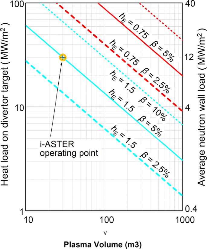
Heat power load on divertor targets, considering improved divertors and sweeping, with Kd = 20 and 50% of radiated power at edge, and average neutron wall load, plotted as functions of the plasma volume, for combinations of hE, βlim and minimum field for ignition presented in Fig. 1
-
3.
50% of the power is radiated by the plasma edge, also considered in Fig. 4.

The resulting heat loads are plotted in Fig. 4.
If such conditions are not met, it can be shown that ignition could be achieved by reducing β to ~ 2.5% or less and increasing B. This, however, would largely reduce the attractiveness of the approach, unless a solution is adopted—probably based on liquid lithium, which may withstand high Pd. As an added benefit, low recycling Li walls enhanced confinement in TFTR [52], TJ-II [53], NSTX [54] and other devices [55, 56] by various amounts, ranging between 25% and 100%. Liquid lithium does not erode or blister. Low Li impurity in the core plasma was obtained in NSTX and TFTR [55], which allowed low Zeff (~ 1.3), e.g. in TFTR [37]. Drawbacks of lithium utilization, like oxidation, fire risk, tritium retention and others are cited in Ref. [57].
It goes beyond the scope of the present paper to enter in excessive details on this aspect. However, it is worth mentioning several promising Li-based systems:
-
Jets of liquid metal droplets flowing on limiters or divertors. As an example, Ga-In-Sn droplets of 2–4 mm diameter and 2-5 m/s extracted 5-10 MW/m2 from the T–3 M tokamak [58, 59].
-
Liquid Li limiters or walls based on a Capillary Porous System (CPS), as tested in FTU [60, 61] and TJ-II [62]. In FTU they withstood an average of 2 MW/m2 and brief (300 ms) peak values of 5 MW/m2 (see Fig. 12 in Ref. [61]). Experiments with a CPS liquid lithium limiter on T-11 M tokamak [63] achieved 10 MW/m2 on the limiter (0.3 s pulse), and 30 MW/m2 including radiation from Li ions.
-
Beams of high speed (> 100 m/s) Li droplets [64], as theoretically proposed for the ITER divertor.
-
Molten (tin) shower jets are theorized for the FFHR reactor [65].
Indeed, promising high power extraction systems could be properly tested and enhanced in the present high power density approach.
The average neutron wall load (Fig. 4) is calculated as the total neutron power divided by the plasma surface.
Power Dissipated in Resistive Magnets
The effective cross section of the coils is maximized in order to reduce the coil resistance and lower the Ohmic power dissipated in the coils, as in Refs. [35, 66] and in Fig. 7. As a result of this design, each coil presents variable cross-section in poloidal direction. The cross sections tend to be smaller on the inboard of the stellarator and larger on the outboard (Fig. 7), leading respectively to a local increase and local reduction of dissipated power, partially compensating each other.
Ports are not defined in this initial model for electric calculations, but they will be small as explained in “Resistive Magnets” section and would not hinder the massive quasi-continuous coils.
A simple analytical expression is derived in “Analytic Approximation to Dissipated Power” section for the power dissipated in the coils. Some factors involved in that expression are computed in “Finite Elements Results” section with the aid of finite elements.
Analytic Approximation to Dissipated Power
An approximate analytical expression valid for any V, hE and βlim is sought here. The plasma cross-section is approximated by a circle (Fig. 5). The vessel and coils are conformal to the plasma. Let us introduce the ratio fR of the major radius of the magnetic axis to R (Rm = fR R); the factor ξ relating the minor radius of the winding surface, ac, to the plasma minor radius (ac = ξ a); the fractional thickness ε of the coils relative to a (e = ε a) and the fractional effective cross-section of the conductor, fi (ratio of copper cross-section SCu to total section SCu plus Si, Fig. 7). Finally, the coil-shape factor fs quantifies the increase of length and reduction of cross-section of the conductor due to coil twisting. Some of these parameters are illustrated in Fig. 5. In terms of these geometrical factors, the Ohmic power dissipated in coils of resistivity ρ is given by

Schematic poloidal cross-section of the plasma and a coil, and definition of the main dimensions used in the calculations
Accordingly, if we set ξ = 2, ε = 1, fs = 1.3, fR = 1.2, fi = 6/7 and adopt the minimum B required for ignition (Fig. 1) we obtain the dissipated power plotted in Fig. 6.

Approximate electric power consumed in the resistive copper coils for the parameters and minimum field for ignition presented in Fig. 1
Finite Elements Results
Coil shapes are generated for two quasi-isodynamic magnetic configurations (QIP3 and HSR3) by means of the CASTELL [67] and NESCOIL [68] codes. QIP3 is utilized as the main modelling magnetic configuration since quasi-isodynamic configurations have low plasma currents (may simplify the auxiliary coils and plasma control compared to quasi-axisymmetric ones), and in particular, QIP3 is a modern well optimized configuration of intermediate aspect ratio. The QIP3 coils are shown in Fig. 7.

Illustration of the concept of massive resistive coils of variable cross-section (variable-width)
Power dissipation is calculated by finite elements in the CASTELL code, using the configuration depicted in Fig. 7 except that we treat the trapezoidal cross-sections of that figure as rectangular. In addition, values ξ = 1.75, ε = 0.5 are used for QIP3, ξ = 2, ε = 1 for HSR3, and fi = 6/7 for both. It results that the analytical expression (9) agrees, with deviations lower than 20%, with the time-consuming finite elements calculation for QIP3 and HSR3, taking a fixed fs = 1.3 (in comparison, for a tokamak fs = 1). From the study performed for QIP3 and HSR3 configurations, 1.2 < fs < 1.4 is expected for typical stellarator magnetic configurations.
Current Density and Coil Temperature
The current density js in the coils is evaluated at the cross-sections S located at the major radius R (Fig. 5) and averaged over all coils. Nevertheless, the current density is higher in certain locations. We denote by fc the concentration factor for the maximum current density relative to js (jmax = fc js). fc is calculated by finite elements in CASTELL code as the ratio of the average cross section of all the finite elements for all the coils to the minimum cross section found among the coils. As an example, fc = 5 for QIP3 and fc = 6 for HSR3 was calculated for the conditions in “Finite Elements Results” section fc < ~ 6 is expected for non-quasi-isodynamic stellarators since there is not a mirror-like magnetic field.
The average increase of temperature of the copper at section S is calculated as
Being, t the pulse length (5 τE), Cp the volume-specific heat of the material, Pcoils total power dissipated in coils from Eq. (9), VtotCu total volume of copper in all coils, and the remainder as in “Power Dissipated in Resistive Magnets” section.
The maximum increase of temperature results
Limitations and Discussion
The large thickness of the magnets for reasonable power supplies is a concern. Thickness as wide as the plasma minor radius (ε = 1) is taken for Fig. 6. Despite that, additive manufacturing can help the fabrication of such thick layer(s) of conductor and insulation, as being investigated for stellarator coils in Refs. [69,70,71].
Also, the fabrication method for the variable cross-section coils requires future exploration. Water jet cutting of copper sheets and winding of the resulting conductors in additively manufactured grooves is a construction option. Another alternative is the use of a single, properly grooved thick metal layer conformal to the vacuum vessel, with insulating layers in the grooves, similarly to the concept depicted in Ref. [66].
The massive resistive coils of variable cross-section involve new calculation methodologies and advanced magnetic error prediction. The coil width, number of coils and the number of layers per coil has to be decided according to: i) finite element analysis of the current paths in the wide coils, and ii) the non-uniform increase of copper temperature and thus differential increase of resistivity due to Joule heating. Such advanced calculations will be investigated in next development phases.
Estimation of Stress in Coil Structures
The yield tensile strength of the coil support materials and insulation constrain the maximum achievable B.
In this section, first an analytic approximation is deduced and then a specific finite elements calculation is performed.
Analytic Approximation of Stress
Let us approximate the stellarator coils as if they were circular and uniformly distributed, in the toroidal direction, in a monolithic support of thickness d = ψ a .
Figure 8, complemented with Fig. 5, illustrate the notations.

Sketch for the analytical approximation
Here fout denotes a radial force acting on the outboard torus, and the field B is inversely proportional to the major radius R. Hence, dfout = Bout × I dL. After integration, we obtain the average stress σ s at section S:
with
Values of σs are plotted in Fig. 9 as a function of the plasma volume, for ψ = 0.5, ξ = 2 and A = 6.

Equation (12) can be approximated for ξ = 2 and A > 5 by
The maximum stress in the structure is σ max = fσ σs, where fσ is a stress concentration factor. Finite element calculations presented in the next section will show that fσ ~ 2 – 3, depending on the type of stellarator.
Finite Element Calculation
A monolithic toroidal support external to the coils for the QIP3 configuration (Fig. 7) was modelled in CATIA (Fig. 10) for the sake of the finite element calculations. This model is somewhat similar to the structures defined for the ARIES-CS and UST_1 stellarators [72,73,74].

Section view of the model for the FEA calculation
Loads due to the weight of the structure are not considered, and openings through the structure are neglected. The central ring is modelled as a thin hexagon in order to avoid impacting the calculation.
To fix the ideas, we set V = 30 m3, B = 9.8 T (see the hE = 1.5, βlim = 5% case in Fig. 1), ψ =0.5 and a current of 1.6 MA in each coil. Under these conditions, 3600 elements of force on 144 coils were calculated by the CASTELL code, introduced in the Finite Element Analysis (FEA) module of CATIA and, applied on the support structure. This model hinders the calculation of the stress in the coils and intercoil insulation.
The resulting Von Mises stress is shown in Fig. 11.

Von Mises stress on the surface of the monolithic support
The maximum stress in the monolithic support (σ max ~ 600 MPa) is located at the inboard of the curved section. Such value is 2.5 times higher than the result (σ s = 245 MPa) from Eq. (12), thus fσ = 2.5.
Limitations and Discussion
This initial stress calculation does not tackle the insulation stress, which remains for future detailed studies. High strength insulation might be required.
The type of magnetic configuration changes the location of the areas of maximum stress, i.e. [72], but the approach of considering an averaged value σs and an stress concentration factor fσ is still helpful.
Local adjustment or optimization of the thickness of the structure could smooth stress and deformation on the full structure.
In comparison to tokamaks, the larger aspect ratio of stellarators decreases the forces in the inboard of the torus [15] but the stress concentration factor in stellarators is unfavourable. In spite of this, the maximum stress in the monolithic support in i-ASTER resulted in similar levels to the maximum stress in the coil support of a high field tokamak like IGNITOR, ~ 500 MPa, [18].
Definition of i-ASTER
i–ASTER is a high-field, small size and resistive-magnet stellarator concept designed to reach ignition and study burning plasmas. It is not a power plant prototype.
Mission and General Characteristics
i-ASTER aims at, rapidly and at modest cost, achieving and understanding ignition, and studying alpha-particle physics in ignited or near-ignited plasmas in a small fusion device. This physics will be only partially investigated in ITER. Thanks to its high power-density, i–ASTER could serve the additional goal of testing and optimizing power extraction systems (e.g. lithium-based) and studying the plasma-wall interaction. Indirectly, it would complement the stellarator research line in the high plasma pressure range, advance technologies for high field fusion devices and for the manufacturing of strong stellarator magnets.
Pulses are foreseen to last few seconds (much longer than the energy confinement, alpha-particle slowing down time and other timescales of interest) and to be repeated with a low duty-cycle (~ 1000 pulses during a ~ 10 year lifetime). This approach reduces cost and neutronic issues and still accomplishes the research mission stated above. The duty-cycle is selected as an initial conservative value from estimations on neutronics effects (i.e. on copper resistivity) and, to achieve undemanding and slow cooling of coils between pulses. The model to perform such estimations is an ignition-capable stellarator working at the frontier of the physics and technological limits (minimum size device) whose size is independent of the duty cycle. The optimization of the device size based on the ratio of number of pulses to facility cost is out of scope of the present work.
In the spirit of reducing costs, and compatible with short pulses, i-ASTER adopts resistive magnets, which are faster to manufacture and simpler to operate than superconducting coils. Also, resistive magnets allow faster tests, avoid cryostat, cryoplant and cooldown time, allocate extra space for the plasma due to thinner shielding, simplify radioactive waste recycling and, thus, moderate costs.
Main Design Features of i-ASTER
The three essential technological characteristics of i–ASTER (massive resistive magnets, detachable periods and Li divertors-walls) are described in the three subsections below. Subsequently, four complementary features are mentioned.
Resistive Magnets
The external surface of the torus would be covered by a thick layer or multilayer of copper, forming a series of wide modular coils of variable cross section (Figs. 7 and 10). The magnets would work adiabatically and a minimal cooling system would remove the heat during the long time between consecutive pulses. Aluminium is a backup alternative to copper.
Only one section per period (Fig. 12) will contain small ports for pumping, diagnostics and plasma heating. The few ports will be small to maximize the toroidal and poloidal coverage by the copper coils. This is made possible by the fact that: (1) ECRH is expected to suffice to reach ignition (“Heating System” section). Several powerful ECRH beams can be concentrated in a small region (the port area). Thus, port space required for heating is much reduced. (2) The need for pumping conduits during the short pulse is almost avoided by the pumping effect of liquid Li. All the chemical elements reaching the Li-wall, except for the small amount of He generated during the short pulse, react fast with liquid Li. Certainly, the whole vacuum vessel acts as a powerful getter vacuum pump. (3) Access for maintenance will be provided by detachable stellarator sectors.

Concept of detachable (half)periods. The depicted large coils and vacuum interfaces are only a reference to understand the concept
Detachable (Half)Periods
The periods or half-periods of the stellarator shall be easily separated from adjacent periods for easy assembly and maintenance. A (half)period would be removed from the torus and immediately, a refurbished or new one would be installed in order to minimize the maintenance downtime, e.g. coil replacement, which will be critical in the future power plants. Detachable periods were previously studied for superconducting coils [75] and appear equally advantageous and easier to realize for resistive magnets. The accuracy of the re-assembly is a concern, but appropriate remote maintenance techniques are highly accurate [76, 77]. For example, a circular central ring (Fig. 12) would facilitate accurate reassembly. Larger twisted modular coils located at the vacuum vessel interfaces would facilitate (dis)assembly and port allocation (Fig. 12). Large modular coils were also planned in certain versions of NCSX stellarator [78].
Lithium Divertor-Wall
An island divertor [11, 79] and a first-wall almost entirely covered with low-temperature (low recycling) liquid lithium is planned for i-ASTER. The latter could be realized by electrostatic/centrifugal spraying or by evaporation [80] of lithium on a thin Capillary Porous System (CPS) mesh (~ 0.2 mm thickness), similarly to the approach in Ref. [62]. The mesh is locally heated during coating from inside the vacuum vessel for proper Li deposition in the capillary mesh. The CPS is located on a thick copper substrate (the first wall) coated with a thin protective film of a Li compatible material (W or Mo). The lithium in the CPS is solid before the plasma discharge, at room temperature or slightly higher, and it is liquefied after the pulse start. For simplicity, heaters [62] are not planned in the copper substrate. The copper substrate at the divertor target areas would reach surface temperature 1200–1300 °C (for 30 MW/m2 thermal load and 2 s pulse), which would melt Cu and volatilize Li. Dry (tungsten or CFC) divertor targets enduring ~ 30 MW/m2 heat load [81, 82] or, advanced Li-based systems (jets of droplets, beams of droplets or shower jets, “Power Load on Divertor Targets” section) to dissipate a fraction of the heat load before reaching the Li-CPS, would allow withstanding the intense heat load.
Pulse Length
Ignition conditions are to be maintained for few energy confinement times τE (5 τE assumed here, comparable to 10 τE in FIRE [19]). The discharge is approximately 40 times longer than the alpha-particle slowing down time [83], thus enabling the study of alpha particles and their confinement.
Distance from Plasma to Coils
The copper coils are as thick (ε = 1) and as far from the Last Closed Flux Surface (LCFS) (ξ = 2) as reasonably possible for a smooth plasma shape of the HSR3 type.
The distance from the LCFS to the internal surface of the modular coils is (“Power Dissipated in Resistive Magnets” section)
For ξ = 2, A = 6 and V = 30 m3, this gives Δ’ = 0.3 m.
No space is allocated for the breeding blankets in i–ASTER because breeding Tritium goes beyond the scope of the device. Besides, Δ’ is too small to accommodate a breeding blanket.
Heating System
The heating systems would only be used to ignite the plasma. The frequency needed for ECRH heating at B = 9.8 T, even at first harmonic, is unusually high (275 GHz), which will increase the cost of the gyrotrons. The cut-off density for O-mode ECRH is 9.2 × 10²⁰ m−3, slightly lower than required (Fig. 2). This implies that the plasma will be slightly overdense and will require the excitation of Electron Bernstein Waves by means of Ordinary-eXtraordinary-Bernstein mode conversion—a technique well-established in the W7-AS stellarator and elsewhere [84].
Essential Diagnostics Strategy
Detailed integration of plasma physics (e.g. magnetic configuration, experimental plan) and technology (e.g. coil design, access for diagnostics) shall be produced. In the current initial design, two main ports (Fig. 12) are considered available for diagnostics (“Resistive Magnets” section), which will be complemented with some small ports. The diagnostics shall be designed and accommodated in each port in a fully integrated manner, for miniaturization. In a first stage, the diagnostics would be committed to plasma operation and machine protection (characterization of density and temperature profiles, neutron diagnostics, monitoring Li divertor-wall conditions, and the few plasma control diagnostics needed in a stellarator). In a 2nd stage, they would be mostly dedicated to study energetic particle dynamics (e.g. alpha-particle induced instabilities, alpha-particle losses and confinement). The FIRE tokamak diagnostics [85] are a reference for i-ASTER.
Size and Materials for i-ASTER.v1 According to Limits
Values of hE = 1.5 and βlim = 5% are selected according to available experimental and theoretical data, “Assumptions and Governing Equations: Ignition Condition” section. Those values were experimentally proven in W7-AS and LHD respectively. The achievement of both values simultaneously is predicted for the W7-X stellarator, “Assumptions and Governing Equations: Ignition Condition” section.
Concerning divertors, and considering the hypothesis and calculations in “Power Load on Divertor Targets” section, 30 MW/m2 thermal power load on targets is obtained for V = 30 m3, Fig. 4. This power load is the practical limit for solid divertor targets [81, 82, 86], and a prospect for advanced Li-based systems as divertor targets, “Lithium Divertor-Wall” section.
A Zamak alloy (a commercial alloy of zinc, aluminium, copper and magnesium) is selected for the coil support structures. Zamak is non-ferromagnetic, easy to cast at low temperature (400–420 °C) in high-precision shapes, and has high yield strength Syield = 360 MPa for the ‘Zamak 2’ alloy.
A strength safety factor of 1.5 accounts for uncertainties on the materials, stress concentration due to the ports and other uncertainties. From “Analytic Approximation of Stress” section and Eq. (12) with ψ = 0.5, it is calculated σs =240 MPa = Syield-Zamak2 /1.5. However, σ max (“Finite Element Calculation” section) exceeds Syield–Zamak2 . For Zamak 2 (E ≈ 85 GPa) the maximum displacement calculated by finite element analysis is 11 mm for ψ = 0.5. This displacement would be too large since coil positioning and shapes should have a tolerance of 0.1% or better [87, 88], corresponding to about 4 mm for i-ASTER. Therefore, it will be necessary to locally increase the thickness of the structure to ψ > 0.5 and to install a central support ring so as to balance the stresses and reduce the maximum displacement. These matters will be studied in future development stages.
From the estimations and calculations performed in the paper, V = 30 m3 is selected for i–ASTER.v1 as a lower limit for the plasma volume, under the conditions and materials taken into account. Indeed, the main constraining parameters (power load on divertor targets, thickness of the coils, electric power to fed the coils, stress in the coil support, and maximum ΔT of insulation, see Table 2) are demanding, but technically possible.
i-ASTER Specifications
Table 2 summarises the specifications of i–ASTER.v1.
Discussion of the Specifications
Line-averaged plasma density up to n line = 4 × 10²⁰ m−3 was achieved in the High Density H-mode in W7-AS [11] and a central plasma density of 1021 m−3 was reached in LHD [89]. The feasibility of n line ~ 1021 m−3 should be experimentally proved, but, certainly, a high-field stellarator would favour high densities, according to the Sudo limit [21].
i-ASTER considers reactor-relevant β (5%) and adopts a high magnetic field B. As a result, the power density (∝ ~ β 2 B4) and the heat load on the divertor is high. This will be an opportunity to test and enhance high power extraction systems and plasma purity, for example, by lithium-based systems.
The evaluation of intermediate Q regimes and implications on the results (e.g. different divertor load) is beyond the scope of the present paper. These intermediate Q regimes might occur if ignition or near-ignition could not be achieved in i-ASTER.
The electric power required for the magnets is substantial, but appears tractable. For example, TFTR flywheels provided up to 0.7 GW [90].
The use of steel would reduce the thickness of the monolithic structure. Nonetheless, steel requires more expensive casting and machining than Zamak. Alternatively, laminated composite (Syield > 1000 MPa) shaped on additive manufacturing structures is envisaged, inspired by Refs. [69, 70].
Discussion on Neutronics
Neutron damage lower than 0.1 dpa is roughly estimated for the most exposed copper of the coils after 10 years lifetime (total of 1000 pulses, no shielding). This would produce some Cu embrittlement, but minor resistivity reduction and feasible insulation materials [91]. The estimation is based on the ratio rdpa-NLW of dpa per full-power-year (fpy) to the average neutron wall load (NWL), which is calculated from data in Refs. [92, 93] for ferritic–martensitic steels, resulting rdpa-NLW ~ 10 (dpa/fpy) / (MW/m2). For the i-ASTER wall surface and total neutron power, with duty cycle 6 x 10⁻⁶, ten years operation, peak NWL twice the average NWL [92], and dpa’s in copper 60% higher than in ferritic-martensitic steel [94], it results 0.03 dpa.
Concerning the neutron heating (‘n-heat’) of coils, a first approximation is obtained as: i) the DEMO n-heat at the first wall for ferritic-martensitic steel is taken, 8 W/cm3 [93], ii) n-heat for copper and iron are similar [95], iii) scaling n-heat to the plasma surface and neutron power in i-ASTER, with neutron shielding of 80%, resulting in n-heat ~ 14 W/cm3. For copper coil, an average ΔTaveNWL ~ 8 °C is calculated at the end of the 2 s pulse (ΔTpeakNWL ~ 16 °C).
Regarding the n-heat in the first-wall, following the previous procedure, without shielding, it results ΔTave ~ 40 °C (ΔTpeak ~ 80 °C).
No major neutronics difficulties are envisioned, thanks in part to the favourable high ratio of plasma surface to plasma volume in the relatively large aspect-ratio and small size i–ASTER.
Limitations and Discussion
Limitations
Different quasi-isodynamic magnetic configurations (QIP3, HSR3) were utilized for the models. A definitive magnetic configuration for i–ASTER is not yet decided and it will have some impact on the resulting parameters. For example, the magnetic configuration impacts the areas of stress concentration (“Limitations and Discussion” section) and the current density factor (“Current Density and Coil Temperature” section).
Calculations by complex systems codes [25] have not been carried out yet, and will be the subject of future work. However, the rough estimates presented may be sufficient for this initial stage of development.
It is unknown if the assumptions performed for the estimation of the power load on divertor targets (large wetted area, sweeping, 50% edge radiation) can be simultaneously achieved. Lowering β to ~ 2.5% or less and increasing B could still achieve ignition at lower divertor loads.
The initial stress calculation does not tackle the insulation stress. Also, the (small) ports have not been modelled. The strength safety factor considered in the study may cover the uncertainties. However, further calculations will be required as the geometrical design advances.
Refined neutronics calculations are required to estimate the neutron damage to coil insulation, activation and damage on copper, and neutron heating of first wall and coils.
Discussion
A quasi-isodynamic configuration was assumed for i–ASTER in order to advance the design. Currently, there is no universally accepted criterion to decide a best type of quasi-symmetry, and it advises against an early decision on the definitive i–ASTER magnetic configuration.
Optimization of stellarator magnetic configurations continues worldwide [25, 96,97,98] and new stellarator concepts continue to emerge [96, 99]. Hence, future versions of i-ASTER might have larger A, which usually gives higher beta limit βlim (“Assumptions and Governing Equations: Ignition Condition” section, [30]), or higher number of field periods. There is not any property (number of periods, type of quasi-symmetry) of the selected QIP3 and HSR3 configurations that makes them unique for the mission and engineering approach of i–ASTER. Only, the intended small size of the device favours moderate aspect ratio.
Power extraction systems (e.g. solid divertor targets, flowing liquid metals) are critical for the attractiveness of fusion as a competitive energy source [47]. The liquid–metal option has been favoured for i-ASTER due to its high theoretical potential, e.g. high speed metal droplet beams [64] or molten tin shower jets [65], despite the comparatively limited level of development.
The massive resistive coils of variable cross-section involve new calculation methodologies that have only been initiated and represent a novel field of study.
Resistive magnets may not be the best option for stellarator power plants. Nevertheless, the requirement of simplification suggests this option for a first ignition experimental device.
If it is reasonable to study high-field ignition-capable tokamaks like IGNITOR and FIRE, it appears reasonable to explore the potential of high-field stellarators of comparable size and magnetic field.
Summary and Conclusions
Wide ranges of physics and engineering parameters have been explored, in search for the conditions enabling ignition in a small-size, high-field stellarator experiment. The magnets are resistive to contain construction costs. Specifically, massive copper coils of variable cross-section are envisaged to reach high fields with feasible power supplies. A monolithic toroidal coil support structure, external to the coils, is also proposed. Analytic expressions and finite-element calculations were produced for the power consumed in the magnets and the stress in the monolithic support. Plots were generated for all the relevant parameters, under a variety of assumptions on the energy confinement enhancement factor hE, stability beta limit βlim and plasma volume. From this parametric study, a preliminary conceptual design of a high-field ignition-capable experimental stellarator (i–ASTER) has emerged, based on a quasi-isodynamic magnetic configuration. i–ASTER presents three distinctive features: massive resistive coils of variable cross-section, detachable periods and lithium-coated walls and divertors. i–ASTER.v1 has a plasma volume of 30 m3 and an average magnetic field B ~ 10 T on axis, comparable with the IGNITOR and FIRE tokamak designs.
No unsurmountable difficulties have been found for this high-field pulsed stellarator approach to ignition experiments. The main concern is the possibly intractable power load on divertor targets and subsequent impurity influx. This could be tackled by lowering the operating β and using lithium-based power extraction systems. The considerable radial thickness of the magnets is also a concern, but additive manufacturing could lessen this issue.
This work is undertaken in order to fill a gap in the knowledge of high-field ignition-capable fusion devices of the stellarator type, which were significantly studied for tokamaks in the IGNITOR and FIRE tokamak concepts, and proposes a high-field resistive-magnet stellarator path towards the study of burning plasmas.
The definition and detailed calculation of the magnetic configuration and the 3D coil structure will be the subject of future work. Additive manufacturing of the coil support structure will also be further investigated. Detailed neutronics and more detailed mechanical and electric calculations will be performed in the next development stages.
References
M.I. Hoffert, K. Caldeira, G. Benford, D.R. Criswell, C. Green, H. Herzog et al., Advanced technology paths to global climate stability: energy for a greenhouse planet. Science 298, 981–987 (2002)
J. Ongena, R. Koch, R. Wolf, H. Zohm, Magnetic-confinement. Nat. Phys. 12, 398–410 (2016)
E.A. Azizov, Tokamaks: from A D Sakharov to the present (the 60-year history of tokamaks). Phys. Uspekhi 55, 190–203 (2012)
P. Helander, C.D. Beidler, T.M. Bird, M. Drevlak, Y. Feng, R. Hatzky et al., Stellarator and tokamak plasmas: a comparison. Plasma Phys. Control. Fusion 54, 124009 (2012)
C. Beidler, G. Grieger, F. Herrnegger, E. Harmeyer, J. Kisslinger et al., Physics and engineering design for W7-X. Fusion Technol. 17, 148–167 (1990)
O. Motojima, K. Akaishi, K. Fujii, S. Fujiwaka, S. Imagawa, H. Ji et al., Physics and engineering design studies on the Large Helical Device. Fusion Eng. Des. 20, 3–14 (1993)
H. Wobig, T. Andreeva, C.D. Beidler, E. Harmeyer, F. Herrnegger, Y. Igitkhanov et al., Concept of a Helias ignition experiment. Nucl. Fusion 43, 889–898 (2003)
F. Warmer, C.D. Beidler, A. Dinklage, R. Wolf, The W7-X Team, From W7-X to a HELIAS fusion power plant: motivation and options for an intermediate step burning-plasma stellarator. Plasma Phys. Control. Fusion 58, 074006 (2016)
J. Wesson, Tokamaks, 4th edn. (Oxford University Press, Oxford, 2011). ISBN 9780199592234
T. Sunn Pedersen, M. Otte, S. Lazerson, P. Helander, S. Bozhenkov, C. Biedermann et al., Confirmation of the topology of the Wendelstein 7-X magnetic field to better than 1:100,000. Nat. Commun. 7, 13493 (2016)
M. Hirsch, J. Baldzuhn, C. Beidler, R. Brakel, R. Burhenn, A. Dinklage et al., Major results from the stellarator Wendelstein 7-AS. Plasma Phys. Control. Fusion 50, 053001 (2008)
T. Hartkopf, et al., R&D needs and required facilities for the development of fusion as an energy source, report of the fusion facilities review panel, European Commission, EURATOM (2008)
D.A. Gates, D. Anderson, S. Anderson, M. Zarnstorff, D.A. Spong, H. Weitzner et al., Stellarator research opportunities: a report of the national stellarator. J. Fusion Energ 37, 51–94 (2018)
H. Hutchinson, H. Becker, P. Bonoli, N. Diatchenko, S. Fairfax, C. Fiore, et al., The physics and engineering of alcator C-MOD, Report PFC/RR-88-11, Plasma Fusion Center, MIT (USA) (1988)
D. Bruce Montgomery, High field magnetic confinement of fusion plasmas, strong and ultrastrong magnetic fields and their applications. Top. Appl. Phys. 57, 205–246 (2005)
E.S. Marmar, S.G. Baek, H. Barnard, P. Bonoli, D. Brunner, J. Candy et al., Alcator C-Mod: research in support of ITER and steps beyond. Nucl. Fusion 55, 104020 (2015)
G. Pucella, E. Alessi, L. Amicucci, B. Angelini, M.L. Apicella, G. Apruzzese et al., Overview of the FTU results. Nucl. Fusion 55, 104005 (2015)
B. Coppi, A. Airoldi, R. Albanese, G. Ambrosino, F. Bombarda, A. Bianchi, New developments, plasma physics regimes and issues for the Ignitor experiment. Nucl. Fusion 53, 104013 (2013)
D. Meade, S. Jardin, C. Kessel, J. Mandrekas, M. Ulrickson et al., FIRE, exploring the frontiers of burning plasma science. J. Plasma Fusion Res. SER. 5, 143–148 (2002)
A. Sagara, O. Mitarai, T. Tanaka, S. Imagawa, Y. Kozaki, M. Kobayashi, T. Morisaki et al., Optimization activities on design studies of LHD-type reactor FFHR. Fusion Eng. Des. 83, 1690–1695 (2008)
A. Weller, K.Y. Watanabe, S. Sakakibara, A. Dinklage, H. Funaba, J. Geiger et al., International Stellarator/Heliotron Database progress on high-beta confinement and operational boundaries. Nucl. Fusion 49, 065016 (2009)
S. Sudo et al., Scalings of energy confinement and density limit in stellarator heliotron devices. Nucl. Fusion 30, 11–21 (1990)
M.A. Green, B.P. Strauss, The cost of superconducting magnets as a function of stored energy design magnetic induction times the field volume. IEEE Trans. Appl. Supercond. 18(2), 248–251 (2008)
Y. Turkin, C.D. Beidler, H. Maaßberg, S. Murakami, V. Tribaldos, A. Wakasa, Neoclassical transport simulations for stellarators. Phys. Plasmas 18, 022505 (2011)
F. Warmer, S.B. Torrisi, C.D. Beidler, A. Dinklage, Y. Feng, J. Geiger et al., System code analysis of HELIAS-Type fusion reactor and economic comparison with tokamaks. IEEE Trans. Plasma Sci. 44, 1576–1585 (2016)
A. Komori, H. Yamada, S. Sakakibara, O. Kaneko, K. Kawahata, T. Mutoh et al., Development of net-current free heliotron plasmas in the LHD. Nucl. Fusion 49, 104015 (2009)
L.E. Sugiyama, H.R. Strauss, W. Park, G.Y. Fu, J.A. Breslau, J. Chen, Two-fluid limits on stellarator performance. , in Proc. of the 20 IAEA fusion energy conference, Vilamoura (Portugal), 1–6 Nov 2004, TH/P2-30
M.C. Zarnstorff for the NCSX Team, The Role of NCSX in the World Fusion Program, Presentation in FESAC Scientific and Programmatic Review of NCSX, 15 September 2007
L.P. Ku, A.H. Boozer, New classes of quasi-helically symmetric stellarators. Nucl. Fusion 51, 013004 (2011)
M. J. Mikhailov, et al., Comparison of the properties of Quasi-isodynamic configurations for different number of periods, in Proc. of the 31st EPS Conf. on Plasma Phys. London, 28 June–2 July 2004, ECA 28G (2004) P-4.166
C.D. Beidler, K. Allmaier, MYu. Isaev et al., Benchmarking of the mono-energetic transport coefficients: results from the international collaboration on neoclassical transport in stellarators. Nucl. Fusion 51, 076001 (2011)
A.S. Ware, D. Westerly, E. Barcikowski, L.A. Berry, G.Y. Fu, S.P. Hirshman et al., Second ballooning stability in high-β, compact stellarators. Phys. Plasmas 11, 2453–2458 (2004)
A.S. Ware, S.P. Hirshman, D.A. Spong, L.A. Berry, A.J. Deisher, G.Y. Fu, High-β equilibria of drift-optimized compact stellarators. Phys. Rev. Lett. 89, 125003 (2002)
G. Van Oost, E. Rebhan, Thermonuclear burn criteria. Trans. Fusion Sci. Technol. 53, 16–26 (2008)
V. Queral, J.A. Romero, J.A. Ferreira, High-field pulsed Allure Ignition Stellarator. Stellarator News 125, 7–10 (2010)
T.J. Dolan, Fusion Research (Pergamon Press, Oxford, 1980). ISBN 0-08-025565-5
D. K. Mansfield, Overview of TFTR Li experiments, Presentation in SNL Albuquerque NM, 13–17 November 2000
C. D. Beidler, E. Harmeyer, F. Herrenegger, et al., Stellarator fusion reactors - an overview, in Proc. of the 12 Int. Toki Conf. on plasma phys. and contr. nuclear fusion, APFA’01, ISBN 4-9900586-7-4, (2003) 149–155
F. Najmabadi, A.R. Raffray, ARIES-CS TEAM, The ARIES-CS compact stellarator fusion power plant. Fusion Sci. Tech. 54, 655–672 (2008)
Yu. Igitkhanov, T. Andreeva, C.D. Beidler, E. Harmeyer, F. Herrnegger, J. Kisslinger et al., Status of HELIAS reactor studies. Fusion Eng. Des. 81, 2695–2702 (2006)
N. Ohyabu, T. Morisaki, S. Masuzaki et al., Observation of stable superdense core plasmas in the large helical device. Phys. Rev. Lett. 97, 055002 (2006)
M. Shoji, S. Masuzaki, M. Kobayashi et al., Investigation of the helical divertor function and the future plan of a closed divertor for efficient particle control in the LHD plasma periphery. Fusion Sci. Tech. 58, 208–219 (2010)
M. Kotschenreuther, P. Valanju, S. Mahajan et al., The super X divertor (SXD) and a compact fusion neutron source (CFNS). Nucl. Fusion 50, 035003 (2010)
R. König, P. Grigull, K. McCormick, Y. Feng, J. Kisslinger, A. Komori et al., The divertor program in stellarators. Plasma Phys. Control. Fusion 44, 2365–2422 (2002)
R.E.H. Clark, D. Reiter, Nuclear Fusion Research: Understanding Plasma-Surface Interactions (Springer, Berlin, 2005). ISBN 978-3-540-27362-2
R. Aymara, V.A. Chuyanova, M. Huguetb, Y. Shimomurab, ITER joint central team and ITER home teams, overview of ITER-FEAT: the future international burning plasma experiment. Nucl. Fusion 41, 1301 (2001)
M.A. Abdou, The APEX Team, Exploring novel high power density concepts for attractive fusion systems. Fusion Eng. Des. 45, 145–167 (1999)
P.M. Valanju, M. Kotschenreuther, S.M. Mahajan, Super X divertors for solving heat and neutron flux problems of fusion device. Fusion Eng. Des. 85, 46–52 (2010)
H. Renner, J. Boscary, H. Greuner, H. Grote, F.W. Hoffmann, J. Kisslinger et al., Divertor concept for the W7-X stellarator and mode of operation. Plasma Phys. Control. Fusion 44, 1005 (2002)
M. Li, F. Maviglia, G. Federici, J. You, Sweeping heat flux loads on divertor targets: thermal benefits and structural impacts. Fusion Eng. Des. 102, 50–58 (2016)
Y. Nakamura, S. Masuzaki, T. Morisaki, H. Ogawa, T. Watanabe et al., Impact of real-time magnetic axis sweeping on steady state divertor operation in LHD. Nucl. Fusion 46, 714–724 (2006)
D.K. Mansfield, K.W. Hill, J.D. Strachan et al., Enhancement of Tokamak Fusion Test Reactor performance by lithium conditioning. Phys. Plasmas 3(5), 1892–1897 (1996)
J. Sánchez, M. Acedo, A. Alonso et al., Confinement transitions in TJ-II under Li-coated wall conditions. Nucl. Fusion 49, 104018 (2009)
M.G. Bell, H.W. Kugel, R. Kaita et al., Plasma response to lithium-coated plasma-facing components in the National Spherical Torus Experiment. Plasma Phys. Control. Fusion 51, 124054 (2009)
R. Majeski, Liquid metal walls, lithium, and low recycling boundary conditions in tokamaks, in Report PPPL-4480, Proc. 3rd ITER International Summer School, Aiex‐en‐Provence (France), 22–26 June 2009, AIP Conf. Proc. vol. 1237, pp. 122–137 (2010)
Yoshi Hirooka, A review of plasma–wall boundary effects on core confinement and lithium applications to boundary-controlled magnetic fusion exp. Fusion Eng. Des. 85, 838–846 (2010)
R.E. Nygren, F.L. Tabarés, Liquid surfaces for fusion plasma facing components–a critical review, Part I: physics and PSI. Nucl. Mater. Energy 9, 6–21 (2016)
S.V. Mirnov, V.N. Demyanenko, E.V. Muravev, Liquid-metal tokamak divertors. J. Nucl. Mater. 45–49, 196–198 (1992)
B.G. Karasev, I.V. Lavrentjev, A.F. Kolesnichenko et al., Research and development of liquid metal systems for a tokamak reactor. Fusion Eng. Des. 8, 283–288 (1989)
G. Mazzitelli, M.L. Apicella, D. Frigione, G. Maddaluno, M. Marinucci, C. Mazzotta et al., FTU results with a liquid lithium limiter. Nucl. Fusion 51, 073006 (2011)
G. Mazzitelli, M.L. Apicella, V. Pericoli Ridolfini, G. Apruzzese, R. De Angelis, D. Frigione, Review of FTU results with the liquid lithium limiter. Fusion Eng. Des 85, 896–901 (2010)
A.V. Vertkov, I.E. Lyublinski, F. Tabares, E. Ascasibar, Status and prospect of the development of liquid lithium limiters for stellarator TJ-II. Fusion Eng. Des. 87, 1755–1759 (2012)
S.V. Mirnov, E.A. Azizov, V.A. Evtikhin, V.B. Lazarev, I.E. Lyublinski et al., Experiments with lithium limiter on T-11 M tokamak and applications. Plasma Phys. Control Fusion 48, 821–837 (2006)
K. A. Werley, ‘A high-speed beam of lithium droplets for collecting diverted energy and particles in ITER’, Los Alamos N. L. report LA-UR–89-3268 (1989)
A. Sagara, J. Miyazawa, H. Tamura, T. Tanaka, T. Goto, N. Yanagi et al., Two conceptual designs of helical fusion reactor FFHR-d1 based on ITER technologies and challenging ideas. Nucl. Fusion 57, 086046 (2017)
F.A. Volpe, C. Caliri, A.W. Clark, A. Febre, K.C. Hammond, Y. Kornbluth, et al., Stellarator Research at Columbia University, Presentation given in PPPL (2013)
V. Queral, Rapid manufacturing methods for geometrically complex nuclear fusion devices: The UST_2 stellarator, PhD Thesis, 2015
P. Merkel, Solution of stellarator boundary value problems with external currents. Nucl. Fusion 27, 867 (1987)
V. Queral, 3D-printed fusion components concepts and validation for the UST_2 stellarator. Fusion Eng. Des. 96, 343–347 (2015)
V. Queral, Concept, production and validation of a 3D-printed coil frame for the UST2 modular stellarator. Fusion Eng. Des. 89, 2145–2149 (2014)
V. Queral, E. Rincón, V. Mirones, L. Rios, S. Cabrera, Dimensional accuracy of additively manufactured structures for modular coil windings of stellarators. Fusion Eng. Des. 124, 173–178 (2017)
X.R. Wang, A.R. Raffray, L. Bromberg, J.H. Schultz, L.P. Ku, J.F. Lyon et al., Aries-CS magnet conductor and structure evaluation. Fusion Sci. Technol. 54, 818–837 (2008)
V. Queral, Coil fabrication of the UST_1 modular stellarator and potential enhancements. Fusion Eng. Des. 88, 683–686 (2013)
V. Queral, Design, construction and validation of the UST_1 modular stellarator. Fusion Eng. Des. 112, 410–417 (2016)
X.R. Wang et al., Maintenance approaches for ARIES-CS compact stellarator power core. Fusion Sci. Technol. 47(4), 1074–1078 (2005)
D.R. Doman compilation, design guides for radioactive material handling facilities and equipment, American Nuclear Society, (1988). ISBN: 0-89448-554-7
V. Queral, A. García, G. Miccichè, A. Ibarra, N. Casal, F. Mota, D. Rapisarda, Proposal of an improved design of IFMIF test cell components for enhanced handling and reliability. Fusion Eng. Des. 84, 1548–1552 (2009)
H.E. Mynick, N. Pomphrey, S. Ethier, Exploration of stellarator configuration space with global search methods. Phys. Plasmas 9, 869–876 (2002)
Y. Feng, C.D. Beidler, J. Geiger, P. Helander, H. Hölbe, H. Maassberg et al., On the W7-X divertor performance under detached conditions. Nucl. Fusion 56, 126011 (2016)
F.L. Tabarés et al., Plasma performance and confinement in the TJ-II stellarator with lithium-coated walls. Plasma Phys. Control. Fusion 50, 124051 (2008)
P. Gavila, B. Riccardi, S. Constans, J.L. Jouvelot, I. Bobin Vastra et al., High heat flux testing of mock-ups for a full tungsten ITER divertor. Fusion Eng. Des. 86, 1652–1655 (2011)
A.R. Raffray, J. Schlosser, M. Akiba, M. Araki, S. Chiocchio et al., Critical heat flux analysis and R&D for the design of the ITER divertor. Fusion Eng. Des. 45, 377–407 (1999)
D.J. Sigmar, R. Gormley, G. Kamelander, Effects of anomalous alpha particle diffusion on fusion power coupling into tokamak plasma. Nucl. Fusion 33, 677–686 (1993)
H.P. Laqua, Electron Bernstein wave heating and diagnostic. Plasma Phys. Control. Fusion 49, R1 (2007)
K.M. Young, Challenges for plasma diagnostics in a next step device (FIRE), in Proceedings of the 19th SOFE, January 22–25, p. 192 (2002)
P. Gavila, B. Riccardi, G. Pintsuk et al., High heat flux testing of EU tungsten monoblock mock-ups for the ITER divertor. Fusion Eng. Des. 98–99, 1305–1309 (2015)
A.F. Almagri, D.T. Anderson, S.F.B. Anderson, K.M. Likin, P.G. Matthews, T.L. Piccione et al., Design and construction of HSX: a helically symmetricstellarator. J. Plasma Fusion Res. SERIES 1, 422–425 (1998)
J.H. Feist, M. Wanner and the W7-X construction team, Status of Wendelstein 7-X construction, in 28th EPS Conference on Controlled Fusion and Plasma Physics, Funchal (Portugal), 18–22 June 2001, ECA 25A pp. 1937–1940 (2001)
R. Sakamoto, M. Kobayashi, J. Miyazawa, S. Ohdachi, H. Yamada et al., High-density plasma with internal diffusion barrier in the large helical device. Nucl. Fusion 49, 085002 (2009)
R.J. Thome (Editor) et al., poloidal field coil system design for the compact ignition Tokamak, (CIT), Report PFC/RR-86-11, MIT, Massachusetts (USA) (1986)
H. Liu, M.A. Abdou, R.J. Reed, A. Ying, M.Z. Youssef, Neutronics assessment of the shielding and breeding requirements for FNSF. Fusion Eng. Des. 85, 1296–1300 (2010)
L. El-Guebaly, P. Wilson, D. Henderson, M. Sawan, G. Sviatoslavsky, T. Tautges et al., Designing ARIES-CS compact radial build and nuclear system: neutronics, shielding, and activation. Fusion Sci. Technol 54, 747–770 (2008)
I. Palermo, D. Rapisarda, I. Fernández-Berceruelo, A. Ibarra, Optimization process for the design of the DCLL blanket for the European DEMOnstration fusion reactor according to its nuclear performances. Nucl. Fusion 57, 076011 (2017)
J. Park, K. Im, S. Kwon, J. Kim, D. Kim et al., Nuclear analysis of structural damage and nuclear heating on enhanced K-DEMO divertor model. Nucl. Fusion 57, 126044 (2017)
A. Kumar, M.Z. Youssef, M.A. Abdou, Direct nuclear heating measurements in fusion neutron environment and analysis. Fusion Eng. Des. 18, 397–405 (1991)
D.A. Gates, A.H. Boozer, T. Brown, J. Breslau, D. Curreli, M. Landreman et al., Recent advances in stellarator optimization. Nucl. Fusion 57, 126064 (2017)
C. Zhu, S.R. Hudson, Y. Song, Y. Wan, New method to design stellarator coils without the winding surface. Nucl. Fusion 58, 016008 (2018)
H. Allen, Boozer, Stellarator design. J. Plasma Phys. 81, 515810606 (2015)
A.A. Subbotin, M.I. Mikhailov, V.D. Shafranov, MYu. Isaev, C. Nührenberg, J. Nührenberg et al., Integrated physics optimization of a quasi-isodynamic stellarator with poloidally closed contours of the magnetic field strength. Nucl. Fusion 46, 921 (2006)
Acknowledgements
The authors are grateful to M.I. Mikhailov, J. Nührenberg et al. [30] for supplying the QIP3 magnetic configuration, to A. Werner, J. Baldzuhn and J. Geiger for providing the coil definition of HSR3, and to E. Blanco and K.J. McCarthy for proof reading. The first author acknowledges J.A. Romero and J.A. Ferreira for longstanding discussions about fusion and stellarators. The work is partially funded by the Spanish ‘Ministry of Economy and Competitiveness’ under the grant number ENE2015-64981-R (MINECO / FEDER, EU). This work is partly supported by the US Department of Energy under Contract DE-AC05-00OR22725 with UT-Battelle, LLC and the US DOE.
Author information
Authors and Affiliations
Corresponding author
Rights and permissions
Open Access This article is distributed under the terms of the Creative Commons Attribution 4.0 International License (http://creativecommons.org/licenses/by/4.0/), which permits unrestricted use, distribution, and reproduction in any medium, provided you give appropriate credit to the original author(s) and the source, provide a link to the Creative Commons license, and indicate if changes were made.
About this article

Cite this article
Queral, V., Volpe, F.A., Spong, D. et al. Initial Exploration of High-Field Pulsed Stellarator Approach to Ignition Experiments. J Fusion Energ 37, 275–290 (2018). https://doi.org/10.1007/s10894-018-0199-5
Published:
Issue Date:
DOI: https://doi.org/10.1007/s10894-018-0199-5