
Abstract
Many database management systems (DBMS) need to ensure atomicity and isolation of transactions for logical data consistency, as well as to guarantee temporal correctness of the executed transactions. Since the mechanisms for atomicity and isolation may lead to breaching temporal correctness, trade-offs between these properties are often required during the DBMS design. To be able to address this concern, we have previously proposed the pattern-based UPPCART framework, which models the transactions and the DBMS mechanisms as timed automata, and verifies the trade-offs with provable guarantee. However, the manual construction of UPPCART models can require considerable effort and is prone to errors. In this paper, we advance the formal analysis of atomic concurrent real-time transactions with tool-automated construction of UPPCART models. The latter are generated automatically from our previously proposed UTRAN specifications, which are high-level UML-based specifications familiar to designers. To achieve this, we first propose formal definitions for the modeling patterns in UPPCART, as well as for the pattern-based construction of DBMS models, respectively. Based on this, we establish a translational semantics from UTRAN specifications to UPPCART models, to provide the former with a formal semantics relying on timed automata, and develop a tool that implements the automated transformation. We also extend the expressiveness of UTRAN and UPPCART, to incorporate transaction sequences and their timing properties. We demonstrate the specification in UTRAN, automated transformation to UPPCART, and verification of the traded-off properties, via an industrial use case.
1 Introduction
Many modern computer systems rely on database management systems (DBMS) to maintain the logical consistency of critical data, such as to ensure the correct balance of bank accounts during a bank transfer. By employing a variety of transaction management mechanisms, DBMS ensures logical data consistency under complex data management scenarios, such as transaction abortions and concurrent access of data. Among these mechanisms, abort recovery (AR) restores the consistent state of a database when a transaction is aborted due to errors and thus achieves atomicity [1]. Rollback, for instance, is a common AR technique that undoes all changes of an aborted transaction [1]. Concurrency control (CC) regulates concurrent access to data from different transactions, which prevents inconsistent data due to interference, and ensures isolation [1]. A widely adopted CC technique is to apply locks on the data such that arbitrary access is prevented [2]. Together, AR and CC ensure the logical consistency of critical data that the applications rely on, hence contributing to the dependability of the overall systems.
In addition to logical data consistency, another important factor to the dependability of many database-centric systems is the temporal correctness of transactions. Examples of systems where the temporal property is crucial include industrial control systems [3] and automotive systems [4], whose configurations and states can be stored in databases. Reading an outdated sensor value or calibration parameter could result in catastrophic consequences such as loss of lives. Finishing a transaction too late could cause the production process to fall behind schedule and lead to economic loss. In such real-time database systems, transactions must be temporally correct, meaning that they must be scheduled to use fresh data, and have to meet specified deadlines [5].
The assurance of atomicity and isolation, however, may stand at odds with enforcing temporal correctness, because CC may cause a transaction to be blocked for a long time, and AR often introduces extra workload when performing recovery. To make matters worse, some CC algorithms may directly abort transactions, while the recovery may again lock the data and block other transactions further, which entails complex behaviors in time and could lead to deadline misses. Therefore, designing a real-time DBMS (RTDBMS) requires careful trade-offs in transaction management [6], with respect to deciding on proper “variants” [7] of atomicity and isolation, as well as selecting proper AR and CC mechanisms. To achieve an appropriate trade-off, it is helpful to specify all three properties explicitly, together with their supporting AR, CC, and scheduling mechanisms, in a high-level language if possible familiar to system designers. To ensure the correctness of the trade-off, one should be able to analyze such specifications, and reason about whether the properties can be satisfied with the selected mechanisms.
This paper builds on top of our previous work [8], in which we took an initial step to specify and verify atomicity, isolation and temporal correctness in a unified framework. We proposed a Unified Modeling Language (UML) [9] profile called UML for TRANsactions (UTRAN), for the specification of transactions with atomicity, isolation and temporal correctness properties. UTRAN models a transaction as an activity, and includes explicit modeling elements to express atomicity and isolation variants, as well as the AR, CC and scheduling mechanisms. We also proposed a formal framework, called UPPAAL for Concurrent Atomic Real-time Transactions (UPPCART) [8], which models real-time transactions, together with the selected AR, CC and scheduling mechanisms in the RTDBMS, as a network of UPPAAL timed automata (TA) [10]. Constituents of the UPPCART models are formulated as automata patterns, such that the complexity of the models is tamed, and reuse of repeatable modeling pieces is enabled. The transactional properties can then be formalized, and verified rigorously using the state-of-the-art UPPAAL model checker [10]. The connection between UTRAN and UPPCART, however, is still not formally defined, which prohibits automated transformation for practices in complex systems. As a result, the current construction of UPPCART models requires considerable manual efforts and is prone to error.
In this paper, we contribute to the specification and verification of atomic concurrent real-time transactions in several aspects. We extend UTRAN and UPPCART to support sequences of transactions, and their end-to-end deadlines. Many real-time system designs contain invocation dependencies between transactions, that is, one transaction is started only after the termination of another. For instance, an update transaction executed by a sensor may trigger another transaction that updates the speed of the vehicle. In such cases, it is the end-to-end execution of the entire sequence that matters to the system validation. Therefore, we extend our UTRAN and UPPCART so as to cater for the specification and analysis of transaction sequences.
In order to help system designers to create well-formed UTRAN specifications, we enhance the UTRAN definition with static semantics constraints, defined in the Object Constraint Language (OCL) [11]. Specification errors violating the OCL constraints can be directly spotted by common UML editors, such as Eclipse PapyrusFootnote 1 and IBM Rational Software Architect (RSA)Footnote 2.
We bridge the gap between UTRAN and UPPCART in this paper, such that automated transformation is facilitated. To achieve this, we first propose formal definitions of UPPCART patterns and connectors, in terms of UPPAAL TA, based on which we are able to define the pattern-based construction for UPPCART models. This formalism enables us to create a translational semantics that maps the syntactic structures in UTRAN with the UPPCART patterns, which provides UTRAN with a formal semantics relying on timed automata. The translation process is implemented in our tool U\(^{2}Transformer\) [12], which transforms high-level UTRAN specifications, into verifiable UPPCART models.
We also present an industrial use case to demonstrate the specification, transformation, and verification of transactions using the extended UTRAN and UPPCART. The use case involves multiple construction vehicles working autonomously in a quarry, with requirements on collision avoidance and mission efficiency. To achieve this, we design a two-layer collision avoidance system to moderate the behaviors of the vehicles. Among them, the global collision avoidance layer is backed by an RTDBMS that stores the map of the quarry, and prevent vehicles colliding into each other via concurrency control. The local layer utilizes a local RTDBMS for ambient data that are used for obstacle avoidance by individual vehicles. We use UTRAN to specify the transaction sequences and transactions in both layers, as well as the properties to be ensured. We then transform these specifications into UPPCART models with U\(^{2}\)Transformer, and verify the correctness of our design.
In brief, our contributions in this paper are listed as follows:
-
extensions of UTRAN and UPPCART for transaction sequences;
-
OCL constraints for UTRAN;
-
a formal definition of pattern-based construction for UPPCART;
-
a translational semantics from UTRAN to UPPCART, and tool-supported transformations based on this;
-
a use case that demonstrates UTRAN, UPPCART, the transformation, and the verification.
The remainder of the paper is organized as follows. In Sect. 2, we present the preliminaries of the paper. In Sect. 3, we recall and extend the UTRAN profile. Section 4 introduces the formal definition of pattern-based construction, as well as the extended UPPCART framework. We propose the translational semantics of UTRAN to UPPCART, as well as our automated transformation, in Sect. 5, followed by our use case in Sect. 6. We discuss the related work in Sect. 7, after which we conclude the paper and outline future work in Sect. 8.
2 Preliminaries
In this section, we present the preliminaries of this paper, including the concepts of transactions, atomicity, isolation and temporal correctness (Sect. 2.1), UML profiles (Sect. 2.2), and UPPAAL timed automata (Sect. 2.3).
2.1 Real-time transactions
A DBMS models read and write operations of data as transactions, and handles data consistency via transaction management. Traditionally, a transaction is a partially ordered set of logically-related operations that as a whole ensures the ACID properties [1]: atomicity (a transaction either runs completely or makes no changes at all), consistency (transactions executed alone must ensure logical constraints), isolation (concurrent transactions do not interfere with each other), and durability (committed changes are made permanent). The set of operations is called a work unit (WU). The scope of a transaction is usually defined by the following operations: begin (start a transaction), commit (terminate a transaction and make its changes permanent and visible), and abort (terminate a transaction and recover from its changes). We consider two types of aborts in a database system: system aborts are caused by system errors or data contentions and thus are issued by the DBMS. User aborts are started by clients to stop the transaction on the purpose of fulfilling application semantics.
As complements to the classical transaction model with full ACID assurance, a number of other transaction models that define different variants of transaction properties have been proposed, as well as the mechanisms to realize them [7]. In this paper, we focus on the variants of atomicity, isolation, and temporal correctness.
2.1.1 Atomicity
Full atomicity achieves an “all-or-nothing” semantics, in which “commit” means completing “all” changes included in the transaction, while “abort” means that “nothing” is changed at all. In this paper, we particularly emphasize the recovery of transactions terminated by errors, and focus on the variants of atomicity upon transaction abortions.
We refer to the “nothing” semantics of full atomicity as failure atomicity, which is achieved by rollback, a recovery mechanism that restores database consistency by undoing all changes made by the to-be-aborted transaction [1]. Let us use \(w_{i}^{j}\) to denote that transaction \(T_{i}\) writes data \(D_{j}\). The sequence \(<w_{1}^{0}\), \(w_{1}^{1}>\) denotes that transaction \(T_{1}\) writes \(D_{0}\) and \(D_{1}\) in order. If \(T_{1}\) gets aborted right after \(w_{1}^{1}\), its rollback sequence is \(<w_{1}^{1}\), \(w_{1}^{0}>\). Due to the performance and functionality restrictions of failure atomicity, a number of relaxed atomicity variants as options have been proposed, which allow changes to be partially undone, or recover inconsistency semantically using compensating operations [7, 13]. We consider the following abort recovery mechanisms for relaxed atomicity in this paper. Immediate compensation executes a sequence of operations immediately upon abortion, in order to update the database into a consistent state. For instance, the compensation for the aforementioned aborted transaction \(T_{1}\) may be \(<w_{1}^{2}>\), that is, to update \(D_{2}\) immediately instead of rollback. Deferred compensation, in contrast to the immediate execution of compensation, executes the compensating operations to restore consistency as a normal transaction, scheduled with other transactions. The deferred compensation for the previous example could be, for instance, that the update of \(D_{2}\) is scheduled to take place after the termination of other transactions rather than immediately. In both variants, designers can decide the operations flexibly depending on the application semantics. An atomicity manager with the knowledge of the atomicity variants then performs the designed recovery at runtime.
2.1.2 Isolation
Isolation variants have been proposed as a series of levels [7, 14], for instance, the read uncommitted, read committed, repeatable read and serializable levels in the SQL-92 standard [15]. An isolation level is defined as the property to preclude a particular set of phenomena, which are interleaved transaction executions that can lead to inconsistent data. Let us use \(r_{i}^{j}\) to denote that transaction \(T_{i}\) reads data \(D_{j}\). The following sequence \(<r_{0}^{0}\), \(w_{1}^{0}\), \(w_{1}^{1}\), \(r_{0}^{1}>\) represents the execution “\(T_{0}\) reads \(D_{0}\), \(T_{1}\) writes \(D_{0}\), \(T_{1}\) writes \(D_{1}\), \(T_{0}\) reads \(D_{1}\)”. In this execution, \(T_{0}\) reads an old version of \(D_{0}\) before the change of \(T_{1}\), but a new version of \(D_{1}\) after the change of \(T_{1}\). Considering that \(D_{0}\) and \(D_{1}\) are a pair of configuration parameters that are required to always be updated together, the values read by \(T_{0}\) become inconsistent in this sequence, which may break the safety requirements. Therefore, the example execution is considered as an isolation phenomenon, and should be avoided by the required isolation level, such as the serializable level [15]. By adjusting the precluded phenomena, isolation levels provide a flexible way to relax isolation according to the particular semantics.
DBMS ensures isolation by applying concurrency control on the access of data, which regulates the interleaved transaction executions according to a selected CC algorithm [2]. We consider a family of commonly applied CC algorithms in this paper, called pessimistic concurrency control (PCC) algorithms [2]. PCC exploits locking techniques to prevent unwanted interleavings. Depending on the algorithm, a transaction needs to acquire a specific type of lock at a certain time point before accessing the data, and releases the lock at a certain time point after the usage of the data. Upon receiving requests, the CC manager decides which transactions should obtain the lock, wait for the lock, or even be aborted, according to the resolution policy of the selected algorithm. In case a transaction gets aborted by CC, the atomicity manager may perform the abort and recovery of the transaction.
2.1.3 Temporal correctness
In a real-time database system, temporal correctness consists of transaction timeliness, and temporal data consistency [5]. Timeliness means that transactions should meet their deadlines [5]. Temporal data consistency includes two aspects. Absolute validity requires that data read by a transaction must not be older than a specified validity interval. Relative validity requires that, if a transaction reads a group of data, these data must be generated within a specified interval so that the results are temporally correct. RTDBMS may employ various scheduling policies to schedule the transaction operations, in order to achieve better temporal correctness. Commonly applied scheduling policies include first-in-first-out (FIFO), round robin, or policies based on the priorities of the transactions [2]. In addition to deadlines and validity intervals, other important time-related information includes execution times of the operations, and the arrival patterns of transactions (whether a transaction is started with a period, with a bounded inter-arrival interval, or randomly) [5].
Since temporal correctness is often crucial to the safety of the system, full ACID assurance often needs to be relaxed such that the former can be guaranteed [6]. For instance, relaxed atomicity with compensation can be adopted, instead of failure atomicity with rollback [16]. Real-time CC algorithms often incorporate time-related information of the transactions to achieve better timeliness. For instance, a widely applied real-time PCC, Two-Phase locking - High Priority (2PL-HP) [17], takes priorities and abortion into consideration of its resolution policy. In this algorithm, a transaction acquires a readlock (writelock) on data before it performs a read (write) operation, and releases all locks during commitment. A CC conflict occurs when two transactions try to writelock the same data. In this situation, the transaction with higher priority will be granted with the lock, while the transaction with lower priority will be aborted by the RTDBMS. As a result, transactions with higher priorities are more likely to meet their deadlines.
2.2 UML Profiles and MARTE
UML is one of the most widely accepted modeling language in software development, and has been extended for various application domains [9]. A common way to extend UML is through profiles. A profile defines a package of stereotypes, which are domain-specific concepts that extend existing UML metaclasses, as well as dependencies between the defined stereotypes. Properties that are specific to these concepts are defined as tagged values associated to the stereotypes. When a stereotype is applied to a UML modeling element, the instance of this element becomes an instance of the domain-specific concept represented by the stereotype, and extended with its properties.
In addition to developing specification languages for particular domains, profiles may also be adopted to add supplementary information for the purpose of analysis or code generation. Modeling and analysis of real-time embedded systems (MARTE) [18] is a profile that defines the basic concepts to support the modeling of real-time and embedded applications, as well as to provide time-related information for performance and schedulability analysis. As timing information is essential for our analysis and thus needs to be supported in the specifications, we reuse the relevant concepts from MARTE in this paper. The following MARTE concepts are reused: (i) MARTE::NFP_Duration, a data type for time intervals; (ii) MARTE::ArrivalPattern, a data type for arrival patterns, such as periodic, sporadic and aperiodic patterns.
2.3 UPPAAL timed automata and UPPAAL model checker
An UPPAAL Timed Automaton (TA) [10] is defined as a tuple \(A:{:=}(L, l_0, X, V, I, Act, E)\), in which:
-
L is a finite set of locations,
-
\(l_0\) is the initial location,
-
X is a finite set of clock variables,
-
V is a finite set of discrete variables,
-
\(I: L\rightarrow B(X)\) assigns invariants to locations, where B(X) denotes the set of clock constraints,
-
Act is a set of synchronization channels,
-
\(E \subset L \times B(X, V ) \times Act \times R \times L\) is a finite set of edges, where B(X, V) denotes the set of guards, R denotes the set of assignments.
The state of a TA consists of the values of its clock variables, together with the current location. Multiple TA can form a network of timed automata (NTA) via parallel composition (“||”) [19], by which individual TA are allowed to carry out internal actions (i.e., interleaving), while pairs of TA can perform hand-shake synchronization via channels (see below). The state of an NTA then consists of the values of all variables in the NTA, together with the currently visited locations of each TA, respectively.

A network of timed automata
As an example, Fig. 1 shows an NTA modeling a simple concurrent real-time system, in which automaton A1 sporadically increments a variable a and synchronizes with automaton A2. A1 consists of a set of locations (L1, L2 and L3), and edges connecting them. A clock variable cl is defined in A1 to measure the elapse of time, and progresses continuously at rate 1. A discrete variable a is defined globally, and shared by A1 and A2. At each location, an automaton may stay at the location, as long as the invariant, which is a conjunction of clock constraints associated with the location, is satisfied. Alternatively and non-deterministically, the automaton may take a transition along an edge, if the guard, which is a conjunction of constraints on discrete or clock variables associated with the edge, is satisfied. In Fig. 1, A1 may delay in L2 as long as cl \(\le \) 3, or follow the edge to L3 when cl \(\ge \) 1. Each edge may have an associated action, which is the synchronization with other automata via a channel. Binary channels are used to synchronize one sender (indicated by a mark “!”) with a single receiver (indicated by a mark “?”). In Fig. 1, A1 sends a message to A2 via binary channel ch, while taking the edge from L2 to L3. The synchronization can take place only if both the sender and the receiver are ready to traverse the edge. A broadcast channel is used to pass messages between one sender and an arbitrary number of receivers. When using broadcast channels, the sender does not block even if some of the receivers are not ready. An edge may have an assignment, which resets the clocks or updates discrete variables when the edge is traversed. In UPPAAL TA, both guards and assignments can be encoded as functions in a subset of the C language, which brings high flexibility and expressiveness to modeling. In our example, when A1 moves from L2 to L3, a is incremented using the function inc(a).
A location marked as “U” is an urgent location, meaning that the automaton must leave the location without delay in time. Another automaton may fire transitions as long as time does not progress. A location marked as “C” is a committed location, which indicates no delay in time, and immediate transition. Another automaton may not fire any transitions, unless it is also at a committed location.
The UPPAAL model checker can verify properties specified as UPPAAL queries, in UPPAAL’s property specification language [10] that is a decidable subset of Computation Tree Logic (CTL) [20], possibly extended with clock constraints. For instance, the invariance property “A1 never reaches location L3” can be specified as “\(A[\,]\, not\, A1.L3\)”, in which “A” is a path quantifier and reads “for all paths”, whereas “\([\,]\)” is the “always” temporal operator and specifies that \((not\, A1.L3)\) is satisfied in all states of a path. If an invariance property is not satisfied, the model checker will provide a counterexample. The liveness property “If A1 reaches L2, it will eventually reach L3” can be specified, using the “leads-to (\(\rightarrow \))” operator, as “\(A1.L2 \rightarrow A1.L3\)”, which is equivalent to “\(A[\,]\, (A1.L2 \,\, imply\, \,A<>\, A1.L3)\)”, where “\(<>\)” is the “eventually” temporal operator and specifies that A1.L3 is satisfied in finite time in at least one state of a path.
3 UTRAN
In this section, we recall the UTRAN profile firstly proposed in our previous work [8], and present its extension for transaction sequences, as well as the OCL constraints for creating consistent UTRAN specifications. We first present the domain model of real-time transactions in Section 3.1, after which we introduce the UML profile diagram in Section 3.2, including the OCL constraints.
3.1 Domain view

Domain model of real-time transactions, extended from [8]. New concept marked with darker frame
The domain model of real-time transactions is presented in Fig. 2. A RTDBMS manages a set of transactions. A transaction can be conceptually modeled as an activity in the UML activity diagram, which consists of a set of partially-ordered operations, represented as UML actions in the containing activity. Two types of operations are considered explicitly in a transaction: DBOperations and TMOperations. DBOperations directly perform read and write access to the data. Such read and write operations, denoted as ReadOP and WriteOP respectively, are atomic, and their worst-case execution times are known a priori (assuming a given hardware platform). A ReadOP may be assigned with an absolute validity interval for the data it reads. TMOperations are the operations that begin, commit and abort transactions. The times for the RTDBMS to execute such TMOperations are also known a priori. A precedence relation describes the order of the operations, as well as the maximal and minimal delays between the operations. Such delays may include, not only the communication overhead, but also the response times of the client computations that do not interact with the database.
A transaction may be assigned with a TemporalCorrectnessSpecification for time-related properties, including the priority, the relative deadline, and the period (or minimum inter-arrival time) of the transaction, if applicable. A transaction may also have a specified relative validity interval, for the validity of a group of data read by the transaction, and the arrival pattern of the transaction, such as periodic, sporadic and aperiodic.

UTRAN profile for real-time transactions, extended from [8]. New structure marked with darker frame
Atomicity and isolation of transactions are also included in the domain model. Multiple transactions managed by the same RTDBMS are related to an RTDBMSScope, which employs a scheduling policy, selected from FIFO, round robin, and priority based. An IsolationSpecification is associated with the RTDBMSScope, with an IsolationLevel indicating the variant of isolation that should be provided for the set of transactions. The IsolationSpecification is associated with a set of IsolationPhenomena, which are OperationPartialOrders that represent the illegal sequences of operations.
A ConcurrencyControlAlgorithm defines a set of lock types to be applied in the lock-based concurrency control. The rules for obtaining and releasing locks are specified as LockingRule and UnlockingRule. A resolution policy describes the resolution of lock conflicts on the shared data.
An AtomicitySpecification specifies the atomicity variant and the desired recovery time. An AtomicitySpecification can be attached to a transaction, or to an abort operation. In the former case, the AtomicitySpecification specifies the atomicity handling of system abortion by the RTDBMS, while in the latter, it specifies the handling of user abortion via abort operations. An AtomicitySpecification contains an AtomicityVariant and its corresponding AbortRecoveryMechanism. An AtomicityVariant is an enumeration of the supported atomicity variants, which includes FailureAtomicity and RelaxedAtomicity. An AbortRecoveryMechanism can be selected from rollback, immediateCompensate, and deferredCompensate. Without any AtomicitySpecification specified, atomicity is totally relaxed, and the partially changed data will not be recovered or compensated at all.
In this paper, we also consider transactions with invocation dependencies, modeled as a TransactionSequence. Its time-related constraints can be specified in the associated TemporalCorrectnessSpecification. A transaction in a TransactionSequence can be started only if its prior one has terminated (committed or aborted).
3.2 Profile
This subsection describes our previous UTRAN profile [8], as well as the extensions to model the TransactionSequence in the extended domain model. The profile diagram is presented in Fig. 3, with the new structure marked with darker frame.
In the existing UTRAN profile, the stereotype \(<<\)Transaction\(>>\) extends the UML Activity metaclass, and is mapped to the Transaction domain element. Each \(<<\)Transaction\(>>\) may be associated with a \(<<\)TemporalCorrectnessSpecification\(>>\), and an \(<<\)AtomicitySpecification\(>>\), both extending the UML Comment metaclass. A \(<<\)TemporalCorrectnessSpecification\(>>\) contains values of deadline, priority, arrival pattern, period, and relative validity of the transaction. An \(<<\)AtomicitySpecification\(>>\) specifies the selected AtomicityVariant and Abort-RecoveryMechanism, as well as the recovery time, and the reference to the compensation transaction, which is stereotyped with \(<<\)Compensation\(>>\) that inherits \(<<\)Transaction\(>>\).
Each action in a \(<<\)Transaction\(>>\) is a stereotyped \(<<\)Operation\(>>\). \(<<\)DBOperation\(>>\), \(<<\)TMOperation\(>>\) and \(<<\)ClientOperation\(>>\) map the DBOperation, TMOperation and ClientOperation, respectively. A \(<<\)DBOperation\(>>\) contains tagged values that specify the execution time for this operation, and the reference to the data it accesses. \(<<\)ReadOP\(>>\) and \(<<\)WriteOP\(>>\) map the ReadOP and WriteOP, respectively, and both extend \(<<\)DBOperation\(>>\). A \(<<\)TMOperation\(>>\) is associated with the execution time for the transaction management operation, which can be \(<<\)BeginOP\(>>\), \(<<\)CommitOP\(>>\), or \(<<\)AbortOP\(>>\). The PrecedenceRelation in the domain view is mapped by the stereotype \(<<\)DelayedNext\(>>\), which extends the UML metaclass ActivityEdge with delays between operations, and delays between sub-transactions.
The stereotype \(<<\)RTDBMSScope\(>>\) maps the RTDBMSScope concept, which contains the transactions managed by the RTDBMS. The stereotype also specifies the scheduling policy, selected from the enumeration of SchedPolicy. The stereotype \(<<\)IsolationSpecification\(>>\) maps IsolationSpecation in the domain view, and specifies the isolation level, the CC algorithm selected from the enumeration of CCAlgorithm, as well as the disallowed phenomena explicitly. Each phenomenon is modeled as an activity stereotyped as \(<<\)IsolationPhenomenon\(>>\), which contains a sequence of actions stereotyped as \(<<\)Operation\(>>\).
TransactionSequence domain element, which contains the id’s of the transactions in the sequence. The invocation order and the delays between invocations are specified via \(<<\)DelayedNext\(>>\) associated to \(<<\)Transaction\(>>\).
3.2.1 Static semantics constraints for UTRAN
We present a set of static semantics constraints for correct specifications in UTRAN. These constraints are formulated in the Object Constraint Language (OCL) [11], as follows.
-
1.
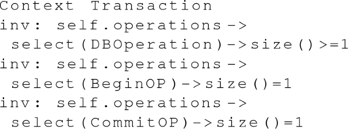
A \(<<\)Transaction\(>>\) must have one \(<<\)BeginOP\(>>\), one \(<<\)CommitOP\(>>\), and at least one \(<<\)DBOperation\(>>\).
-
2.
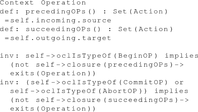
\(<<\)BeginOP\(>>\) marks the start of the transaction. \(<<\)CommitOP\(>>\) and \(<<\)AbortOP\(>>\) mark the end of the transaction. No \(<<\)Operation\(>>\) occurs before a \(<<\)BeginOP\(>>\), or after a \(<<\)CommitOP\(>>\) or an \(<<\)AbortOP\(>>\).
-
3.
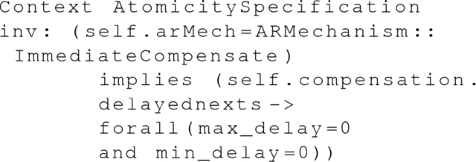
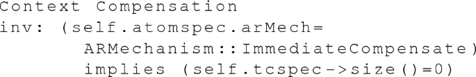
If ImmediateCompensate is selected as the AR, the compensate transaction is executed by the DBMS with no delays between its operations. Therefore, in this case, the max_delay and min_delay values of every \(<<\)DelayedNext\(>>\) edge in the \(<<\)Compensation\(>>\) transaction are 0.
-
4.
Immediate compensation transactions are always executed immediately by the DBMS after abortion. Therefore, they do not have \(<<\)TemporalCorrectnessSpecification\(>>\).
-
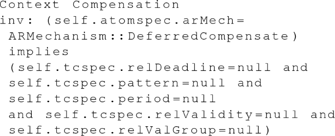
5.
For deferred compensation transactions, the only meaningful value in its \(<<\)TemporalCorrectnessSpecification\(>>\) is priority.
-
6.
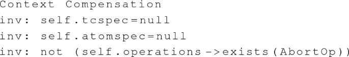
Since cascade abortion introduces high unpredictability and is hence not desired in real-time systems, we assume that compensation transactions do not have user abort operations, and do not get recovered after system abortion. Therefore, a \(<<\)Compensation\(>>\) does not have \(<<\)AbortOp\(>>\), \(<<\)AtomicitySpecification\(>>\), or \(<<\)TemporalCorrectnessSpecification\(>>\).
-
7.
The execTime and absValidity values of every \(<<\)Operation\(>>\) in the \(<<\)IsolationPhenomenon\(>>\) are set to 0.

-
8.
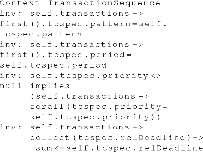
Since the start of the first sub-transaction also marks the start of its containing transaction sequence, the first \(<<\)Transaction\(>>\) has the same pattern and period attributes as its corresponding \(<<\)TransactionSequence\(>>\). Since the other sub-transactions are started by the termination of their previous counterparts, their patterns and periods may remain unspecified and can be derived later. If the \(<<\)TransactionSequence\(>>\)’s priority is specified, all \(<<\)Transactions\(>>\) inherit this priority value. The sum of the relative deadlines of all \(<<\)Transactions\(>>\) must be smaller than or equal to the relative deadline of the \(<<\)TransactionSequence\(>>\).
-
9.
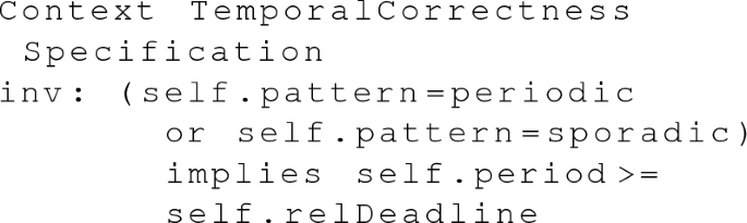
For a periodic or sporadic \(<<\)Transaction\(>>\) or \(<<\)TransactionSequence\(>>\), its period value should be no smaller than its relative deadline. This rule eliminates the following non-schedulable and undesirable execution from early design: A transaction instance is started even before a previous instance, which is known likely to still be in execution.


4 UPPCART framework
In this section, we extend our UPPCART (UPPaal for Concurrent Atomic Real-time Transactions) framework, for pattern-based formal modeling of real-time transactions with concurrency control and abort recovery in UPPAAL TA.
Our UPPCART framework, first proposed in our previous work [8], models the transactions, together with the CC algorithm and the AR mechanisms, as a network of UPPAAL TA. Denoted as N, the NTA of the modeled real-time transactions is defined as follows:
where \(W_{1}\), ..., \(W_{n}\) are work unit automata of transactions \(T_{1}\), ..., \(T_{n}\), respectively. They also model the work unit’s interaction with the transaction manager with respect to concurrency control and abort recovery. \(A_{CCManager}\) is the CCManager automaton that models the CC algorithm, and interacts with the work unit TA. \(A_{ATManager}\) is the ATManager automaton that models the atomicity controller of recovery mechanisms upon abort of transactions. \(O_{1}\), ..., \(O_{k}\) are IsolationObserver automata that observe the phenomena to be precluded by isolation, by monitoring the behaviors of the work unit automata. When a work unit automaton performs a particular sequence of transitions representing a phenomenon, the corresponding IsolationObserver is notified and moves to a state indicating this occurrence. \(D_{1}\), ..., \(D_{m}\) are data automata for the data with temporal validity constraints. \(S_{1}\), ..., \(S_{l}\) are automata for transaction sequences.
For each type of the aforementioned TA in N, we propose a set of parameterized patterns and connectors for the pattern-based construction. In the following, we propose a definition of pattern-based construction, followed by the detailed patterns for UPPCART in the next subsections.
A parameterized pattern (PP) of TA is a reusable structure that models a repetitive behavior or property. Formally, we defined a parameterized pattern as follows:
where \(\mathbf{P} \) is a set of parameters \((p1, \, p2, \, ...)\) that appear in the tuple \((L_{pp}, L_{pinit}, X_{pp}, V_{pp}, I_{pp}, Act_{pp}, E_{pp})\), and \(\mathbf{F} \) is a set of function signatures that appear in \(E_{pp}\).
A parameterized connector (PCon) is a structure that connects two parameterized patterns. Formally, a parameterized connector connecting parameterized patterns \(PP_i\) and \(PP_j\) is defined as follows:
A parameterized pattern can be constructed from sub-patterns and the connectors connecting them, as the unions of their locations, variables, invariants, edges, actions, and parameters.
The instantiation of PP assigns the parameters in \(\mathbf{P} \) with actual values, and provides the functions in \(\mathbf{F} \) with implementations. Using “\(p=v\)” to denote the assignment of parameter p with value v, we define the instantiated pattern as:
Similarly, the instantiation of \(Con_{i, j}\) assigns the parameters in P with actual values:
which is a set of edges of a TA.
Given a TA \(A=(L, l_0, X, V, I, Act, E)\), a set of instantiated patterns PI, and a set of instantiated connectors CON, A is a pattern-based construction from PI and CON, iff:
-
\(L=\bigcup _{PI_i\in \mathbf{PI} }L_{pi\_i}\),
-
\(\bigcup _{PI_i\in \mathbf{PI} }L_{init\_i} = \{l_0\}\),
-
\(X=\bigcup _{PI_i\in \mathbf{PI} }X_{pi\_i} \bigcup _{Con_j\in \mathbf{CON} }X_{con\_j}\),
-
\(V=\bigcup _{PI_i\in \mathbf{PI} }V_{pi\_i} \bigcup _{Con_j\in \mathbf{CON} }V_{con\_j}\),
-
\(Act=\bigcup _{PI_i\in \mathbf{PI} }Act_{pi\_i} \bigcup _{Con_j\in \mathbf{CON} }Act_{con\_j}\),
-
\(E=\bigcup _{PI_i\in \mathbf{PI} }E_{pi\_i} \bigcup \mathbf{CON} \),
which means that the locations, variables, actions and edges of A are the unions of the respective counterparts in the component instantiated patterns and connectors. We denote it as \(A=\dot{\bigcup }(\mathbf{PI} , \mathbf{CON} )\).
For the convenience of later presentations, we call a pattern a skeleton of TA A, if \(L_{init}\ne \emptyset \) .
4.1 Patterns and connectors for modeling work units
In the following subsections, we introduce the UPPCART patterns and connectors for each automaton within the parallel composition in Eq. 1, in the order of the work unit automaton W, the transaction sequence automaton S, CCManager automaton \(A_{CCManager}\), ATManager automaton \(A_{ATManager}\), IsolationObserver O, and data automaton D.

Work unit skeleton (WUS) for a generic transaction \(T_i\) [8]
4.1.1 Work unit skeleton (WUS)
A work unit (WU) automaton models the work unit of a transaction and its interaction with the CC and atomicity managers. A WU skeleton (WUS), as shown in Fig. 4, is a parameterized pattern that consists of the common variables, locations and edges of a WU automaton. Formally, WUS is defined as follows:
The locations \(L_{wus}\) and edges \(E_{wus}\) are shown in Fig. 4, in which \(L_{wusinit}\) is the location initial. The parameters \(\mathbf{P} _{wus}\), clock variables \(X_{wus}\), discrete variables \(V_{wus}\), as well as functions \(\mathbf{F} _{wus}\), are listed in Table 1. In Fig. 4, the automaton starts from the initial location, initializes the transaction with the specified id ti and priority p using function initialize(ti, p), and moves to the location ready. Upon receiving the start_trans[ti] message, it moves to the location trans_started, which represents the begin of the transaction, and resets clock variable tc. The location trans_committed indicates the committed state of the transaction. Between trans_started and trans_committed are a set of connected instantiated patterns that model the database and transaction management operations, and delays between the operations. If the value of tc is greater than the specified DEADLINE, the automaton moves to the location miss_deadline, indicating a deadline miss. Otherwise, it waits until the specified PERIOD has been reached, and moves to begin for the next activation. The location trans_aborted represents the aborted state of the transaction. If the value of tr is greater than the specified RECOVERY_DEADLINE, timeliness is breached, and the WU automaton moves to miss_deadline.

Operation Pattern (OP) [8]
4.1.2 Operation-CC, Locking and Unlocking Patterns, and their Connectors
We define patterns to model the begin, commit, read and write operations in each work unit. Since a transaction may interact with the CC manager according to the specific CC algorithm during the operations, our operation patterns also comprises CC-related activities such as the locking and unlocking activities. The pattern for modeling basic operations, the operation pattern (OP), is presented in Fig. 5. The modeling elements are listed in Table 2. In OP, we model the scheduling policy using three functions, namely, enq_sch(ti), deq_sch(ti) and sch(). After the start_operation location, the enq_sch(ti) function is called, which pushes the transaction into the scheduling queue. On the edges from the location check_sched, the function sch() checks whether the transaction is the next one to be executed. If yes, the automaton moves to do_operation, representing the execution of the operation; otherwise, the automaton waits at location wait, until the CPU is released by the occupying transaction or the RTDBMS, indicated via the signal in the cpu_free channel. The automaton may stay at do_operation for at most WCRT_op time units, and at least BCRT_op time units, which represent the longest and shortest time to complete the operation. Upon the completion of the operation, a signal is sent to the IsolationObservers via channel notify_op[ti]. Before reaching finish_operation, the CPU is set to be free, and the transaction is removed from the scheduling queue by the function deq_sch(ti). As an example, the corresponding functions for a priority-based scheduling policy is listed in Listing 1.

According to the selected CC algorithm, the transaction needs to lock and unlock data, before or after the operations. This is modeled by the Locking Pattern (LP, Fig. 6) and Unlocking Pattern (UP, Fig. 7), which are composed with the operation patterns. The locations and edges are presented in the figures, while the parameters, variables and functions are listed in Table 2. In the locking pattern, the automaton sends a request to the CCManager via channel locktype[ti][di], in which “locktype” is parameterized for the particular type of lock, such as a readlock, specified by the CC algorithm. The automaton then either moves to location finish_locking, if it is granted by CCManager via channel grant[ti][di]; or releases CPU and gets blocked at location wait_for_lock, until CCManager grants it later. In the Unlocking pattern, the automaton sends the request via channel unlock[ti][di], which is received and processed by the CCManager. A database operation may lock (or unlock) several data items altogether, depending on the CC algorithm. The combination of multiple lock/unlocks are modeled by the connectors. The connector connecting two Locking patterns is defined as \(Con(LP_i, LP_j)\) in Table 3, and the connector connecting two unlocking patterns is defined as \(Con(UP_i, UP_j)\) in Table 3.
The composition of LP and UP with OP is illustrated in Fig. 8, which forms the Operation-CC Pattern (OCCP). Formally, OCCP is defined as follows:
in which LP, OP and UP are previously defined sets of locking, operation and unlocking patterns, respectively. The set of connectors is defined as:
\(Con(OP, LP')\) is a connector that connects an OP with a group of LP, as defined in Table 3, in which \(LP'\) is a pattern composed of a set of LP, starting with \(LP_i\) and ending with \(LP_j\). \(Con(OP, UP')\) is a connector that connects an OP with a group of UP, as defined in Table 3, in which \(UP'\) is a pattern composed of a set of UP, starting with \(UP_i\) and ending with \(UP_j\). Con(Begin, WUS) and Con(Commit, WUS) are connectors that connect the begin OP and commit OP to the work unit skeleton WUS, also defined in Table 3.

Locking Pattern (LP) [8]

Unlocking Pattern (UP) [8]

Operation-CC Pattern (OCCP) [8]
4.1.3 Delay Pattern and its Connector
The delay pattern (DP) in Fig 9 models the delays between operations, formally defined as follows:
which contains one location and its invariant as shown in Fig 9, and a parameter MAX_delay. The automaton may stay at location delay for at most MAX_delay time units.

Delay Pattern (DP) [8]
Assuming that \(OP_i\) and \(OP_j\) model the operations before and after a delay modeled by DP, respectively, the connectors to connect \(OP_i\) and DP is defined as \(Con(OP_i, DP)\) in Table 3. The connector for connecting DP with \(OP_j\) is defined as \(Con(DP, OP_j)\) in Table 3, in which MIN_delay is a parameter and denotes the lower bound of the delay.
4.1.4 Abort and Recovery Patterns, and their Connectors
The abort recovery mechanisms are modeled by the RollbackImComp Pattern (RIP, Fig. 10), and the DeferredComp Pattern (DCP, Fig. 11), respectively, which are composed into the work unit automata. The former (RIP) models the rollback and immediate compensation mechanisms, which are executions of series of operations by the DBMS immediately after the abort. In case of rollback, the recovery operations redo the write operations that have been completed by the aborted transaction. In case of immediate compensation, the operations are specified for the transaction explicitly. The latter (DCP) models the deferred compensation mechanism, which executes a separate transaction for compensation. The locations and edges are shown in the figures, while parameters, variables and functions are listed in Table 4.

RollbackImComp Pattern (RIP) [8]

DeferredComp Pattern (DCP) [8]
In the RIP pattern (Fig. 10), each operation is represented by a location op_n, at which the automaton may stay for at most (least) WCRT_opn (BCRT_opn) time units. When all operations are completed, the completion of recovery is reported to the ATManager via channel report_abort[ti], removes the transaction from the scheduling queue by function deq_sch(ti), and notifies the IsolationObserver via channel notify_abort[ti].
In case of deferred compensation, a compensating transaction is modeled as a separate work unit, using the work unit skeleton and the operation patterns. The DeferredComp pattern (Fig. 11) starts the compensation transaction via the channel start_trans[ci], where ci is the id of the compensating transaction. The work unit automaton then immediately reports to ATManager and removes the transaction from the scheduling queue. When the compensating transaction ci has committed, the work unit automaton receives the notification of ci, and notifies that transaction is aborted and recovered via channel notify_abort[ti].
The above two recovery patterns are composed into a work unit skeleton via the UserAbort Pattern, if they model the recovery for user abort; or via the System Abort Connectors, if the recovery is performed for system abort.
4.1.5 UserAbort Pattern (UAP)
This pattern is defined as a composition of a recovery pattern (RIP or DCP) with a UserAbortOp (UAO) pattern as shown in Fig. 12. When the work unit is scheduled as the next one to be executed, according to function sch(ti), it issues the abort request to ATManager via channel user_abort[ti]. After it gets the permission from ATManager via channel abort_trans[ti], the automaton proceeds to the corresponding abort recovery pattern. When the recovery is completed, the automaton sets the CPU to be free. Formally, UAP is defined as follows:
Here, the locations and edges of UAO are defined in Fig. 12, while the parameters, variables and functions are listed in Table 4. \(\mathbf{CON} _{uap}\) contains connectors Con(UAO, RIP) and Con(UAO, DCP), as defined in Table 3.
The UAP can be composed with the delay pattern representing the delay before the user abort operation, using the connector Con(DP, UAP) in Table 3. The UAP is composed with the work unit skeleton using the connector Con(UAP, WUS) in Table 3.
4.1.6 System Abort Connectors
System abort and its consequent recovery activities may take place either during one operation, or between the execution of two operations. We define the following connectors to model both behaviors. For the system abortion that occurs within one operation, we define Con(OCCP, RIP) and Con(OCCP, DCP) that compose an instantiated Operation-CC pattern with a RollbackImComp pattern or a DeferredComp pattern, respectively, as illustrated in Fig. 13. When the OCCP receives a signal via channel abort_trans[ti] from the ATManager, it moves to the corresponding abort recovery patterns. The connectors are defined as Con(OCCP, RIP) and Con(OCCP, DCP), respectively, in Table 3.

UserAbort Pattern (UAP) [8]

System Abort Connector Con(OCCP, RIP) and Con(OCCP, DCP) [8]
For system aborts that occur between operations, we define the following connectors Con(DP, RIP) and Con(DP, DCP) in Table 3, which connect a Delay pattern with a RollbackImComp pattern or a DeferredComp pattern respectively.
In addition, to connect the recovery patterns with the work unit skeleton, we define connectors Con(RIP, WUS), and Con(DCP, WUS), respectively, in Table 3.
4.1.7 Pattern-based Construction of a WU Automaton
With these definitions of patterns and connectors, a work unit automaton W is a pattern-based construction, as follows:
in which,
-
WUS is an instantiated WUS for the basic structure of W, defined in Equation 6;
-
OCCP is a set of instantiated OCCP, defined in Equation 7, each representing a begin, commit, read or write operation;
-
UAP is a set of instantiated UAP, defined in Equation 10, each representing a user abort operation;
-
DP is a set of instantiated DP, defined in Equation 9, each representing a delay between two operations;
-
CON is a set of instantiated connectors defined in Table 3: Con(Begin, WUS), Con(Commit, WUS), Con(UAP, WUS), Con(DP, OCCP), \(Con(OCCP, DP)\), for each OCCP, DP and UAP.
The pattern-based construction of a WU automaton is illustrated in Fig. 14.
4.2 Patterns and Connectors for Modeling TransactionSequence
The modeling units in this subsection model the basic structure of a TransactionSequence, as well as the interactions between the TransactionSequence and its sub-transactions.

Illustration of pattern-based construction of a WU automaton

TransactionSequence Skeleton (TSS)
4.2.1 TransactionSequence Skeleton (TSS)
The skeleton of a TransactionSequence, presented in Fig. 15, resembles the work unit skeleton of a transaction, in which its basic locations represent the ready, start, termination and deadline-missing states, respectively. Formally, TSS is defined as follows:
in which the parameters, variables and functions are defined in Table 5. A clock variable ts keeps track of the time spent by the sequence. If the value of ts exceeds the specified deadline, the automaton will reach the miss_deadline location.

Sequence Sub-transaction Pattern (SSP)
4.2.2 Sequence Sub-transaction Pattern (SSP)
A TransactionSequence skeleton incorporates a series of instantiated Sequence Sub-transaction Patterns (SSP), shown in Fig. 16, which models the behavior of starting a sub-transaction and waiting for its termination. SSP is formally defined as follows:
where the locations and edges are defined as shown in Fig. 16, and \(\mathbf{P} _{ssp}\) contains a parameter ti that represents a sub-transaction. The TransactionSequence automaton starts a sub-transaction ti by sending a message via the start_trans[ti] channel, which is received by the WU automaton of transaction ti. Then the TransactionSequence automaton waits for the broadcast signals of either commitment or abortion of ti.
4.2.3 TransactionSequence Connectors
To connect a TransactionSequence with its sub-transactions, we define the following connectors in Table 3: \(Con(TSS, SSP_i)\), and \(Con(SSP_j, TSS)\).
We also define the following connectors to connect two sub-transaction with delay between them: \(Con(SSP_i, DP)\) and \(Con(DP, SSP_j)\) in Table 3 in which DP is a delay pattern.
With these definitions of patterns and connectors, we define a TransactionSequence automaton S as the following pattern-based construction:
in which,
-
TSS is an instantiated TSS, defined in Equation 12, for the basic structure of the sequence automaton;
-
SSP a set of instantiated SSP, defined in Equation 13, each representing the control of a sub-transaction;
-
DP is a set of instantiated DP, defined in Equation 9, each representing a delay between two sub-transactions;
-
CON is a set of the following instantiated connectors defined in Table 3: Con(TSS, SSP), Con(SSP, TSS), Con(DP, SSP), Con(SSP, DP), for each SSP and DP.

CCManager Skeleton (CCS) [8]
4.3 CCManager Skeleton (CCS)
The CCManager skeleton, presented in Fig. 17, provides a common structure for modeling various CC algorithms, and the interaction with the transactions and the atomicity manager. Formally, CCS is defined as follows:
in which the locations and edges are defined as shown in Fig. 17. Table 6 lists the parameters and variables, as well as functions to encode the resolution policy of a CC algorithm. In this skeleton, the CCManager calls satisfyPolicy() when it receives a locking request, in order to decide whether the requester should be granted with the lock. If the function returns true, and no other transactions should be aborted, as suggested by needAbort(), the requester is granted with the lock. If any transactions need to be aborted due to concurrency conflicts, CCManager sends a signal to ATManager via channel cc_conf, and waits until all abort and recovery have been processed, before it grants the lock to the requester. On the other hand, if satisfyPolicy() returns false, the requester either gets aborted, decided by needAbort() according to the CC algorithm, or gets blocked and has to wait.

ATManager Skeleton (ATS) [8]
In case the CCManager receives an unlocking request, it updates the status of the transaction and the locks, and grants locks to all legitimated blocked transactions, decided by the getNext() function.
Automaton \(A_{CCManager}\) is then constructed by instantiating the CCManager skeleton, according to the selected CC algorithm. For instance, Listing 2 shows the function satisfyPolicy() of the CCManager that models the conflict detection of the 2PL-HP algorithm.

4.4 ATManager Skeleton (ATS)
We separate the atomicity control model into an ATManager automaton, and the abort recovery parts in work unit automata. The ATManager models the decisions on aborted transactions upon errors, conflicts or user’s instructions. The work unit automata include the instantiated abort recovery patterns that model the selected mechanisms for the specific transactions. We distinguish two types of abort, which are user abort that is issued by a client using an abort operation deliberately, and system abort that occurs due to internal conflicts and system failures, such as CC conflicts.
Our ATManager skeleton provides a common structure for modeling the atomicity manager. Formally, ATS is defined as follows:
in which the locations and edges are defined in Fig. 18, while the parameters, variables and functions are listed in Table 7. The ATManager may receive user abort requests via user_abort[i] channel, or system abort due to CC via cc_conf channel from CCManager. Other types of errors, such as communication errors, can be modeled in a similar way. The function getAbort() specifies the logic to decide the transaction to be aborted. The automaton then sends the abort signal to the corresponding work unit automaton via channel abort_trans[abort_id], and waits until the abort is done by the work unit automaton. ATManager then updates the status and locks of transactions and data using the function updateAbort(), and checks if more transactions need to be aborted. The construction of automaton \(A_{ATManager}\) is achieved by instantiating this ATManager Skeleton.
4.5 IsolationObserver Skeleton (IOS)
The skeleton for an IsolationObserver is shown in Fig. 19. Formally, IOS is defined as follows:
in which the locations and edges are defined in Fig. 19. The parameters include transaction ids ti and tm, as well as data ids dj and dn. Each IsolationObserver observes a specified sequence of operations, by accepting the corresponding notification messages from the work unit automata via the notify_op[ti][di] channel when an operation is completed. If the monitored sequence indicating the phenomenon occurs, the automaton moves to the isolation_phenomenon location.
4.6 Data Skeleton (DS)
Fig. 20 presents the skeleton of data. Formally, DS is defined as follows:
in which the locations and edges are defined in Fig. 20. The parameters include a list of transaction ids trans_t, as well as data id di. The clock variable age is reset every time a write operation is performed on the data. The value of age hence represents how old the data is since the last update.

IsolationObserver Skeleton (IOS) [8]

Data Skeleton (DS) [8]
4.7 Summary of Modeling
Given a set of transactions and the selected CC and AR mechanisms, the UPPCART model of the RTDBMS can be created by the parallel composition of its component TA, which are constructed via the pattern-based construction by instantiating our proposed patterns and connectors. Formally, the pattern-based construction of the RTDBMS is defined as follows:
in which:
-
\(W_i:{:=}\dot{\bigcup }(\{WUS_i\} \bigcup \mathbf{OCCP} _i\bigcup \mathbf{UAP} _i\bigcup \mathbf{DP} _i, \mathbf{CON} _i),\)
-
\(A_{CCManager} :{:=} \dot{\bigcup }(\{CCS\}, \emptyset ),\)
-
\(A_{ATManager} :{:=} \dot{\bigcup }(\{ATS\}, \emptyset ),\)
-
\(O_i :{:=} \dot{\bigcup }(\{IOS_i\}, \emptyset ),\)
-
\(D_i :{:=} \dot{\bigcup }(\{DS_i\}, \emptyset ),\)
-
\(S_i:{:=}\dot{\bigcup }(\{TSS_i\}\bigcup \mathbf{SSP} _i\bigcup \mathbf{DP} _i, \mathbf{CON} _i).\)
The pattern-based construction allows large parts of existing models to be reused, in case a different CC or AR is selected, and the models need to be updated. An example is presented in our previous work [21], which demonstrates the easy adjustments when different CC algorithms are selected for the same sets of transactions and data.
It is possible to extend UPPCART to model more varieties of transaction management and behaviors. For instance, one can also add a TA to the parallel composition, to model the dispatching pattern of transactions from the clients. This TA sends signals via the start_trans[i] channel to each \(W_{i}\), with a specific order and predefined intervals. It may even receive the notify_commit[i] signals from \(W_{i}\), such that the end-to-end deadline of a sequence of transactions can be monitored.
4.8 Verification
With the transactions as well as the atomicity and concurrency control mechanisms modeled in UPPAAL TA, we are able to formally verify the atomicity, isolation and temporal correctness properties using UPPAAL Model Checker.
Table 8 lists the patterns to formalize the properties in UPPAAL queries. Among them, atomicity is formalized as a liveness property, that the automaton \(A_i\) representing transaction \(T_i\) eventually reaches the dedicated trans_rollback or trans_compensated location if the abort_id equals i. Isolation and temporal correctness are formalized as invariance properties. The isolation property is specified as the isolation_phenomenon locations are not reachable. The timeliness property is formalized as the miss_deadline location of the analyzed \(T_i\) is not reachable, while temporal validity properties are formalized as the states where the ages of data exceed their thresholds are never reachable.
5 From UTRAN to UPPCART
We provide a translational semantics from UTRAN to UPPCART, in order to bridge the gap between the high-level description of transactions and the verifiable models for reasoning about the transaction properties. In this way, the formal semantics of UTRAN is defined using UPPAAL TA, which also lays the foundation of automated transformation from UTRAN to UPPCART models. In this section, we first introduce the semantic definitions of UTRAN (Section 5.1), followed by the tool automation for the transformation (Section 5.2).
5.1 Translational Semantics of UTRAN
We encode the formal semantics of UTRAN in terms of UPPCART as follows:
Definition 1
An \(<<\)RTDBMSScope\(>>\) in UTRAN is formally defined as an UPPCART NTA \(N_{RTDBMS}\), whose definition is given in Equation 1.
Definition 2
An \(<<\)IsolationSpecification\(>>\) in the \(<<\)RTDBMSScope\(>>\) is formally defined as \(A_{CCManager}\) and a set of IsolationObservers in \(N_{RTDBMS}\). The \(A_{CCManager}\) is an instantiation of the CCManager skeleton with the selected CC algorithm, that is, the value of CCAlgorithm in the \(<<\)IsolationSpecification\(>>\). An \(<<\)IsolationPhenomenon\(>>\) specified in the \(<<\)IsolationSpecification\(>>\) is defined as an instantiated IsolationObserver skeleton.
Definition 3
A \(<<\)Transaction\(>>\) \(T_i\) in the \(<<\)RTDBMSScope\(>>\) is formally defined as a work unit TA \(W_{i}\), according to Equation 11, in the parallel composition of \(N_{RTDBMS}\).
The \(<<\)Operations\(>>\) within a \(<<\)Transaction\(>>\) are defined as follows:
Definition 4
A \(<<\)BeginOp\(>>\), \(<<\)CommitOp\(>>\), \(<<\)ReadOp\(>>\) or \(<<\)WriteOp\(>>\) is formally defined as an instantiated OCCP. The data j read by \(<<\)ReadOP\(>>\) r, with \(r.did == j\) and \(r.absValidity>0\), is defined as a Data automaton \(D_{ij}\) by instantiating the Data skeleton.
Depending on the value of CCAlgorithm in the \(<<\)IsolationSpecification\(>>\), the OCCP is defined by composing an OP (operation), with zero or more LP (locking) or UP (unlocking).
For instance, if \(CCAlgorithm \in \{2PL{\text{- }}HP, R2PL\}\), the operations with CC are defined as follows:
-
For the \(<<\)BeginOP\(>>\), \(OCCP_{begin}:{:=}\dot{\bigcup }(\{OP_{begin}\}, \emptyset )\).
-
For each \(<<\)ReadOP\(>>\) r, with \(r.tid == i\) and \(r.did == j\), \(OCCP_i:{:=}\dot{\bigcup }(\{OP_i, LP_i\}, \{Con(OP_i, LP_i)\})\), in which the parameter locktype in \(LP_i\) is readlock.
-
For each \(<<\)WriteOP\(>>\) w, with \(w.tid == i\) and \(w.did == j\), \(OCCP_i:{:=}\dot{\bigcup }(\{OP_i, LP_i\}, \{Con(OP_i, LP_i)\})\), in which the parameter locktype in \(LP_i\) is writelock.
-
For the \(<<\)CommitOP\(>>\), \(OCCP_{commit}:{:=}\dot{\bigcup }(\{OP_{commit} \}\bigcup UP', \{Con(OP_{commit}, UP')\})\), in which \(UP'\) is a pattern composed of a set of unlocking patterns for all data read or written by the transaction.
If \(CCAlgorithm \in \{ShortReadlock\}\), the operations with CC are defined as follows:
-
For the \(<<\)BeginOP\(>>\), \(OCCP_{begin}:{:=}\dot{\bigcup }(\{OP_{begin}\}, \emptyset )\).
-
For each \(<<\)ReadOP\(>>\) r, with \(r.tid == i\) and \(r.did == j\), \(OCCP_i:{:=}\dot{\bigcup }(\{OP_i, LP_i, UP_i\}, \{Con(OP_i, LP_i), Con(OP_i, UP_i)\})\), in which the parameter locktype in \(LP_i\) is readlock.
-
For each \(<<\)WriteOP\(>>\) w, with \(w.tid == i\) and \(w.did == j\), \(OCCP_i:{:=}\dot{\bigcup }(\{OP_i, LP_i\}, \{Con(OP_i, LP_i)\})\), in which the parameter locktype in \(LP_i\) is writelock.
-
For the \(<<\)CommitOP\(>>\), \(OCCP_{commit}:{:=}\dot{\bigcup }(\{OP_{commit} \}\bigcup UP', \{Con(OP_{commit}, UP')\})\), in which \(UP'\) is a pattern composed of a set of unlocking patterns for all data writen by the transaction.
Definition 5
A \(<<\)DelayedNext\(>>\) edge is formally defined as an instantiated DP, together with connectors \(Con(OCCP_i, DP)\) and Con(DP, \( OCCP_j)\), where \(OCCP_i\) and \(OCCP_j\) are the source and target \(<<\)Operation\(>>\) of the \(<<\)DelayedNext\(>>\), respectively.
Definition 6
An \(<<\)AtomicitySpecification\(>>\) associated with the \(<<\)Transaction\(>>\) is formally defined as a construction of patterns and connectors, depending on the values in the specification. We define a Con(OCCP, RIP) for each OCCP, if \(arMech \in \{Rollback, ImmediateCompensate\}\); or a Con(OCCP, DCP) for each OCCP, if \(arMech \in \{DeferredCompen {\text{- }}sate\}\). For each DP, we define a \(Con(DP, RIP)\) or a Con (DP, DCP).
Definition 7
Each \(<<\)AbortOp\(>>\) is formally defined as an instantiated UAP, which is composed with a Con(OCCP, RIP) or a \(Con(OCCP, DCP)\), depending on the value of attribute arMech in the associated \(<<\)AtomicitySpecification\(>>\).
Definition 8
A \(<<\)TransactionSequence\(>>\) \(Seq_i\) is formally defined as a TA \(S_i\), according to Equation 14, whose construction elements are defined by the following:
-
1.
Each \(<<\)Transaction\(>>\) in the sequence is defined as an instantiated Sequence Sub-transaction Pattern (SSP), together with the connectors Con(TSS, SSP) and Con( SSP, TSS).
-
2.
Each \(<<\)DelayedNext\(>>\) between the \(<<\)Transactions\(>>\) is defined as an instantiated DP, as well as instantiated connectors Con(DP, SSP) and Con(SSP, DP).
5.2 Automated Transformation
Automated transformation from UTRAN specifications to UPPCART models can reduce the efforts of system designers by shielding them from the under-the-hood formalism. In this section, we developed a Java-based tool prototype, called U\(^{2}-Transformer\) [12], which provides automated transformation based on the previously mentioned mapping.
U\(^{2}\)Transformer accepts a system model defined in UML with the UTRAN profile, created in common UML editors including Eclipse Papyrus modeling environmentFootnote 3 and IBM Rational Software Architect (RSA) environmentFootnote 4, in their respective XML format. The tool parses the UTRAN specifications and returns the XML-format UPPCART models for the UPPAAL tool. More implementation details of the tool can be referred to in our extended report [22].
5.3 Validation of U\(^{2}\)Transformer
As the first step of validation, we create a series of unit test cases to test the individual mappings in Section 5.1. They generate pieces of UPPCART models corresponding to the selected subsets of UTRAN concepts. These cases include transformation of single transactions with only one type of the properties, as well as sequences of transactions with multiple properties. The generated models are manually checked for their correctness. The test units are written using the JUnit framework, and are included in the source files of the tool.
We also apply a common approach to test model transformation, that is, to compare the automatically generated model with an expected output model [23]. We use the example UTRAN specification and its manually-generated corresponding UPPCART model from our previous work [8] as a reference for the validation.
The UTRAN example in [8] specifies the transactions managing the configuration data and mission status of an autonomous wheel loader. It involves three ordinary transactions, one compensation transaction, five data objects, as well as the atomicity, isolation and temporal correctness specifications. The UPPCART model is created manually by the authors, which is a network of UPPAAL TA that conforms to Equation 1. We use the same UTRAN specification as the input of U\(^{2}\)Transformer, and run the translation. The generated UPPCART model contains the same elements (e.g., individual automata and global variables) as the manually created model, and satisfy the same atomicity, isolation and temporal correctness properties.
6 Case Study
In this section, we demonstrate UTRAN, UPPCART and the tool-supported transformation, via the specification and verification of a transaction-based system.
Autonomous construction vehicles such as wheel loaders and excavators are considered as a promising trend to reduce costs and avoid safety hazards in construction and mining sites. In this case study, we consider a quarry where raw materials (e.g., iron ores) are mined by excavators, and transported by a group of wheel loaders to crushers deployed on the site. A mission is decided for each wheel loader and excavator, which follows a designed path in order to complete its job, such as transportation of materials, and maintenance activities, such as charging the battery. In order to ensure safety while maintaining productivity, we design a two-layer collision avoidance system to prevent collisions between vehicles achieved by the global collision avoidance layer, as well as with obstacles such as rocks and holes, achieved by the local collision avoidance layer. The functionalities of both layers rely on the data management and transaction control provided by their DBMS. In the following subsections, we present the design of the DBMS in these two layers, as well as the verification of the crucial temporal and logical properties using our proposed framework and tool, respectively.
6.1 Global Collision Avoidance Layer

Map and paths of vehicles in our case study

Illustration of collision avoidance through transactions and CC
The center of the global collision avoidance layer is a global DBMS that stores the map of the quarry, which is divided into smaller cells of a grid. The mission of a vehicle is represented as a sequence of cells that it should visit. Fig. 21 presents the map of the quarry in our case study. Three wheel loaders are deployed at Cells 7, 10 and 17, whose plans are determined to carry materials to the crushers at Cells 9 and 18, respectively. On the way back from the crushers, some of the wheel loaders are scheduled to refuel at the charging stations at Cell 12, as shown in their paths respectively. An excavator digs the ores at Cell 11. From time to time, the excavator also needs to charge at Cell 12. As illustrated in the figure, the vehicles not only share the crushers and the power stations, but their paths also overlap in multiple cells.
In order to avoid collision with each other, the vehicles are not allowed to operate in the same cell simultaneously. To achieve optimal productivity, each wheel loader is scheduled to operate its mission with a specific period, and is expected to finish by a given deadline. In addition, since there are more wheel loaders than excavators, it is further required to allow the excavator to be charged whenever necessary for better productivity. In other words, the excavator should be prioritized to use the charging station.
We achieve global collision avoidance by leveraging concurrency control of the DBMS to prevent multiple vehicles operating in the same cell simultaneously. The key idea is to let a vehicle lock the cell before entering it, and unlock it when the vehicle is about to leave the cell. As illustrated in Fig. 22, the entire path of a vehicle is modeled as transaction sequence, while the activity of passing an individual cell, including the performed job in it, is modeled as a transaction. Before entering a cell, a vehicle starts a transaction and performs a write operation on the cell data, which results in a lock on the cell. Before the vehicle leaves the cell, it commits the transaction, which releases the lock and allows other vehicles to enter this cell. We assume the committing vehicle is in full stop before entering the next cell. Therefore, even if another vehicle may enter the unlocked cell before the committing vehicle leaves, these two are not operating their tasks simultaneously, and hence are considered safe. To ensure immediate access of the high-priority vehicle, we apply a priority-based CC (2PL-HP [17]), which aborts the low-priority transaction when two transactions try to lock the same data.

Excerpt of the UTRAN specification for the global layer using the Papyrus tool
Based on this, we identify 4 transaction sequences in the global layer, each for one vehicle in Fig. 21; with a total number of 18 transactions, each controlling one vehicle passing one cell, and 2 compensation transactions re-entering the charging stations. The sequences and transactions are listed in Table 9. For temporal correctness, in this case study we focus on the end-to-end deadlines of the sequences. The isolation constraint imposed by safety requires that two vehicles should not use the same cell, especially the power station, that is, no simultaneous access to Cell 12. In addition, since the excavator has a higher priority, the wheel loaders L1 and L2 may be aborted when they are using the power station. We hence add the atomicity requirement that when charging gets aborted, the vehicle should redo the charging later when the station is free.

Transformation of the UTRAN specification using U\(^{2}\)Transformer

Excerpt of the UPPCART models for S1L1 from the UPPAAL tool
6.1.1 Specification in UTRAN
Fig. 23 presents an excerpt from the Eclipse Papyrus tool that exhibits the specification of transaction sequence S1L1. The sequence contains five \(<<\)Transactions\(>>\). Each \(<<\)Transaction\(>>\) includes three \(<<\)Operations\(>>\): one \(<<\)BeginOP\(>>\), one \(<<\)WriteOP\(>>\) that writes the cell data, and one \(<<\)CommitOP\(>>\). The time to perform the operation in the cell (e.g., digging, cruising, crushing, or charging) is specified as the delay in the \(<<\)DelayedNext\(>>\) edge between the \(<<\)WriteOP\(>>\) and the \(<<\)CommitOP\(>>\). The timing properties of S1L1 are specified in its attached \(<<\)TemporalCorrectnessSpecification\(>>\). \(<<\)Transaction\(>>\) G12 is associated with an \(<<\)AtomicitySpecification\(>>\), which refers to \(<<\)Compensation\(>>\) RedoCharge1 as its deferred compensating transaction. An \(<<\)IsolationPhenomenon\(>>\), E1- L1Conflict, specifies the interleavings that results in the simultaneous access of Cell 12, which should be prevented by the CC. The complete specification can be found in our online repository [12].
6.1.2 Construction of UPPCART models
We applied U\(^{2}\)Transformer to generate UPPCART models. As shown in Fig. 24, we used the command-line interface to specify the Eclipse Papyrus format, the path to the input UTRAN file, and the output path for the generated UPPAAL model. The transformation took 4.097 s.
Figure 25 shows an example of the generated UPPCART model for S1L1, which corresponds to the \(<<\)TransactionSequence\(>>\) S1L1 in Fig. 23. The main structure of this TA is an instantiation of the TransactionSequence Skeleton and represents the basic structure of the sequence S1L1. Its sub-transactions, including G17, G18, G13, G12, and G17_2, are modeled by instantiation of the sub-transaction patterns, respectively.
6.1.3 Optimization
During the simulation and verification of the generated models, we realize that the number of channels is large, which causes very long time for UPPAAL to reach a conclusion. For instance, we have a matrix of channels for write locks, whose number is a multiplication of the number of transactions and the number of data. This contributes greatly to the state space, which results in extremely long verification time. Therefore, we have performed a few optimizations in the TA models. First, we merge the begin operation with the write operation in each sub-transaction. This is because the delays between these two operations are negligible (in milliseconds) compared with the mission time (in hundreds or thousands of seconds). This way, we can reduce the channels related to the begin operations. Second, since within each sequence, only one sub-transaction can be executed at any time, we therefore use the sequence ID to identify its sub-transactions in the channels. This considerably reduces the number of channels without changing the semantics of the models. For instance, the number of channels for write locks is now a multiplication of the number of sequences and the number of data, which is significantly smaller than using separate transaction ID’s. Both the original and the optimized UPPCART models are presented in our online repository [12].
6.1.4 Verification of the global layer
We verify the optimized models against the requirements using the UPPAAL model checker (version 4.1.19). The verification PC is equipped with an Intel i7-4800MQ CPU (2.70 GHz, 8 cores), 16 GB memory, and Ubuntu 16.04 (64-bit). The verification results, presented in Table 10, show that the current design satisfies all imposed requirements.
6.2 Local collision avoidance layer
The local collision avoidance layer allows a vehicle to move around an obstacle in its way, by monitoring the surroundings using a camera, a sensor and a lidar. Timely update and access of the surrounding data, as well as correct reaction to the detection of obstacles, are crucial to the safety of the vehicle. The data and all related transactions are listed in Table 11. In our case, these data are stored in the vehicle’s local DBMS, and updated periodically by transactions UpdateCamera, UpdateSensor, and UpdateLidar respectively. Another transaction MoveVehicle reads these data, and checks if any obstacle occurs. If the path is clear, the vehicle moves forward for a period of time, and commits the transaction. If an obstacle occurs, the MoveVehicle transaction is aborted, after which a compensation AvoidObstacle is started to move around the obstacle, and updates a log with the obstacle position for the future updates of vehicle paths.

Excerpt of the UTRAN specification for the local layer using the Papyrus tool
Similar to the design of the global layer, we specify the local layer in UTRAN, as presented in Fig. 26. Each transaction in Table 11 is specified as an activity stereotyped with \(<<\)Transaction\(>>\) (or \(<<\)Compensation\(>>\) for AvoidObstacle), with their properties specified in the attached \(<<\)TemporalCorrectnessSpecification\(>>\) and \(<<\)AtomicitySpecification\(>>\). We generate the UPPAAL models from this UTRAN specification using our tool. The complete specifications and the TA models are presented in our online repository [12].
The verification results of the local collision avoidance layer are listed in Table 12. The desired atomicity and temporal correctness properties are satisfied by the current design, according to the verification results.
Since all desired requirements have been satisfied, no trade-offs among the properties are necessary in our current design. However, in case any violation was detected by the verification, indicating conflicts among the properties, the designer would need to revise the design with trade-off decisions. Such trade-offs may involve adjustments in the selected CC, AR and scheduling mechanisms, as well as in the variants of the properties. The revised specifications are then formalized and checked as mentioned above. Such revising-and-model-checking iterations continue until we reach a design that satisfies all desired properties.
7 Related work
Researchers have made a number of efforts in the specification of transaction-based systems and their properties. Among them, ASSET [24] and KALA [25] specify flexible transaction models with procedural languages, in which operations and AR mechanisms are specified using primitives provided by the languages. ReflecTS [26] allows specification of various ACID properties of flexible transaction models. Compared to these works, our supports specification of temporal correctness for transactions and transaction sequences, and the selection of CC algorithms. Several high-level description languages opt for extending UML with elements related to the topic. In the real-database profile proposed by Marouane et al. [27], the authors extend MARTE for real-time database systems and incorporate timing properties such as transaction timeliness. However, neither transaction sequence nor atomicity or isolation are their focus. Unified transaction modeling language (UTML) [28] and its extension [29] extend UML for transactions with various selection of the ACID properties. In these works, atomicity and isolation are treated as monolithic properties respectively, rather than a spectrum of variants. Temporal correctness of transactions and transaction sequences is not addressed.
Some influential work include the Business Process Execution Language (BPEL) [30], the Business Process Model and Notation (BPMN) [31], and their extensions. Both BPEL and BPMN are XML-based, high-level description languages for specifying business processes, which can be considered as a flexible transaction model with various atomicity options. Rollback and compensation can be specified at transaction level and for internal activities. Invocation dependencies between transactions are also supported by these languages. Charfi et al. [32] and Sun et al. [33] introduce extra concepts for transactions to BPEL, which allow explicit specification of atomicity policies. Compared with their work, our proposed profile can specify variants of isolation for a group of transactions, as well as timing properties for transactions and transaction sequences. Watahiki et al. [34] propose to strengthen BPMN with temporal constraints, and generate UPPAAL models for verification. Isolation and CC are out of the scope of this framework.
As for formal modeling and analysis of transaction properties, the ACTA framework [35] specifies transaction models in first order logic and allows for formal reasoning. Derks et al. [13] propose to model and verify transactions with atomicity variants in Petri nets. Gallina [7] uses higher-order logic to specify transaction properties, which can be formally analyzed by the Alloy tool. A number of formal languages for transaction models have been discussed by Gallina [7]. However, these frameworks are restricted in the formal specification and analysis of ACID, while timeliness, especially the impact of CC and abort recovery mechanisms on the time, are not included. In a more recent work, Liu et al. [36] model a transaction model using Maude, and analyze only properties regarding logical consistency. Lanotte et al. [37] propose a timed-automata-based language for long running transactions with timing constraints. Committing protocols for atomicity variants can be modeled and analyzed. In contrast to these works, our work provides a formal framework for modeling transactions together with abort recovery and CC mechanisms, in which atomicity, isolation, temporal correctness, as well as their impacts on each other, can be analyzed in a unified framework. Our recent work [38] proposes the UPPCART-SMC framework, which models the transaction system as stochastic timed automata, and applies statistical model checking [39] to analyze the same properties as we do in this paper. Although UPPCART-SMC avoids the state explosion problem and thus can analyze large systems, it only provides probabilistic assurance of the properties. On the contrary, UPPCART in this paper applies exhaustive model checking and provides a formal guarantee of the properties.
Pattern-based techniques have been considered useful in modeling real-time systems with timed automata. Dong et al. [40] propose a set of TA patterns for common timing constraints, such as delay and deadline. Mekki et al. [41] introduce TA observer patterns for time-related requirement in UML statecharts. Étienne André [42] proposes a set of TA observer patterns for timing constraints and behaviors of real-time systems. In our work, we also apply pattern-based techniques to model real-time transactions. We provide a formal definition of patterns and pattern-based modeling in our context. Our patterns are not only used to model time-related behaviors and observe timing properties, but also used to specify transaction management mechanisms and capture data inconsistency.
Researchers have proposed many tool chains for modeling and analyzing various aspects of critical systems, within the model-driven engineering paradigm. Examples include the work of Biehl et al. [43], ViTAL [44] and CHESS [45]. In these tool chains, domain-specific languages are implemented to be applied by users to create system specifications, which are then transformed into formal models for rigorous analysis. Our work shares the same model-driven engineering approach, facilitated with our own language, formal semantics, and transformation.
8 Conclusions and future work
In this paper, we have presented a high-level specification language that extends our previously proposed UTRAN profile. In addition to the specification of transactions with atomicity, isolation and temporal correctness properties, the extended UTRAN profile also supports specification of transaction sequences and their timing constraints. We have also extended our previously proposed UPPCART framework, a pattern-based formal framework that models transactions in UPPAAL timed automata, with counterparts for transaction sequences.
We have proposed a formal definition of pattern-based construction of UPPCART models, based on which we are able to provide a mapping between the UTRAN elements and UPPCART patterns, and automate the transformation from UTRAN to UPPCART. Designers can specify the transactions in UML diagrams with UTRAN using existing UML editors, and transform them into formal models that can be rigorously analyzed by UPPAAL. The automated transformation is supported by our tool U\(^{2}\)Transformer.
We also have performed an industrial use case that involves collision avoidance of autonomous vehicles via transaction management. In the case study, we applied UTRAN to specify the transactions in the system, and transformed them into UPPCART models using U\(^{2}\)Transformer. The desired atomicity, isolation and temporal correctness properties were successfully verified by UPPAAL model checker. A lesson learned from the use case is that, the automatically generated models can be further optimized according to the application semantics. By reducing, for instance, the number of channels, the models may achieve much smaller state space and result in much shorter verification time and lower memory consumption. This is important for large systems since we use exhaustive model checking for the analysis. Such optimization, admittedly, requires knowledge in formal modeling with UPPAAL. Nevertheless, our proposed tool automation greatly reduces the efforts to construct the formal models.
Although only a set of property variants and mechanisms are selected and presented in this paper, our work can be used as a general framework for creating formally assured designs for a wider variety of transaction models applied in data and process management. Both transaction properties, and transaction management mechanisms, can be traded-off in the development process, guided by formal verification. Support for advanced transaction models such as nested transactions [46] and SAGAs [47] can be easily added, as we have done for transaction sequences in this paper. Other CC, AR and scheduling mechanisms can also be modeled and checked in our framework following the same principles.
As we have learned from the use case, automatically generated formal models may not be optimal in terms of verification performance. Manual optimization of the models can help to reduce verification time, and sometimes is even necessary for the verification process to reach a conclusion. However, this introduces extra development costs since domain knowledge is often required, risks of errors arise during manual optimization. A solution to this, as a future work, is to devise “optimization patterns” with domain expertise that are formally proven and integrated as part of the formal transformation process.
Our other future work includes to develop a better tool chain, based on best practices in model-driven engineering, that integrates specification, model generation and verification. A more thorough validation of the model transformation, including more evidences from mathematical reasoning and testing, should be considered in the future tool chain development. Selection between UPPCART and UPPCART-SMC, based on heuristics such as verification time or memory consumption, may also be supported by tool automation in the future. Another future work is to incorporate the verification of the user-defined functions for different transaction management mechanisms, which are encoded in C, and can be verified using existing program verifiers.
References
Gray, J., Reuter, A.: Transaction Processing: Concepts and Techniques. Morgan Kaufmann Publishers Inc., Burlington (1992)
Elmasri, R.A., Navathe, S.B.: Fundamentals of Database Systems. Addison-Wesley Longman Publishing Co. Inc, Boston (2004)
Han, S., et al.: On co-scheduling of update and control transactions in real-time sensing and control systems: algorithms, analysis, and performance. IEEE Trans. Knowl. Data Eng. 25, 2325–2342 (2013)
Cai S., Gallina, B., Nyström, D., Seceleanu, C.: Customized real-time data management for automotive systems: a case study. In: The 43rd Annual Conference of the IEEE Industrial Electronics Society, pp. 8397–8404 (2017)
Ramamritham, K.: Real-time databases. Distrib Parallel Databases 1(2), 199–226 (1993)
Stankovic, J.A., et al.: Misconceptions about real-time databases. Computer 32(6), 29–36 (1999)
Gallina, B.: PRISMA: a software product line-oriented process for the requirements engineering of flexible transaction models, Ph.D. thesis, University of Luxembourg (2010)
Cai, S., Gallina, B., Nyström, D., Seceleanu, C.: Specification and formal verification of atomic concurrent real-time transactions. In: The 23rd IEEE Pacific Rim International Symposium on Dependable Computing (2018)
The unified modeling language specification version 2.5.1, Standard, OMG. https://www.omg.org/spec/UML/2.5.1/. Accessed on 09 Jan 2019
Larsen, K., et al.: UPPAAL in a nutshell. Int. J. Softw. Tools Technol. Transfer 1, 134–152 (1997)
Object Constraint Language version 2.4, Standard, OMG. https://www.omg.org/spec/OCL/2.4. Accessed on 09 Jan 2019
Cai, S.: The code repository. Password: SOSYM2019. https://www.idt.mdh.se/personal/sica/sosym/. Accessed on 30 Aug 2019
Derks, W., Dehnert, J., Grefen, P., Jonker, W.: Customized atomicity specification for transactional workflows. In: The Proceedings of the 3rd International Symposium on Cooperative Database Systems for Advanced Applications, pp. 140–147 (2001)
Adya, A., et al.: Generalized isolation level definitions. In: Proceedings of the 16th International Conference on Data Engineering, pp. 67–78 (2000)
ISO/IEC 9075:1992 Database Language SQL, Standard, International Organization for Standardization
Soparkar, N., et al.: Adaptive commitment for distributed real-time transactions. In: Proceedings of the third Conference on Information and Knowledge Management, pp. 187–194 (1994)
Abbott, R.K., Garcia-Molina, H.: Scheduling real-time transactions: a performance evaluation. ACM Trans. Database Syst. 17, 513–560 (1992)
UML profile for marte specification version 1.1, Standard, OMG. https://www.omg.org/spec/MARTE/1.1/
Milner, R.: Communication and Concurrency, vol. 84. Prentice Hall, Upper Saddle River (1989)
Clarke, E.M., et al.: Automatic verification of finite-state concurrent systems using temporal logic specifications. ACM Trans. Program. Lang. Syst. 8(2), 244–263 (1986)
Cai, S., Gallina, B., Nyström, D., Seceleanu, C.: A formal approach for flexible modeling and analysis of transaction timeliness and isolation. In: Proceedings of the 24th International Conference on Real-Time Networks and Systems, pp. 3–12 (2016)
Cai, S., Gallina, B., Nyström, D., Seceleanu, C.: Specification and automated verification of atomic concurrent real-time transactions: extended report. Tech. rep. http://www.es.mdh.se/publications/5792-
Mottu, J.-M., Baudry, B., Le Traon, Y.: Model transformation testing: oracle issue. In: 2008 IEEE International Conference on Software Testing Verification and Validation Workshop, IEEE, pp. 105–112 (2008)
Biliris, A., Dar, S., Gehani, N., Jagadish, H., Ramamritham, K.: ASSET: A system for supporting extended transactions. In: ACM SIGMOD Record, vol. 23, pp. 44–54 (1994)
Fabry, J., D’Hondt, T.: KALA: Kernel aspect language for advanced transactions. In: Proceedings of the 2006 ACM Symposium on Applied Computing, pp. 1615–1620 (2006)
Arntsen, A.-B., Karlsen, R.: Reflects: a flexible transaction service framework. In: Proceedings of the 4th Workshop on Reflective and Adaptive Middleware Systems, ACM, p. 4 (2005)
Marouane, H., Duvallet, C., Makni, A., Bouaziz, R., Sadeg, B.: An UML profile for representing real-time design patterns. J King Saud Univ. Comput. Inf. Sci
Nektarios, G., Christodoulakis, S.: UTML: Unified transaction modeling language. In: Proceedings of the 3rd International Conference on Web Information Systems Engineering, pp. 115–126 (2002)
Distante, D., Rossi, G., Canfora, G., Tilley, S.: A comprehensive design model for integrating business processes in web applications. Int. J. Web Eng. Technol. 3(1), 43–72 (2006)
Web services business process execution language version 2.0, Standard, OASIS. http://docs.oasis-open.org/wsbpel/2.0/OS/wsbpel-v2.0-OS.html
Business process model and notation specification version 2.0, Standard, OMG. https://www.omg.org/spec/BPMN/2.0/
Charfi, A., Schmeling, B., Mezini, M.: Transactional BPEL processes with AO4BPEL aspects. In: Fifth European Conference on Web Services, pp. 149–158 (2007)
Sun, C.-A., el Khoury, E., Aiello, M.: Transaction management in service-oriented systems: requirements and a proposal. IEEE Trans. Serv. Comput. 4(2), 167–180 (2011)
Watahiki, K., Ishikawa, F., Hiraishi, K.: Formal verification of business processes with temporal and resource constraints. In: IEEE International Conference on Systems, Man, and Cybernetics, pp. 1173–1180 (2011)
Chrysanthis, P.K., Ramamritham, K.: Synthesis of extended transaction models using ACTA. ACM Trans. Database Syst. 19, 450–491 (1994)
Liu, S., Ölveczky, P. C., Rahman, M.R., Ganhotra, J., Gupta, I., Meseguer, J.: Formal modeling and analysis of RAMP transaction systems. In: Proceedings of the 31st Annual ACM Symposium on Applied Computing, pp. 1700–1707 (2016)
Lanotte, R., Maggiolo-Schettini, A., Milazzo, P., Troina, A.: Modeling long-running transactions with communicating hierarchical timed automata. In: Formal Methods for Open Object-Based Distributed Systems, Springer, pp. 108–122 (2006)
Cai, S., Gallina, B., Nyström, D., Seceleanu, C.: Statistical model checking for real-time database management systems: a case study. In: Proceedings of the 24th IEEE Conference on Emerging Technologies and Factory Automation (ETFA), IEEE (2019)
David, A., Larsen, K.G., Legay, A., Mikučionis, M., Poulsen, D.B., Van Vliet, J., Wang, Z.: Statistical model checking for networks of priced timed automata. In: International Conference on Formal Modeling and Analysis of Timed Systems, Springer, pp. 80–96 (2011)
Dong, J.S., Hao, P., Qin, S., Sun, J., Yi, W.: Timed automata patterns. IEEE Trans. Software Eng. 34(6), 844–859 (2008)
Mekki, A., Ghazel, M., Toguyeni, A.: Validating time-constrained systems using UML statecharts patterns and timed automata observers. In: 3rd International Workshop on Verification and Evaluation of Computer and Communication Systems (2009)
André, É.: Observer patterns for real-time systems. In: 2013 18th International Conference on Engineering of Complex Computer Systems, IEEE, pp. 125–134 (2013)
Biehl, M., DeJiu, C., Törngren, M.: Integrating safety analysis into the model-based development toolchain of automotive embedded systems. ACM SIGPLAN Not. 45(4), 125–132 (2010)
Enoiu, E.P., Marinescu, R., Seceleanu, C., Pettersson, P.: ViTAL: A verification tool for east-adl models using uppaal por. In: Proceedings of the 17th International Conference on Engineering of Complex Computer Systems, IEEE, pp. 328–337 (2012)
Mazzini, S., Favaro, J.M., Puri, S., Baracchi, L.: CHESS: an open source methodology and toolset for the development of critical systems. In: EduSymp/OSS4MDE@ MoDELS, pp. 59–66 (2016)
Moss, E.B.: Nested transactions: an approach to reliable distributed computing. Massachusetts Institute of Technology, USA. Ph.D. thesis (1981)
Garcia-Molina, H., Salem, K.: SAGAS. ACM Sigmod Record 16(3), 249–259 (1987)
Acknowledgements
Open access funding provided by Mälardalen University. The Swedish Research Council (VR) is gratefully acknowledged for supporting this research by the project “Adequacy-based Testing of Extra-Functional Properties of Embedded Systems”.
Author information
Authors and Affiliations
Corresponding author
Additional information
Communicated by Ina Schaefer.
Publisher's Note
Springer Nature remains neutral with regard to jurisdictional claims in published maps and institutional affiliations.
Rights and permissions
Open Access This article is licensed under a Creative Commons Attribution 4.0 International License, which permits use, sharing, adaptation, distribution and reproduction in any medium or format, as long as you give appropriate credit to the original author(s) and the source, provide a link to the Creative Commons licence, and indicate if changes were made. The images or other third party material in this article are included in the article’s Creative Commons licence, unless indicated otherwise in a credit line to the material. If material is not included in the article’s Creative Commons licence and your intended use is not permitted by statutory regulation or exceeds the permitted use, you will need to obtain permission directly from the copyright holder. To view a copy of this licence, visit http://creativecommons.org/licenses/by/4.0/.
About this article

Cite this article
Cai, S., Gallina, B., Nyström, D. et al. Specification and automated verification of atomic concurrent real-time transactions. Softw Syst Model 20, 557–589 (2021). https://doi.org/10.1007/s10270-020-00819-0
Received:
Revised:
Accepted:
Published:
Issue Date:
DOI: https://doi.org/10.1007/s10270-020-00819-0