
Abstract
The integration of simulation components into a federated, interoperable simulation environment introduces a large number of engineering challenges. Many of these challenges are technical issues, but there are also several challenges from the project management perspective. For example, when simulation components are provided by different organizations from different domains there is a need to ensure coordinated and timely interaction among these organizations, and a need for a common view on the engineering process. Recognizing and mitigating these technical and project management issues are critical to controlling risk across a simulation development effort. This chapter provides an overview of several standards that have been developed over time in the area of distributed (or federated) simulation. These standards address both simulation environment architecture and engineering process. This chapter starts with an introduction to distributed simulation, followed by an overview of:
-
the High Level Architecture (HLA), a technical standard for distributed simulation environments;
-
the Distributed Simulation Engineering and Execution Process (DSEEP), an engineering process to address the needs of a very large and diverse user community in the engineering of distributed simulation environments;
-
the Federation Agreements Template (FEAT), a standardized format for recording simulation environment agreements to increase their usability and reuse.
You have full access to this open access chapter, Download chapter PDF
Keywords
- Simulation Environment
- Object Instance
- Instance Attribute
- Semantic Interoperability
- High Level Architecture
These keywords were added by machine and not by the authors. This process is experimental and the keywords may be updated as the learning algorithm improves.
1 Introduction
Critical Infrastructures are complex systems of systems. They are interdependent and if one part fails there may be cascading effects on other parts in the system, sometimes with catastrophic results. Different modeling approaches have been employed to capture their behavior, analyze their interdependencies and vulnerabilities, and forecast the effects on other systems, environment and people. Modelling approaches include agent based modelling, system dynamics modelling, and input-output modelling.
Developing a single simulation model for such a complex system of systems is a hard to impossible task. Large monolithic simulation models are generally hard to re-use and no single simulation model can solve all problems. In some instances simulation models must be federated in order to be able to analyze the system of interest, simply because there are no other options. In addition, smaller simulation models of suitable granularity provide more flexibility and opportunities for model reuse. Therefore it makes sense to federate disparate simulation models of Critical Infrastructure in a single simulation environment. This idea is illustrated in Fig. 1, where three simulation models are connected through some run-time infrastructure.

Federated models through some run-time infrastructure
The integration of simulation models in a federated, interoperable simulation environment introduces several engineering challenges. Many of these challenges are technical issues, but there are also challenges from the project management perspective. For example, when simulation models are provided by different organizations in different domains, there is a need to ensure coordinated and timely interaction among these organizations, and a need for a common view on the engineering process. Recognizing and mitigating these technical and project management issues are critical to controlling risk across a simulation development effort.
This chapter provides an overview of several standards that have been developed over time in the area of distributed (or federated) simulation. These standards address simulation interoperability as well as the engineering of distributed simulation environments.
The structure of this chapter is as follows:
-
Section 2 starts with an introduction to distributed simulation and two main challenges, namely interoperability and composability of simulation models;
-
Section 3 provides an overview of the High Level Architecture (HLA), an interoperability standard for distributed simulation;
-
Section 4 introduces the Distributed Simulation Engineering and Execution Process (DSEEP), an engineering process to address the needs of a very large and diverse user community in the engineering of distributed simulation environments;
-
Section 5 discusses the Federation Agreements Template (FEAT), a standardized format for recording simulation environment agreements to increase their usability and reuse;
-
And lastly, Sect. 6 provides a summary.
2 Distributed Simulation
2.1 Introduction
Distributed simulation is a key technology in modern simulation systems and refers to the distributed execution of simulation models in a common synthetic environment. The simulation models may be located on a set of processing nodes in a local area network, or geographically spread across different processing nodes connected through a wide area network. The distributed simulation models execute together as if they were all combined on a single processing node.
Distributed simulation can contribute to cost-reduction by the reuse of simulation models, increase flexibility by exchanging simulation models, improve scalability, reduce execution times, include hardware or man in the loop that may be located elsewhere, include simulation assets that are tied to a certain location, improve quality through the reuse of validated simulation models, etc.
Two major challenges in distributed simulation are to achieve interoperability and composability of different simulation models, as discussed in the next section. These challenges are equally applicable to modeling and simulation for Critical Infrastructures.
2.2 Levels of Interoperability
Over the years the topics of interoperability and composability have been discussed in several papers. In [1] Petty defines interoperability as:
the ability of different simulations, connected in a distributed simulation, to meaningfully collaborate to simulate a common scenario or virtual world
And composability as:
the capability to select and assemble simulation components in various combinations into simulation systems to satisfy specific user requirements
Also, as stated in the same paper: Interoperability is necessary but not sufficient for composability. Composability requires interoperability, but interoperability is possible without composability, i.e., without the ability to combine and recombine. For example, two models A and B may be interoperable but it does not make sense to compose them together if their objectives and underlying assumptions are not aligned. E.g. the composition of an engine model that produces supersonic aircraft velocities and a flight dynamics model that is only valid for subsonic velocities, does not make sense although both models might be interoperable. An example of composability is shown in Fig. 2: LEGO building blocks are interoperable and composable.

Composability: objectives and underlying assumptions are aligned
In [2] Page et al. describe three dimensions to the simulation interconnection problem:
-
Composability—realm of the model (e.g. two models are composable if their objectives and assumptions are properly aligned).
-
Interoperability—realm of the software implementation of the model (e.g. are the data types consistent, have the little endian/big endian issues been addressed, etc.)
-
Integratability—realm of the site the simulation is running at (e.g. have the host tables been set up; are the NIC cards working properly).
To successfully achieve the cooperative execution of two or more models, each of these dimensions of the interconnection problem must be “solved”.
Tolk defines in [3] five levels at which simulation models can interoperate. These levels are called Levels of Conceptual Interoperability (LCIM) between simulation models. In [4] these levels got expanded to the current seven Levels of Conceptual Interoperability between simulation models:
-
Level 0: no interoperability.
-
Level 1: technical interoperability: a communication protocol exists for exchanging data between participating systems. On this level, a communication infrastructure is established allowing systems to exchange bits and bytes, and the underlying networks and protocols are unambiguously defined.
-
Level 2: syntactic interoperability: a common protocol to structure the data is used and the format of the information exchange is unambiguously defined. This layer defines structure.
-
Level 3: semantic interoperability: a common information exchange reference model is used, the meaning of the data is shared and the content of the information exchange requests are unambiguously defined. This layer defines (word) meaning.
-
Level 4: pragmatic interoperability: the interoperating systems are aware of the methods and procedures that each system is employing. The use of the data is understood by the participating systems and the context in which the information is exchanged is unambiguously defined. This layer puts the (word) meaning into context.
-
Level 5: dynamic interoperability: the interoperating systems are able to comprehend the state changes that occur in the assumptions and constraints that each is making over time, and they are able to take advantage of those changes. When interested specifically in the effects of operations, this becomes increasingly important; the effect of the information exchange within the participating systems is unambiguously defined.
-
Level 6: conceptual interoperability: the assumptions and constraints of the meaningful abstraction of reality are aligned. This requires that conceptual models are documented based on engineering methods enabling their interpretation and evaluation by other engineers.
The seven levels of the LCIM are shown in Fig. 3, including the three dimensions of the simulation interconnection problem listed alongside the levels.

Levels of conceptual interoperability model (LCIM)
On the left side of seven levels in Fig. 3 the three dimensions of the simulation interconnection problem are shown:
-
Integratability (level 1): refers to the physical and technical connections between systems, which include hardware and firmware, and network protocols.
-
Interoperability (level 2–4): refers to the simulation and implementation details of interoperations, including exchange of data elements based on a common data interpretation.
-
Composability (level 5–6): refers to the alignment of issues on the modeling level.
In [5] Wang et al. use the Levels of Conceptual Interoperability Model (LCIM) as a framework for conceptual modeling and for descriptive and prescriptive uses. In Table 1 the implications of the LCIM are listed, showing per level: premise, information and contents that should be defined, domain, focus, and capability to compose models.
In the same paper Wang et al. show how the LCIM can be used in a prescriptive role by providing the requirements that must be satisfied to reach a certain level of interoperability between simulation models, and engineering approaches on how to achieve that. The requirements and approaches are summarized in Table 2.
In Table 2 the High Level Architecture (HLA) is listed at levels 1–3. The HLA is a standard architecture for distributed simulation and is described in more detail in Sect. 3. According to the LCIM the HLA Runtime Infrastructure (RTI) is listed at level 1, providing technical interoperability between participating systems. The HLA Object Model Template (OMT) specification defines the structure of the information and is therefore at level 2. The HLA Real-time Platform Reference (RPR) Federation Object Model (FOM) is an example of a standard and reference object model that conforms to the HLA OMT specification, providing a common agreement for many participating systems [6]. The RPR-FOM is therefore at the semantic level 3. Simulation environment agreements (see Sect. 4, DSEEP step 4)—although not part of the HLA standard—are at the pragmatic level 4 when they capture the methods and procedures that each system is employing in using the data. However, at present simulation environment agreements tend to be mostly textual and a formal language such as UML, OWL or OWL-S is preferred to express agreements in order to reach a higher level of interoperability. As can be concluded from the LCIM, the HLA focuses on network connectivity as well as on simulation implementation, in particular on syntactic and semantic interoperability between simulation models. The HLA targets simulation interoperability, and, currently, much less simulation composability.
Another standard worth pointing out is Base Object Model (BOM) Template Specification [7] listed in Table 2 at level 5. The BOM Template Specification defines the format and syntax for describing a BOM. A BOM describes small parts of the interactions between simulation models as so called “patterns of interplay” together with a data model that is comparable to the concept of “FOM module” (described further in Sect. 3.4). The patterns of interplay are implementation independent descriptions of sequences of events between simulation entities. The BOM Template Specification can be used to describe the dynamic interoperability between simulation models at level 5.
2.3 Approach for Coupling Simulation Models
At the technical level of the LCIM (LCIM Level 1) two common approaches to federate simulation models are pairwise coupling and service bus coupling.
-
Pairwise coupling
Every simulation models connects to every other model as needed (see Fig. 4). For each connection a specific interface may need to be constructed, a dedicated data exchange model defined and operating agreements established. This approach may work fine for connecting just a few models, but obviously when the number of models grow also the number of connections grow rapidly! Furthermore, connections between models may become solution specific, thus hampering model reusability.

Pairwise coupling
-
Service bus coupling
In this approach each simulation model has a common interface to a so called “service bus” (see Fig. 5). This bus provides standard simulation services that models may use to coordinate their activities, exchange data, and progress simulation time. Common topologies for a service bus are: centralized (communication between connected simulation models is via a central server component or broker) or decentralized (communication is directly between connected models), or a mix of these two. This approach has the advantage of limiting the number connections and interfaces and stimulating reuse of simulation models over time. Regardless of the topology, the simulation models use a common interface to communicate with each other. Often this common interface is realized by a software component called “run-time infrastructure”.

Service bus coupling
The HLA is a general reference architecture for distributed simulation and defines a service bus for connecting simulation models (in HLA terminology these are called “federates”). The service bus is called the HLA Run Time Infrastructure (HLA-RTI). An overview of the HLA is provided in the next chapter.
3 Overview of the High Level Architecture
3.1 Introduction
The High Level Architecture (HLA) is an international standard for the development of distributed simulation environments. In the terminology of the HLA, individual simulation applications are known as federates. Federates may be simulation models, data collectors, simulators, computer generated forces or passive viewers. The collection of federates brought together to form a synthetic environment is known as a federation. It is the common interpretation of a shared data model, called the Federation Object Model (FOM), that allows federates to interact within a single synthetic environment. A federation execution refers to the process of conducting a distributed simulation. Federates interact via a Runtime Infrastructure (RTI). The RTI provides a number of Application Programming Interface (API) service groups that are used by a federate to interact with the underlying communication layer.
Figure 6 provides an example of an HLA federation, where simulators, support tools, and live participants interact through a common Runtime Infrastructure.

A graphical view of the HLA: federates operate together through a common runtime infrastructure (RTI)
The HLA is focused on interoperability between various types of simulations, and to promote reuse of simulations and their components. The HLA follows two general design principles:
-
modularity: simulation components (federates) are composed into larger systems (federations) to obtain a specific functional behavior;
-
separation of concerns: the functional behavior of the components (federates) are separated from the supporting communication infrastructure (RTI) via a well-defined interface.
The HLA was originally developed for defense applications but there is a growing non-defense user base of the HLA. Numerous publications on HLA applications can be found via google scholar. A search on the publications from 2010 with keywords “HLA RTI” yields over 2700 hits, and shows a variety of topics such as warfare simulation, distributed-parallel computer simulations, cyber physical simulation, aircraft flight simulation, railway simulation, off-shore maritime simulation, engineering design analysis simulation, engine simulation, and lunar landing simulation.
The HLA is an international standard, developed and maintained by the Simulation Interoperability Standards Organization (SISO) and published by IEEE. The first complete version of the standard was published in 1998. It was known as “HLA 1.3”. HLA became an IEEE standard (IEEE 1516) in 2000. The IEEE 1516 standard has been updated in 2010, and is known as “HLA Evolved”.
The HLA standard is composed of three parts: the HLA Framework and Rules, the HLA Interface Specification, and the HLA Object Model Template (OMT) Specification:
-
IEEE 1516-2010. HLA Framework and Rules: ten rules describing the responsibilities of federations and federates and their relationship with the RTI [8];
-
IEEE 1516.1-2010. HLA Interface Specification: identifies how federates interact within the federation. In fact, it specifies the API (Application Programmer’s Interface) of the HLA Run Time Infrastructure (HLA-RTI) [9];
-
IEEE 1516.2-2010. HLA Object Model Template (OMT) Specification: provides a common format for describing all HLA objects and interactions, and establishes the syntax and format of the Federation Object Model (FOM) and Simulation Object Model (SOM) [10].
These parts are discussed in the following sections.
3.2 Framework and Rules
The HLA Framework and Rules [8] mandate a certain structure for federates and federations to ensure that the models are re-usable across applications.
There are 10 rules.
The rules for federations are in summary:
-
1.
Federations shall have an HLA FOM, documented in accordance with the HLA OMT;
-
2.
In a federation, all simulation-associated object instance representation shall be in the federates, not in the RTI;
-
3.
During a federation execution, all exchange of FOM data among joined federates shall occur via the RTI;
-
4.
During a federation execution, joined federates shall interact with the RTI in accordance with the HLA interface specification;
-
5.
During a federation execution, an instance attribute shall be owned by at most one joined federate at any given time;
and the rules for federates are in summary:
-
1.
Federates shall have an HLA SOM, documented in accordance with the HLA OMT;
-
2.
Federates shall be able to update and/or reflect any instance attributes and send and/or receive interactions, as specified in their SOMs;
-
3.
Federates shall be able to transfer and/or accept ownership of instance attributes dynamically during a federation execution, as specified in their SOMs;
-
4.
Federates shall be able to vary the conditions (e.g., thresholds) under which they provide updates of instance attributes, as specified in their SOMs;
-
5.
Federates shall be able to manage local time in a way that will allow them to coordinate data exchange with other members of a federation.
3.3 Interface Specification
The HLA Interface Specification [9] describes seven service groups which are used by the federate to interact with the underlying communication layer, called the Run Time Infrastructure (RTI). A service group is a term to refer to a collection of related interface calls to the RTI. All communications between the federates are processed through the RTI. The federates may give advice, or send requests to the RTI, and the RTI can respond asynchronously by invoking certain well-known call-back methods. A callback is a user-defined piece of software code (with a given interface) that is invoked by the RTI when a certain event occurs.
The seven service groups are in summary:
-
1.
Federation Management. These services allow for the coordination of federation-wide activities throughout the life of a federation execution. Such services include federation execution creation and destruction, federate application joining and resigning, federation synchronization points, and save and restore operations. This can for example be used to create “snapshots” of the simulation in order to resume execution at a later stage.
-
2.
Declaration Management. These services allow joined federates to specify the types of data they will supply to, or receive from, the federation execution. This process is done via a set of publication and subscription services along with some related services.
-
3.
Object Management. These services support the life-cycle activities of the objects and interactions used by the joined federates of a federation execution. These services provide for registering and discovering object instances, updating and reflecting the instance attributes associated with these object instances, deleting or removing object instances as well as sending and receiving interactions and other related services. (Note: Formal definitions for each of these terms can be found in the definitions clause of all three HLA specifications.)
-
4.
Ownership Management. These services are used to establish a specific joined federate’s privilege to provide values for an object instance attribute as well as to facilitate dynamic transfer of this privilege (ownership) to other joined federates during a federation execution.
-
5.
Time Management. These services allow joined federates to operate with a logical concept of time and to jointly maintain a distributed virtual clock. These services support discrete event simulations and assurance of causal ordering among events.
-
6.
Data Distribution Management. These services allow joined federates to further specify the distribution conditions (beyond those provided via Declaration Management services) for the specific data they send or ask to receive during a federation execution. The RTI uses this information to route data from producers to consumers in a more tailored manner, for example to receive only updates from objects that are in the geographical vicinity in the simulated world.
-
7.
Support Services. This group includes miscellaneous services utilized by joined federates for performing such actions as name-to-handle and handle-to-name transformations, the setting of advisory switches, region manipulations, and RTI start-up and shutdown.
The RTI services provide many ways to optimize the federation execution in terms of wall clock execution time and the amount of data exchanged. For example, via advanced time management schemes, object update rate reduction, data interest management, attribute ownership transfer, and data distribution management.
It is impossible to discuss all of these service specifics in the available space of this chapter. However, an overview of a typical usage of the services is discussed below.
The first service group that a federate will use is federation management.
The federation management services enable federates to join the federation as depicted in Fig. 7. A federate typically provides a list of FOM modules that it will use for communication.

Federates joining a federation
Next, federates will need to declare their interest in the data described in the FOM or FOM modules, and tell the RTI what data they provide and consume. The declaration management services are used for this purpose. This is shown in Fig. 8.

Federates need to describe what data they provide/consume
To communicate with each other, federates use the object management services as depicted in Fig. 9. The object management services deal with the registration, modification, and deletion of object instances and the sending and receipt of interactions.

Federates need to exchange data and interactions
Messages (object instance updates and interactions) that federates exchange may be time managed. The RTI is responsible for keeping the federates time-synchronized.
A federate can ask the RTI if it is allowed to proceed in time. The RTI checks whether all other federates are ready to proceed. If so, it tells the federates with which Δt they can progress. A federate uses the RTI time management services to manage logical time and to ensure that the data that is exchanged with the object management services is delivered at the correct logical time at other federates. Figure 10 provides an example what could happen if time is not synchronized; each federate progresses time at its own pace and the federates are all at a different logical time when they exchange date. The time management services support different ways to progress logical time (e.g. time stepped, event driven) and optimize time advancement and concurrency in federation execution.

Federate simulation time need to be synchronized
To increase scalability of a federation and performance of federates, updating of information can be optimized. As depicted in Fig. 11 a federate can instruct the RTI to forward only the information that is relevant for him. This mechanism reduces the work load on the federate: it doesn’t have to process data that can be discarded anyway.

Updating of information can be optimized
Federates can internally use different concepts than specified in the FOM of the federation it wants to join, such as units. The FOM may specify distance in kilometers, whereas the federate internally uses meter as unit. Mapping of FOM attribute values to internal values is the responsibility of the joining federate.
Finally, Figs. 12 and 13 show a high level schema of the steps to create and execute a federated simulation. These are the typical steps performed in the lifecycle of a federation.

Schematized HLA program walkthrough: lifecycle of a federation

Program walkthrough schema and interactions: lifecycle of a federation
3.4 Object Model Template Specification
All possible data exchanged by federates in a federation is captured in an object model [10]. The object model may contain “HLA objects” to describe the persistent state of entities, and “HLA interactions” to describe transient events. The HLA-OMT provides a format for this object model. There are three kinds of such object models in the HLA framework: SOM, FOM and MOM.
An individual federate is described by its Simulation Object Model (SOM). The SOM is an object model in the HLA-OMT format that provides details of the object attributes and interactions that this federate either provides or receives information about.

FOM and SOM
All data that is potentially exchanged in a collection of federates (i.e., the federation) is described by the FOM. The FOM is also an object model in the HLA-OMT format that contains all objects and interactions that the federates may exchange. Since all information is available in the individual SOMs, the FOM can be constructed out of the SOMs. In addition, the FOM may contain some federation-wide information for efficient data distribution management. Figure 14 provides an example of a FOM as an intersection of SOM A and SOM B.
The FOM and SOMs may be regarded as technical contracts that serve as interface specifications for the federate developers. A particular federate in a federation may be replaced by another version if it complies with the same SOM and federation agreements as the original federate.
A third object model is the Management Object Model (MOM). The MOM is a group of predefined constructs that provide support for monitoring and controlling a federation execution. A predefined FOM module, called MOM and Initialization Module (MIM), contains predefined HLA constructs such as object and interaction roots, data types, transportation types, and dimensions.
The FOM may be developed from the individual SOMs, but the use of a reference FOM is often a good starting point, as shown in Fig. 15. An example of a reference FOM is the RPR-FOM (Real-time Platform-level Reference FOM) [6]. The RPR-FOM is a reference FOM that defines HLA classes, attributes and parameters that are appropriate for real-time, platform-level simulations in the military domain.

Develop a federation object model
The HLA does not mandate any particular Federation Object Model (FOM). HLA is intended to be a domain independent simulation framework. However, several “reference FOMs” have been developed to promote interoperability within a specific application domain. HLA federations must always agree on a common FOM (among other things), and reference FOMs provide ready-made FOMs that are supported by a wide variety of tools and federates. Reference FOMs can be used as-is, or can be extended to add new simulation concepts that are specific to a particular federation or simulation domain.
A new concept introduced in HLA Evolved is that of “FOM module”. A FOM can consist of multiple FOM modules, each providing a part of the object model. The modularization of the FOM enables a number of things, for example (see also [11]):
-
Different working groups can easily develop different parts of a FOM;
-
Agreements related to a certain FOM module can be re-used between many federations;
-
Extensions to a reference FOM can be put in a FOM module to avoid modifying standard FOMs;
-
New concepts to an already running federation can be added in new modules when new federates join;
-
FOMs can become more agile as it is easy to add a new or change an existing FOM module that only some federates use;
-
A service oriented approach is possible where a federate defines the provided service data in a FOM module;
-
A more decentralized approach with self-organizing federates can be applied: only federates that use the same FOM module exchange data and need to make agreements between each other.
3.5 HLA RTI Implementations
A brief (and not up to date) overview of available HLA RTI implementations can be found on Wikipedia [12]. The most relevant implementations are listed in Table 3.
Pitch and MÅK are the two major competitors that provide an IEEE 1516-2010 compliant RTI, plus additional tools and professional services. Tools include gateways, object model template editors, code generators, data recorders, and visualization tools. The open source alternatives are all partial implementations and it is not always clear what functionality is lacking. For example, for poRTIco, there is no MOM support, but most other HLA Evolved services appear to be implemented. In general, the CERTI RTI and poRTIco RTI are mature open source implementations and form a good alternative for the commercial RTI implementations.
An HLA tutorial with accompanying materials (sample federates, FOMs, RTI) can be found on the Pitch website. MÅK also provides a tutorial and a free RTI for two federates on their website. Several organizations (e.g. SISO) offer training courses, documentation etc.
4 Distributed Simulation Environment Development
As distributed simulations become more complex, and tend to be systems in their own right, a structured systems engineering approach is needed to develop and maintain them. Although traditional software development processes may be applied to the development of distributed simulation environments, these processes lack simulation specific steps and activities that are important for distributed simulation environments. For example, the development of a simulation conceptual model and simulation scenario, and the development of a simulation data exchange model with associated operating agreements between member applications. The only recognized industry standard process for distributed simulation environment development is described in [13], called Distributed Simulation Engineering and Execution Process (DSEEP). This process is independent of a particular simulation environment architecture (e.g. HLA) and provides a consistent approach for objectives definition, conceptual analysis, design and development, integration and test, simulation execution, and finally data analysis.
The DSEEP was originally developed under the umbrella of the Simulation Interoperability Standards Organization (SISO) by a large community of (distributed) simulation practitioners, and became an IEEE standard in 2010. A top-level illustration of this process is provided in Fig. 16. The DSEEP identifies a sequence of seven basic steps with activities to design, develop, integrate, and test a distributed simulation environment of disparate simulation models. Each activity in the DSEEP is further broken down in tasks and work products. The guidance provided by the DSEEP is generally applicable to standalone simulations as well.

DSEEP seven step process
A brief summary of each step of the DSEEP is provided below. For more information the reader is referred to the standard itself.
The DSEEP steps are:
-
Step 1
Define simulation environment objectives. Define and document a set of needs that are to be addressed through the development and execution of a simulation environment and transform these needs into a more detailed list of specific objectives for that environment. Measures of effectiveness (MOEs) and measures of performance (MOPs) are important factors in defining the simulation environment objectives. MOEs and MOPs will be reflected in the simulation models, the data that is exchanged through the FOM and the data that should be captured for analysis. Step 1 will typically also consider the constraints that apply to the simulation design and execution, for example simulation systems that must be included or used for certain aspects of the problem, schedules, costs, etc.
-
Step 2
Perform conceptual analysis. Develop an appropriate representation of the real-world domain that applies to the defined problem space and develop the appropriate scenario. It is also in this step that the objectives for the simulation environment are transformed into a set of simulation environment requirements that will be used for simulation environment design, development, testing, execution, and evaluation.
One important output of this step is a conceptual model. The conceptual model describes amongst others the relevant entities within the domain of interest, describes the static and dynamic relationships between entities, and describes the behavioral and transformational (algorithmic) aspects of each entity. The role of the conceptual model is illustrated in Fig. 17. The conceptual model defines the “abstraction level” or “simplification” of the real world that is appropriate for the problem at hand.
Fig. 17 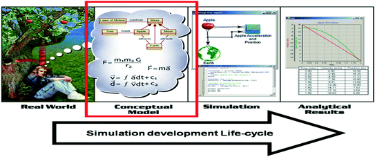
The role of the conceptual model in the Simulation development life-cycle [14]
Another important output of this step is a scenario. The scenario includes the types and numbers of major entities that must be represented within the simulation environment, a functional description of the capabilities, behavior, and relationships between these major entities over time, and a specification of relevant environmental conditions (such as urban terrain versus natural area, type of terrain, day/night, climate, etc.) that impact or are impacted by entities in the simulation environment. Initial conditions (e.g., geographical positions for physical objects), termination conditions, and specific geographic regions should also be provided.
A third important output of this step is the requirements for the simulation environment. This includes requirements for properties and behaviors that the simulation environment must represent, requirements for fidelity, as well as more technical requirements.
-
Step 3
Design simulation environment. Produce the design of the simulation environment that will be implemented in Step 4. This involves identifying member applications that will assume some defined role in the simulation environment (in HLA these are called federates) that are suitable for reuse, creating new member applications if required, allocating the required functionality to the member application representatives.
This step may include trade-off analysis to select the most appropriate member applications. Important outputs of this step include a list of member applications, allocated responsibilities, requirements gaps, and the simulation environment architecture.
-
Step 4
Develop simulation environment. Define the information that will be exchanged at runtime during the execution of the simulation environment, establish interface agreements, modify existing or develop new member applications (including models) if necessary, and prepare the simulation environment for integration and test.
Two important outputs of this step are a Simulation Data Exchange Model (SDEM) and simulation environment agreements. The Simulation Data Exchange Model describes the data that member applications can exchange at runtime (for HLA this corresponds to the FOM). Although the SDEM represents an agreement among member applications as to how runtime interaction will take place, there are other operating agreements that must be reached that are not documented in the SDEM. Such agreements are necessary to establish a fully consistent, interoperable, simulation environment. There are many different types of agreements, for instance, agreements on initialization procedures, synchronization points, save/restore policies, progression of time, object ownership, attribute update policies, security procedures, as well as algorithms that must be common across the simulation environment to achieve valid interactions among all member applications.
-
Step 5
Integrate and test simulation environment. Integration activities are performed, and testing is conducted to verify that interoperability requirements are being met.
-
Step 6
Execute simulation. The simulation is executed and the output data from the execution is pre-processed.
-
Step 7
Analyze data and evaluate results. The output data from the execution is analyzed and evaluated, and results are reported back to the user/sponsor.

The standard also includes a number of “overlays” for existing distributed simulation environment architectures such as DIS and HLA.
In the light of the LCIM described in Sect. 2, DSEEP steps 1–4 are of great importance. In these four steps the objectives, the conceptual model, the simulation environment design, and the simulation data exchange model and operating agreements, are developed. These are all important elements in the LCIM.
A more rigorous systems engineering approach to architecture development (and to achieving a higher level of interoperability) in these four steps is described in [15], “Simulation environment architecture development using the DoDAF”. This paper examines the application of US Department of Defense (DoD) Architecture Framework (DoDAF) and the related systems engineering concepts in simulation environment architecture development. In this approach the simulation environment is described using different, but interrelated, architectural viewpoints as shown in Fig. 18. Each architecture viewpoint defines several kinds of (UML) models (not to be confused with simulation models) to represent aspects of the system. The Operational Viewpoint, for example, is used in the Conceptual Analysis step of the DSEEP and defines model kinds for the description of operational activities and performers, workflow, information flow, and event traces for operational scenarios (in this case related to crtitical infrastructures). These models provide an implementation-independent representation of the systems and processes that the simulation environment must model and form one of the inputs to the simulation environment design.

DoDAF viewpoints per DSEEP step
While the DoDAF was not targeted for simulation environment development, the architectural constructs described by the DoDAF show great promise in terms of applicability to the simulation domain. By reusing these constructs, users may leverage a very broad and deep knowledge base of systems engineering experience to facilitate more capable and robust simulation environments in the future. The approach in this paper can be used to develop and document the conceptual model in a systematic way and achieve a higher level of interoperability between simulation models.
To summarize, the DSEEP is intended as a higher-level framework into which low-level management and systems engineering practices native to user organizations can and should be integrated. In general, this framework will have to be tailored to become a practical and beneficial tool for both existing and new simulation developments. The intent of the DSEEP is to specify a set of guidelines for the development and execution of these environments that stakeholders can leverage to achieve the needs of their application.
5 Federation Agreements Template
The Federation Engineering Agreements Template (FEAT) is intended to provide a standardized format for recording simulation environment agreements (see DSEEP step 4) to increase their usability and reuse. The template is an eXtensible Markup Language (XML) schema from which compliant XML-based simulation environment agreement documents can be created. XML was chosen for encoding agreements documents because it is both human and machine-readable and has wide tool support. Creating the template as an XML schema allows XML-enabled tools to both validate conformant documents, and edit and exchange agreements documents without introducing incompatibilities. Many of the artefacts generated in the DSEEP can be recorded using the FEAT.
The schema has been developed by the SISO and is published at [16]. The top level schema elements are shown in Fig. 19.

FEAT top level schema elements
The federation agreements are decomposed into the following eight categories:
-
1.
Metadata—Information about the federation agreements document itself.
-
2.
Design—Agreements about the basic purpose and design of the federation.
-
3.
Execution—Technical and process agreements affecting execution of the federation.
-
4.
Management—Systems/software engineering and project management agreements.
-
5.
Data—Agreements about structure, values, and semantics of data to be exchanged during federation execution.
-
6.
Infrastructure—Technical agreements about hardware, software, network protocols, and processes for implementing the infrastructure to support federation execution.
-
7.
Modeling—Agreements to be implemented in the member applications that semantically affect the current execution of the federation.
-
8.
Variances—Exceptions to the federation agreements deemed necessary during integration and testing.
Each category in the FEAT schema provides numerous elements that describe information that may be captured for a simulation environment. For example, Verification, Validation and Accreditation (VV&A) artefacts, Test artefacts, Security information, Member application data, objectives and requirements, hardware configurations, etc.
6 Summary
Modeling and Simulation (M&S) has become a critical technology in many domains. A set of coherent principles and standards are required to fully exploit the potential of M&S. Interoperability and composability are two challenges when federating simulation models. The seven Levels of Conceptual Interoperability (LCIM) between simulation models can be used to determine the level of interoperability between simulation models.
Federated simulations offer many advantages with respect to developing, using and maintaining complex simulation systems. The HLA offers a high quality standardised approach to federated simulation, supported by documentation, tools and an active user community. The advantages of open standards are:
-
Economy of Scale;
-
Comply with legislation;
-
Promote Interoperability;
-
Promote Common Understanding;
-
Introduce Innovations, Transfer Research Results;
-
Encourage Competition;
-
Facilitate Trade.
The challenges of common standards also need to be addressed:
-
Achieving consensus takes time. A user community must be established;
-
Not-Invented-Here syndrome needs to be overcome by involving all stakeholders;
-
Openness/Vendor Lock-In should be considered when selecting tools and suppliers;
-
Maintenance of standards must be considered to ensure progress and prevent loss of investment.
Simulation practitioners should use their limited resources to focus on their domain specific needs (simulation models, simulation data exchange models, simulation environment agreements, and verification methods) and benefit from existing tools and knowledge bases. I.e. focus on at least semantic interoperability between simulation models in a certain problem domain, and leverage existing standardised simulation middleware for the technical interoperability.
References
Petty M, Weisel E (2003) A composability lexicon (03S-SIW-023). In: SISO simulation interoperability workshop, Kissimmee, FL
Page E, Briggs R, Tufarolo J (2004) Toward a family of maturity models for the simulation interconnection problem (04S-SIW-145). In: SISO simulation interoperability workshop, Arlington, VA
Tolk A, Muguira J (2003) The levels of conceptual interoperability model (03S-SIW-007). In: SISO simulation interoperability workshop, Orlando, FL
Turnitsa CD (2005) Extending the levels of conceptual interoperability. In: Proceedings IEEE summer computer simulation conference, IEEE CS Press
Wang W, Tolk A, Wang W (2009) The levels of conceptual interoperability model: applying systems engineering principles to M&S. In: Spring simulation multiconference, San Diego, CA, USA
SISO (2015) Standard for guidance, rationale, and interoperability modalities (GRIM) for the real-time platform reference federation object model (RPR FOM), Version 2.0 (SISO-STD-001-2015), SISO
SISO (2006) Standard for base object model (BOM) template specification (SISO-STD-003-2006), SISO
IEEE (2010) IEEE standard for modeling and simulation (M&S) high level architecture (HLA)—framework and rules (IEEE 1516-2010), IEEE
IEEE (2010) IEEE standard for modeling and simulation (M&S) high level architecture (HLA)—federate interface specification (IEEE 1516.1-2010), IEEE
IEEE (2010) IEEE standard for modeling and simulation (M&S) high level architecture (HLA)—object model template (IEEE 1516.2-2010), IEEE
Möller B (2007) An overview of the HLA evolved modular FOMs (07S-SIW-108). In: SISO simulation interoperability workshop, Norfolk, VA
Run-time infrastructure (simulation) (2016) Wikipedia, 2016. Available: http://en.wikipedia.org/wiki/Run-time_infrastructure_(simulation). Accessed 2016
IEEE (2010) IEEE recommended practice for distributed simulation engineering and execution process (DSEEP) (IEEE 1730-2010), IEEE
Conceptual modeling (CM) for military modeling and simulation (M&S) (RTO-TR-MSG-058), NATO Science and Technology Organization, 2012
Berg T, Lutz R (2015) Simulation environment architecture development using the DoDAF (15F-SIW-019). In: SISO simulation interoperability workshop, Orlando, FL
SISO (2013) SISO federation engineering agreements template (FEAT) programmer’s reference guide. Available: http://www.sisostds.org/FEATProgrammersReference
Acknowledgement and Disclaimer
This chapter was derived from the FP7 project CIPRNet, which has received funding from the European Union’s Seventh Framework Programme for research, technological development and demonstration under grant agreement no. 312450.
The contents of this chapter do not necessarily reflect the official opinion of the European Union. Responsibility for the information and views expressed herein lies entirely with the author(s).
Author information
Authors and Affiliations
Corresponding author
Editor information
Editors and Affiliations
Rights and permissions
Open Access This chapter is licensed under the terms of the Creative Commons Attribution 4.0 International License (http://creativecommons.org/licenses/by/4.0/), which permits use, sharing, adaptation, distribution and reproduction in any medium or format, as long as you give appropriate credit to the original author(s) and the source, provide a link to the Creative Commons license and indicate if changes were made.
The images or other third party material in this chapter are included in the chapter’s Creative Commons license, unless indicated otherwise in a credit line to the material. If material is not included in the chapter’s Creative Commons license and your intended use is not permitted by statutory regulation or exceeds the permitted use, you will need to obtain permission directly from the copyright holder.
Copyright information
© 2016 The Author(s)
About this chapter
Cite this chapter
Huiskamp, W., van den Berg, T. (2016). Federated Simulations. In: Setola, R., Rosato, V., Kyriakides, E., Rome, E. (eds) Managing the Complexity of Critical Infrastructures. Studies in Systems, Decision and Control, vol 90. Springer, Cham. https://doi.org/10.1007/978-3-319-51043-9_6
Download citation
DOI: https://doi.org/10.1007/978-3-319-51043-9_6
Published:
Publisher Name: Springer, Cham
Print ISBN: 978-3-319-51042-2
Online ISBN: 978-3-319-51043-9
eBook Packages: EngineeringEngineering (R0)