
Abstract
The most common structural system of the precast industrial buildings in Europe consists of an assemblage of cantilever columns tied together with beams. Typical beam-to-column connection in these structures is constructed with steel dowels. Although this system has been used for decades, its seismic response was poorly understood, which reflected in ambiguous code requirements and conservative approach. Therefore, along with innovative precast structural solutions (not discussed in this paper), this system was the main focus of the continuous European research in the past two decades. The key results of this vast research effort (including unprecedented cyclic, PSD and shake table experiments on large-scale structures) led by the associations of the precast producers in Europe and the Politecnico di Milano are presented and discussed in this paper. The details are provided for the work done at the University of Ljubljana. The results of these research projects led to some major modifications and improvements of the relevant chapter in Eurocode 8, when this was evolving from the initial informative annex to the final code provision. Refined FEM models for the complex behaviour of the dowel beam-to-column connections as well as macro models for the post-critical analysis of the complete structures were proposed. Single-storey and multi-storey structures were investigated and the design formulas to estimate high shear and storey-force amplification due to higher-modes effect in multi-storey structures were derived. The design guidelines for connections of precast structures under seismic actions were prepared. Systematic risk studies were done indicating that this structural system can be safe in seismic regions if all Eurocode 8 provisions as well as the recommendations based on the presented research are considered. These include the capacity design of the connections. Behaviour factor for such precast systems was studied and the values initially proposed in preEC8 were modified (increased). However, it was shown that drift limitations typically govern the design and that the nominal value of the behaviour factor is not so decisive. The key factors contributing to the good seismic behaviour of this system (assuming that the connections are properly designed) is the low value of the compressive axial force in the columns confined with adequate hoops and the overstrength caused by drift limitation requirements. Cladding-to-structure interaction has been one of the most poorly understood components of the system, which is now the topic of the on-going research.
You have full access to this open access chapter, Download chapter PDF
Keywords
- Behaviour Factor
- Energy Dissipation Capacity
- Incremental Dynamic Analysis
- High Mode Effect
- Incremental Dynamic Analysis Curve
These keywords were added by machine and not by the authors. This process is experimental and the keywords may be updated as the learning algorithm improves.
4.1 Introduction
Seismic behaviour and seismic safety of precast structures has been frequently discussed. However, when such discussion refers to precast structures in general, it is pretty much displaced and meaningless. Precast buildings are defined as structures made of pre-fabricated elements assembled into the structural system on the construction site. Obviously the behaviour of such systems depends predominantly on the details of the connections, which may differ essentially from one to the other precast system. So, empirical evidence from the past earthquakes shows everything from good structural response (Fig. 4.1) to complete disasters (Fig. 4.2).

Undamaged structural system of the precast industrial building after the L’Aquila 2009 earthquake

Large panel precast structure standing among the rouble of the precast frames, which caused a terrible tragedy during the Spitak 1988 earthquake
While the tragedy of the Spitak 1988 earthquake in Armenia (EERI 1989) imposed large distrust onto precast structures in general, it should be noticed that at the same time large panel precast structures behaved quite well in spite of the poor construction practice. Therefore any generalized and superficial conclusions that precast structures are bad or good are non-professional and unacceptable. We should be fully and constantly aware that even a single life, which might be lost in the structures designed by ourselves or by the codes developed by us imposes a huge moral obligation onto us.
For these reasons the specific precast system, discussed in this paper, was extensively studied for two decades. Based on these results the relevant sections of Eurocode 8 were substantially modified and hopefully improved. The overview of the main research results is given in the following sections. Although, in general the observations are positive, one should be aware of the strict design requirements that are needed to ensure good performance. It is hoped that this presentation will give better insight into the seismic response and behaviour of this frequently used precast system, which is required for the objective evaluation of its performance.
Simply speaking, the analysed system consists of an assemblage of cantilever columns tied together with beams (Figs. 4.3 and 4.4).

Schematic representation of the structural system of an industrial building

Structural system consists of an assemblage of cantilever columns tied together with beams and floor structures
The key element in this system is the beam-to-column connection. Among many different solutions the dowel beam-to-column connection is most frequently used (Fig. 4.5). This connection is practically hinged and the system indeed behaves as an assemblage of cantilever columns tied by beams.

Beam-to-column dowel connection is clearly seen in the upper floor. In the lower floor the beam has been already installed and the steel sockets will be grouted
This precast system has been used in Europe to construct about 50 millions of square meters of buildings per year. Such buildings house a predominant share of industrial facilities in many European countries. Recently they are also used for multi-storey office buildings and shopping centres housing thousands of people (Fig. 4.6). Therefore the potential seismic risk is high. However, due to the complex and complicated seismic behaviour of these buildings our knowledge is still limited and the design practice and codes need further improvements.

The analysed precast system is frequently used for large multi-storey buildings. The picture shows a huge shopping centre in Ljubljana to be visited by several 10,000 visitors a day
The paper is built predominantly on the research results gained within several large EU projects organized during the past two decades. The authors have been actively participating in these projects and cooperating with large consortia (Fischinger et al. 2011b) of European Associations of precast producers, enterprises and research institutions. While the results were always discussed within the consortia and the conclusions were typically agreed by all participants, the opinions and conclusions presented in this paper are those of the authors and do not always reflect the views of all the partners.
Most important general results of these projects are only briefly summarized and they are used as the framework of the paper. The details are then provided for the work done at the University of Ljubljana with the particular emphasis on the response of beam-to-column dowel connections and cladding-to-structure connections, inelastic response analysis of precast industrial buildings, behaviour factors and higher modes effects in multi-storey buildings. The most important result of this research has been the improvement of the design practice governed by the modified provisions in the relevant chapter of Eurocode 8 (CEN 2004), which has been immediately applied by sponsoring associations and companies.
4.2 Post-Earthquake Inspections
In spite of the frequent use of the analysed precast system, the information about its behaviour during the earthquakes has been sparse and sometimes controversial (see also the Introduction). Although good structural behaviour prevails (Fig. 4.7), it sometimes goes hand in hand with collapses. Again one should pay attention on seemingly small but important details. During Friuli earthquake, good behaviour was observed (Fajfar et al. 1978; EERI 1979). However, in Friuli quite long period structures were exposed to short, high-frequency ground motion with relatively weak energy content and low displacements in the range of predominant structural periods. During the recent Emilia earthquakes, which occurred near-by, a lot of damage was reported (i.e. Bournas et al. 2013a). But here, most of this damage should be attributed to the fact that the majority of the buildings were not designed for the earthquake action (this region has been considered as seismic only from the year 2003 on). However, there were also some collapses in new buildings. A strong low frequency content of the N-S component of the May 29th earthquake might contribute to the increased damage. Similar reason might increase damage in the case of Vrancea earthquake (Tzenov et al. 1978) and during some Turkish earthquakes.

Structural system of most precast industrial buildings designed for seismic action remained undamaged during recent Italian earthquakes
After the other recent Italian earthquake – L’Aquila, good structural behaviour of the precast industrial buildings was reported (Figs. 4.1 and 4.7; Toniolo and Colombo 2012). But in both, Emilia and L’Aquila earthquakes heavy damage to claddings was observed (Fig. 4.8; Toniolo and Colombo 2012). The problem of claddings will be discussed in a separate chapter.

Many cladding panels fell off the structures during recent Italian earthquakes (Toniolo and Colombo 2012)
During the Montenegro earthquake (Fajfar et al. 1981) damage to precast structures was small and it was predominantly due to the soil effects and the rotation of foundations (Fig. 4.9). After the recent earthquakes in Turkey (Saatcioglu et al. 2001; EERI 2000; Arslan et al. 2006) statistics show small, but nevertheless considerable number (3 % of the total inventory) of collapses and heavy damage (Fig. 4.10).

Collapse of the roof structure in Montenegro earthquake due to soil effects and poor connections

This collapsed precast structure illustrates the importance of ties in precast buildings
Regardless all the differences in observations, the main causes of the damage to the investigated precast system were similar in all cases and all countries:
-
Failure of the connections, as the main cause of damage and collapse (Figs. 4.2, 4.9, 4.11 and 4.12);
Fig. 4.11 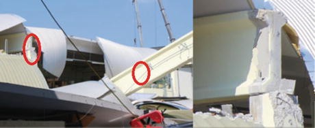
Collapse of the beam during Emilia earthquake due to the loss of the seating; general view – left and the detail of the support – right (Bournas et al. 2013a)
Fig. 4.12 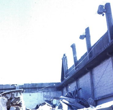
Collapse of the roof system during Montenegro earthquake due to soil effects and poor connections
Fig. 4.13 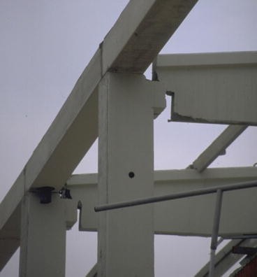
Displacements are typically very large
-
Lack of mechanical connections between the columns and roof girders in old buildings and in supposedly aseismic regions (Bournas et al. 2013a);
-
Lack of ties (Fig. 4.10);
-
Insufficient in-plain stiffness of the roof/floor structures;
-
Torsional response due to asymmetric stiffness distribution;
-
Poor detailing of hoop reinforcement in columns (Figs. 4.14 and 4.15);
Fig. 4.14 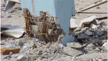
Collapse of a precast column due to poor confinement
Fig. 4.15 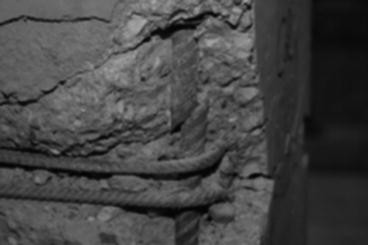
The mistake in the construction of the hoops (and the resulting impaired confinement) led to heavy damage of the precast column in the PRECAST full-scale test
-
Unpredicted large displacements (Fig. 4.13) associated with too-short seating and poor connections;
-
Poor foundation in soft soil (Fig. 4.12);
-
Detachment of claddings (Fig. 4.8).


4.3 Past Research – General Overview
Compared to cast-in-place structures, all types of precast structures have received relatively little attention which has reflected in slow development of codes. In particular, precast industrial buildings, which are discussed in this paper, are not used in some countries (USA, Japan, New Zealand) that lead in earthquake engineering. Research there has predominantly addressed systems with flexural-resistant and prestressed connections (i.e. PRESS – PREcast Seismic Structural System; Priestley 1996; Shiohara and Watanabe 2000). Consequently, there has been very little information about the precast industrial buildings in the state-of the-art (at the time of publication) reports as it was the ATC-8 action – Design of prefabricated buildings for earthquake loads (ATC-08 1981). More recent report (FIB 2003) of the fib-Task group 7.3 (the first author of this paper was a member of the group) contains some, but still very limited information. Surprisingly so, in the past even the major Balkan research project (UNDP/UNIDO 1985) addressed predominantly the large panel precast systems with very little attention to precast industrial buildings.
Due to the poor knowledge the only possible and right solution in the early developments of Eurocode 8 was to adopt quite conservative approach for seismic design of precast (industrial) buildings. Simply speaking, practically elastic response was required for the analysed system (see also the discussion of the behaviour factors in Sect. 4.10). This was a great shock for the industry, used to the same or at least similar seismic forces and structural details in precast and cast-in-situ structures. The authors of this paper fully support the idea that energy dissipation capacity of any precast system to be used in mass production should be first experimentally and analytically verified. For the precast system addressed in this document, systematic verification has been done within five large research projects (Toniolo 2012):
-
Cyclic and PSD tests of precast columns in socket foundations (ASSOBETON; 1994/96)
-
Comparison of the seismic response of the precast and cast-in-situ portal frame (ECOLEADER project; 2002/03)
-
PRECAST – Precast Structures EC8; 2003/06
-
SAFECAST – Performance of Innovative mechanical Connections in Precast Building Structures under Seismic Conditions; 2009/12
-
SAFECLADDING – Improved Fastening systems of Cladding Wall Panels of Precast Buildings in Seismic Zones; on-going project; 2013/15
All these projects were sponsored by the associations of precast producers and SMEs in Italy, Greece, Turkey, Portugal, and Spain, which demonstrates the interest of the industry in this topic. The research providers (European Laboratory for Structural Assessment, JRC-ELSA; Istanbul Technical University – ITU; LABOR; National Laboratory of Civil Engineering in Lisbon, LNRC; National Technical University of Athens, NTUA; Politecnico di Milano., POLIMI and University of Ljubljana; UL) were coordinated by The Politecnico di Milano under the scientific leadership of Professor Giandomenico Toniolo. The key activities and results of these projects are very briefly introduced in the next section, followed by more detailed description of the selected results contributed by the research group in Ljubljana.
4.4 European Research in Support of the Eurocode-8 Developments
4.4.1 Cyclic and PSD Tests of Precast Columns in Socket Foundations (ASSOBETON)
The aim of the research (Saisi and Toniolo 1998) was to investigate the ductility and energy dissipation capacity of precast columns at realistic foundation conditions (Fig. 4.16). Substantial ductility (3.5–4.5) was demonstrated. This is to be expected for an element with relatively low compressive axial force (typical for the columns in one-storey industrial buildings), symmetric reinforcement and considerable confinement. Good behaviour was further enhanced due to the absence of the splice in the critical region and construction in controlled environment. It should be noted that the larger ductility displacement value was achieved only if the spacing of the hoops in the critical region was 3.5 times of the longitudinal bar diameter (about 7.5–10 cm). It is interesting to note that this complies with the practice in Slovenia (former Yugoslavia) after the Montenegro earthquake. On the other hand the valid Eurocode requirements can be less stringent.

ASSOBETON tests on precast columns with pocket foundation performed at ELSA
4.4.2 Comparison of the Seismic Response of the Precast and Cast-In-Situ Portal Frame (ECOLEADER)
The project (Ferrara et al. 2004; Biondini and Toniolo 2002; Biondini and Toniolo 2004), approved for ECOLEADER (European Consortium of Laboratories for earthquake and Dynamic Experimental research) funding, was aimed at demonstrating the practical equivalence between the behaviour factor of precast and cast-in-situ single-storey industrial buildings (Fig. 4.17).

Precast (left) and cast-in-situ (right) ECOLEADER prototypes during testing
Both structures were designed to have the same fundamental period. Quite similar behaviour of both structures was observed – Fig. 4.18

The PSD response of the precast (left) and cast-in-situ (right) ECOLEADER prototypes
This supports the supposition that the same behaviour factor can be used for the precast and cast-in-situ structure of this type (Biondini and Toniolo 2002, 2004). But this result by itself does not mean, in any case, that either of the structures had the same energy dissipation capacity as the multi-storey, multi-bay frame designed with the weak-beam-strong-column concept (see discussion in Sect. 4.10). Therefore further research of this important issue was needed.
4.4.3 PRECAST – Seismic Behaviour of Precast Concrete Structure with Respect to EC8
The goal of the PRECAST project (Toniolo 2007) was to assess (experimentally and numerically) and to calibrate the design rules for (industrial) precast concrete structures in Eurocode 8. It was a logical continuation of the ECOLEADER project. Similar to ECOLEADER a full scale one-storey precast structure (Figs. 4.19a, b) was tested with PSD and cyclic experiments. However, this structure, supported by six 5 m high columns, had two bays and realistic floor/roof structure (the one in ECOLEADER was rigid slab) composed with slab panels, once oriented in the direction of the loading (Fig. 4.19b), and the other time perpendicular to this direction (Fig. 4.19a). In initial – elastic tests, cladding panels were added (Fig. 4.19a), which were then removed at higher levels of loading. Tolmezzo record modified to fit EC8 (soil B) spectrum with peak ground acceleration 0.05, 0.14, 0.35 g (design acceleration) and 0.525 g was used in tests. PRECAST project provided valuable information about the seismic response, which was subsequently used in numerical analyses (see Sect. 4.5) and systematic risk studies (see Sect. 4.9).

(a) PRECAST EC8 building with cladding panel; load perpendicular to the slab panels. (b) PRECAST EC8 building; claddings removed; load in the direction of panels
Most important results of the project were:
-
The structure had large overstrength. Yielding in the columns was not observed until the last PSD test with maximum ground acceleration 0.525 g. Only much stronger cyclic loading, applied at the end of testing, imposed near collapse mechanism. It should be noted, however, that even this very large structure had still smaller spans (mass) compared to those in real structures.
-
Therefore a systematic numerical study was done showing good response and acceptable risk for a whole set of realistic one-storey structures used in practice (Kramar et al. 2010a).
-
Extremely large top displacements (8 % drift or 40 cm) were recorded at the ultimate stage. As a surprise yield drift was over 2 %. See more details in the following Sect. 4.5, discussing the inelastic model for the columns.
-
Seemingly quite flexible floor structure worked pretty much as a rigid diaphragm, regardless of the orientation of the floor panels
-
Cladding panels changed the response significantly
4.4.4 SAFECAST – Performance of Innovative Mechanical Connections in Precast Building Structures Under Seismic Conditions
As discussed in the previous section, PRECAST project demonstrated good seismic performance of one storey precast industrial buildings. However, this result was still far for being conclusive. First of all, it has been obvious that realistic behaviour of connections determines the response of any precast structure. And even the capacity of most commonly used connections was not known. Furthermore, the inelastic response and the behaviour of multi-storey structures were far from being understood. To fill these gaps in the knowledge project SAFECAST was initiated (Toniolo 2012). Together with many parallel tests on individual existing and innovative connections, the main experimental research consisted of PSD tests on a full-scale 3-storey precast concrete building, performed at ELSA (Fig. 4.20; for the details of the structure see Negro et al. 2013 and Bournas et al. 2013b).

The SAFECAST structure tested at ELSA
To use the expensive specimen as efficiently as possible, for different structural solutions were tested one after another (Fig. 4.21). The level of damage in the columns was limited to enable to carry out this sequence of tests.

Structural layouts of the four prototypes (Bournas et al. 2013b)
Structural system of the prototype 2 complied with the definition given in the introduction of this paper (an assemblage of multi-storey columns with all hinged beam-to-column joints). In prototype 1 two symmetrically placed precast structural walls were added to stiffen the system. These walls were disconnected after the test of the prototype 1. In prototype 3 it was attempted to reduce the flexibility of the system by making the joints in the top story moment-resistant. Innovative dry connections were installed and activated for this purpose. In prototype 4 all joints were subsequently made moment-resistant. Different floor diaphragms were used in each floor. Box type elements were used in the first floor. Pre-topped double tee diaphragm was used in the second floor. Separated slab elements were installed in the third floor to simulate openings in the roofs used for architectural reasons. The same ground motion as in the case of PRECAST was used. Prototypes 1 and 2 were exposed to maximum ground accelerations 0.15 and 0.30 g, prototype 3 to agmax = 0.3 g and prototype 4 to agmax = 0.3 g and 0.45 g.
Only brief overview of the key observations and conclusions is given below:
-
Overall, the response of the structure was good up to the ultimate limit state design levels.
-
However, extremely high influence of higher mode effects was observed in prototype 2 (see Sect. 4.8 for more detailed analysis). This imposes very high seismic storey forces and the demand on joints. This demand would not be identified by traditional design. The structure was very flexible with inter-story drifts up to 2.4 %. It is believed that such multi-storey precast structures are difficult to be designed without some kind of stiffening measures.
-
The use of precast structural walls in prototype 1 reduced the maximum inter-story drift to 0.7 %. At the same time the rigid diaphragm action was not impaired (with a certain exception of the top story with separated floor panels). But it should be noted that the walls (with the same stiffness) were placed symmetrically in the floor plan. Asymmetry in real design may impose significant torsional effects and large forces to transfer through the floor structures into the walls.
-
Making moment-resistant connections only at the top floor in the prototype 3 (which could be a practical solution in real life) reduced the fundamental period for only 23 % in comparison with the structure with hinge joints.
-
The solution in prototype 4 was more efficient. However, the innovative dry joints were only semi-rigid (large slips were observed due to the problems in technology of construction)
-
The tests provide valuable data for numerical modelling
SAFECAST project provided important knowledge about the strength and deformation capacity of the most common types of connections used in the design practice (in particular beam-to-column connection, which will be discussed in more detail in Sect. 4.6). Additionally many innovative connections were proposed and tested (these results cannot be published here).
The most important outcome of the SAFECAST project, based on the mutual effort of all the partners in the consortium, is a set of design guidelines for connections of precast structures under seismic actions (Negro and Toniolo 2012). It is hoped that this document (or at least parts of it) will be subsequently incorporated into Eurocode 8 provisions.
These guidelines are based on the experience obtained by testing a large number of different typical connections. However, it is obvious that there are many different variations and even completely different types of connections used in the construction practice. Therefore, one should be extremely careful when extrapolating the design guidelines to other types of connections (more detailed discussion is given in Sect. 4.10) (Fig. 4.22).

Most important result of the SAFECAST project
4.4.5 SAFECLADDING – Improved Fastening Systems of Cladding Wall Panels of Precast Buildings in Seismic Zones
SAFECAST project indicated that the most poorly (in fact wrongly) understood connection in the precast industrial buildings is the cladding-to-structure connection. It was traditionally supposed that the existing connections separate the cladding panel from the structure. Panels were usually considered only as added mass in the structural model. Therefore these connections were designed for the inertia forces contributed by the mass of the panel only as well as only in the direction perpendicular to the panel. However, in many cases traditional connections cannot accommodate the very large relative displacements between the structure and the panels. In such a case the panel and the columns begin to act together as a single structure. The connections are then loaded by inertia forces contributed by the total mass of the structure, which act in the plane of the panel. This observation was drastically confirmed during the recent L’Aquila and Emilia earthquakes (Figs. 4.8 and 4.23).

Failure of the traditional hammer-head connection during the Emilia earthquake
In SAFECLADDING project four different solutions to this problem are being proposed and analysed:
-
Additional research is under way to understand better the capacity and the demand in the case of the existing connections. This will improve the design practice. However, it is expected that in cases of strong earthquakes the collapse of existing types of connections cannot be always prevented. In such cases second line of defence measures will be proposed. This research will be presented in more detail in Sect. 4.7.
-
New connections allowing for larger relative displacements will be proposed.
-
Integrated (dual) systems are studied. In these studies panels are designed as a part of the lateral resisting (dual) system
-
Dissipative connections seemed to be very promising solution.
In addition to a large number of tests on the individual types of connections the key experiment will be again performed at ELSA. A sequence of 22 tests are planned to be performed on a single-storey two-bay full-scale structure. In each test the arrangement of panels and the type of the connections will be varied.
4.5 Modelling of the Inelastic Seismic Response of Slender Cantilever Columns
A slender cantilever column may represent a class of one-storey industrial buildings with strong connections. Therefore, we start more detailed discussions of the research done with the presentation of the inelastic model for slender columns. Whatever, this problem might appear trivial and several extensive data bases (PEER 2007; Panagiotakos and Fardis 2001) related to the cyclic behaviour of RC columns exist, practically no information was available about the behaviour of very slender cantilever columns having shear span ratios of more than ten. This is especially true for the post-peak behaviour at large drift ratios, which should be understood and clearly defined when using up-to-date performance-based procedures and seismic risk studies. Therefore, a numerical model based on the full-scale PSD and cyclic tests done at ELSA (see Sect. 4.4.3) within the PRECAST project (Toniolo 2007) was proposed and verified by the research team at UL (Kramar 2008; Fischinger et al. 2008).
The plan of the tested structure (Fig. 4.19; walls were disconnected) is given in Fig. 4.24. The shear-to-span ratio of the columns was 12.5. They were designed according to the EC8 standard. The study was later extended to the lightly reinforced columns, not observing the minimum requirements of EC8.

Plan of the analyzed PRECAST structure, showing the typical column cross-section
Very specific behaviour of the columns with high shear-span ratio was observed (Fischinger et al. 2008). The deformability and the deformation capacity of the columns were large (Fig. 4.25). The yield drift was 2.8 % (much more than the values reported for columns with smaller shear-spans). In the final cyclic test, the columns exhibited quite stable response up to a large drift close to 7 %. Buckling of the longitudinal reinforcement bars then led to subsequent tension failure of the bars in the first column. The strength of the structure dropped considerably, but it was stabilized by the other five columns. A 20 % drop in maximum strength was observed at about 8 % drift, following considerable in-cycle strength degradation and the flexural failure of several columns. Very short height of the plastic hinge (only half of the cross-section dimension of the column) was observed.

The ultimate drift of 8 % (top displacement equal to 40 cm) was observed in PRECAST full-scale test
The beam-column model with lumped plasticity was chosen. However, most existing hysteretic models had problems to describe the observed behaviour. The best results were obtained using Ibarra hysteretic model (Ibarra et al. 2005) that accounts for history-dependent strength and stiffness deterioration. The behaviour is first described by a monotonic backbone curve. Pre-capping and post-capping cyclic strength deterioration, based on the energy dissipation criterion, is then considered (Fig. 4.26). Haselton (2006) has calibrated Ibarra hysteretic model for a large number of column tests. If Haselton expressions, except for the yield drift (which was determined analytically taking into account empirical corrections for pull-out and shear-slip), were used, the match of the analytical and experimental results was very good (Figs. 4.4 and 4.27).

Strength deterioration in the Ibarra’s model

Numerical versus experimental results
4.6 Cyclic Response of Beam-to-Column Dowel Connections
Beam-to-column connections are extremely important for the integrity and safety of the precast industrial structure. The majority of collapses during earthquakes are due to the fall of the beam. Nowadays it is obvious that the connection should not rely only on the friction and that some kind of mechanical connection should be provided. The most common solution is the use of steel dowels (Fig. 4.28). This option has been used for decades. Nevertheless, the design (if done at all) was predominantly based on engineering feeling and the requirements of non-seismic loading. However, the correct approach would be the use of the capacity design, which is in fact required by Eurocode 8. For this we obviously need to know capacity of the dowel connection and the demand imposed during seismic action (the latter will be discussed in Sect. 4.8). Neither of them was understood enough. Therefore a good deal of the experimental and numerical research effort within SAFECAST was devoted to this connection. Static and cyclic tests at large relative rotations between the beam and column were done at UL in Ljubljana (Kramar et al. 2010b; Fischinger et al. 2012a, 2013) (Figs. 4.29 and 4.28), static, cyclic and shake table test were performed at NTUA in Athens (Fig. 4.30) and shake table tests were done AT LNEC in Lisbon (Fig. 4.31).

Typical eccentric beam-to-column dowel connection, which was tested at UL

Test of the dowel connection at large relative rotation between the beam and column

Shake table test of the beam-to-column dowel connection at NTUA

Shake table test of the beam-to-column dowel connection at LNEC
In this paper we present mainly the research performed in Ljubljana. Three types of connections were tested (Fig. 4.32): (1) single centric dowel (typical for roof beam to column connection), (2) single eccentric dowel (for comparison) and (3) two eccentric dowels (typical for floor beam to column connection).

Typical beam-to-column connections tested at UL
While several experiments were done in the past to estimate the dowel strength (i.e. Vintzeleou and Tassios 1987) they were restricted to pure shear and specimen without hoop reinforcement. Special purpose of the tests at UL was to study the behaviour of the connections at very large relative rotation between the beam and the column (Fig. 4.25) observed in the previous PRECAST project. It should be noted that this large drifts are needed to justify the energy dissipation capacity (behaviour factor) assumed in the design.
Two types of failure of the investigated connections were identified: (a) the rupture of the dowel and crushing of the surrounding concrete (Fig. 4.33) and (b) the failure of the beam to column joint due to the insufficient tension strength of concrete and stirrups surrounding the dowel (Fig. 4.34).

Rupture of the dowel in the case of large concrete cover

Failure in the case of small concrete cover and in the case of the insufficient tension strength of concrete and stirrups surrounding the dowel
The type of the failure and strength of the connections strongly depended on: (a) the distance of the dowel from the edge of the column and beam, (b) the amount of the provided stirrups in beam and column, and (c) the amount of relative rotations between the column and the beam. Due to the large relative rotations, the 20 % reduction of the strength of the connections was identified. In asymmetric connections the strength was also influenced by the direction of the loading, since the distance of the dowel from the edges of column and beam was different. It has been confirmed that the cyclic strength of the connections was 50–60 % of the strength measured during the monotonic tests (as it was noticed in the previous research). In the majority of cases, the formulas existing at the time of the experiment, which can be used to estimate the strength of the dowel itself, underestimated the actual strength. The difference between the predicted and actual strength was even larger in the case of other types of failure.
To understand the mechanism of the response better and to propose the design formulas and procedures, extensive numerical studies were done. FEM models were developed and used (Zoubek et al. 2013b) The models and the results are presented in the following subsections for (a) dowels embedded deep into the column’s concrete core – large concrete cover (c ≥ 6dd; c is the dimension of the concrete cover and dd is the diameter of the dowel) and (b) dowels placed close to the edge of the column – small concrete cover (c ≤ 6dd).
4.6.1 Capacity of the Beam-Column Connection with Dowels Embedded Deep in the Concrete Core
Behaviour of dowels embedded deep in the concrete core is mainly characterized by the dowel action mechanism for which numerical models have already been developed and experimentally tested in some previous studies (Dulascska 1972; Højlund-Rasmussen 1963; Engström 1990; Vintzeleou and Tassios 1986; Zoubek et al. 2013a, b). The simple models assume that the strength of the dowel is reached at simultaneous yielding of the dowel and crushing of the surrounding concrete (see Fig. 4.35).

Failure mode of the dowel mechanism
Assuming the failure mechanism presented in Fig. 4.35, the following formula can be used to analytically evaluate the ultimate resistance of the dowel connection at monotonic loading:
Coefficient α0 varies among different authors from 1.0 to 1.3 and mainly depends on the increase of the concrete compressive strength due to tri-axial state of stresses in front of the dowel (f * cc in Fig. 4.35).
In the case of cyclic loading the strength should be reduced because of the cyclic degradation of concrete and steel. Vintzeleou and Tassios (1986) suggested a reduction factor of 0.7 (0.5 for design purposes):
Based on the results of the experiments performed in the frame of the SAFECAST project (Psycharis and Mouzakis 2012) proposed a modified formula, which accounts for cyclic behaviour of the realistic beam-to-column dowel connections:
where C0 is a factor ranging between 0.9 and 1.1 and takes into account the influence of relative rotations between the beam and the column . Based on the tests performed at the University of Ljubljana (see Sect. 4.6) value of 0.9 should be used to account for the strength reduction due to the large relative rotations. γ R is a general safety factor to account for the uncertainties in the experimental procedure and the limited number of experimental data used in the derivation of this formula. Value of 1.3 for γ R was suggested in Psycharis and Mouzakis (2012). This formula was adopted in the Design recommendations (Negro and Toniolo 2012), but γR was not included.
This expression is predominantly empirical and no detailed analysis of the failure mechanism leading to this result was done within the SAFECAST project. Therefore the understanding of the behaviour was incomplete and consequently the generalization of the formula to the cases not tested within the project was difficult. To get a generally applicable tool to estimate the capacity of the dowel connections some sophisticated finite element analyses were performed to understand the behaviour in detail and to support the formula (Zoubek et al. 2013a, b). Good correlation between the numerical results and the values given by the formula has demonstrated the ability of the proposed numerical tool.
4.6.2 Capacity of the Beam-Column Connections with Dowels Placed Close to the Edge of the Column
In the case of dowel connections with dowels placed close to the edge, premature splitting of concrete can occur before the dowel mechanism, described above, can develop (Fig. 4.36).

This brittle failure was thoroughly investigated in Fuchs et al. (1995; Fig. 4.36a). Based on the extended experimental study, the following formula was proposed to predict the capacity of the eccentric anchor:
where l < 8 d d is the effective embedment depth and c 1 is the distance from the centre of the dowel to the free edge of the concrete element in the direction of loading. To take into account the dimensions of the concrete element and the eccentricity of loading in the case of a group of anchors (coefficients ψ 4 and ψ 5), the following correction of the resistance R no is needed:
where A v is the actual projected area at side of concrete member, idealizing the shape of the fracture area of individual anchor as a half-pyramid with side lengths 1.5 c 1 and 3c 1 (Fig. 4.1), while A vo is the projected area of one fastener unlimited by corner influences, spacing or member thickness, idealizing the shape of the fracture area as a half-pyramid with side length 1.5 c 1 and 3c 1. Similar formulas are also included in CEN/TS 1992-4-2 and Design Guidelines for Connections of Precast Structures under Seismic Actions (Negro and Toniolo 2012).
The presented closed expressions usually underestimate the capacity of the actual eccentric beam-to-column dowel connections due to the inadequate evaluation of the contribution of the confining reinforcement, which definitely helps to improve the integrity of the connection and prevent the brittle failure. In CEN/TS 1992-4-2 the resistance of the eccentric anchor is allowed to be increased by factor 1.4 if closely spaced stirrups are provided in the region around the connection. Even though the standard recognizes the importance of the confinement, the approach seems to be too simplified. The authors therefore suggest an alternative method. The capacity of the eccentric dowel connection should be estimated by appropriate usage of the Strut and tie model (Fig. 4.3). The compressive stresses in concrete are equilibrated with the tension stresses in the confining reinforcement. The assumed directions of the compression diagonals for the connection with one or two dowels were supported with the finite element model presented in Zoubek et al. (2013a, b, last column in Fig. 4.37).

Proposal for the calculation of the resistance of the eccentric dowel connection with one or two dowels using truss and tie model
The procedure was tested against the experimental results obtained within the SAFECAST procedure (Zoubek et al. 2014a, b). Very good match with the experimental results was demonstrated. It was also shown that the formulas proposed in CEN/TS (2005) greatly underestimate the capacity of the connections in the case of spalling of concrete edge.
4.7 Cyclic Response of Typical Cladding-to-Structure Connections
Cladding-to-structure connections have been among the less understood connections in industrial buildings. Actually the problem was typically avoided by assuming that claddings are separated from the structure. During stronger earthquakes the relative displacements are so large that this is definitely not true and very complex interaction is imposed. To analyse this interaction one must know the imposed demand as well as the capacity of the connection. Up to now the extensive study of the capacity of the most typical connections used in Europe was already completed within the SAFECLADDING project.
Typical mechanical connections, which are used to attach the cladding panels to the structural system of precast buildings depend on the orientation of the panels. Vertical as well as horizontal panels are widely used. Therefore, some typical representatives of both groups of connections were included in the plan of the experiments. Three types of mechanical connections, presented in Fig. 4.38 were tested.

Tested cladding-to-structure connections (a) Typical connection of the vertical panel and the beam. (b) Typical angle connection. (c) The connection, which is used to attach the horizontal panels to the columns
In order to optimize the experiments as much as possible, the same setup (see Fig. 4.39) was used for all investigated connections (Fig. 4.39).

Basic configuration of the setup
Altogether 30 tests were performed. In general three types of tests were accomplished:
-
Uniaxial shear tests (see Fig. 4.40a): The load was applied in the horizontal direction in parallel to the longitudinal axis of the panel. The direction of the load was perpendicular to the channel mounted in the panel and perpendicular to the hammer-head strap.
Fig. 4.40 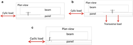
Schemes of the tests. (a) Uniaxial shear test. (b) Biaxial shear test. (c) Uniaxial sliding test
-
Biaxial shear tests (see Fig. 4.40b): The specimens were loaded in two horizontal directions perpendicularly and in parallel with the longitudinal axis of the panel. The hammer-head strap was loaded in shear and tension simultaneously. The hammer head strap was loaded in its strong direction.
-
Uniaxial sliding tests (see Fig. 4.40c): The load was applied in the horizontal direction in parallel to the longitudinal axis of the panel. The channel mounted in the panel was loaded in parallel to its longitudinal axis. The hammer-head strap was loaded perpendicularly to its weak direction. These tests gave information of the response of the sliding connections in the vertical direction.

The hammer-head connection presented in Fig. 4.38a is very common in the construction practice, yet hits behaviour at cyclic loading in the plane of the panel was never tested before. The main phases of the response are summarized in Fig. 4.41. In order to make this presentation clearer, the main steps are explained on the example of the connection loaded only in one direction. This mechanism is activated when the connections are loaded perpendicularly to the strong axis of the strap.

The main steps of the response of connections presented in Fig. 4.38a
In the beginning the strap can rotate without restrictions (a). The displacements of the panel and the rotations of the strap increase simultaneously. When the displacements of the panel are large enough the head of the strap is stacked into the channel. Consequently, the force in the connection is increased (b). Plastic deformations of the head of the strap increase (c). When the displacements are large enough, the gap between the panel and the beam is closed (d). The force almost instantly considerably increases due to the activated friction between the panel and the beam. All these phases are visible in the force-displacements diagram, presented in Fig. 4.4. They are marked by red spots. The strength of connections subjected to cycling loading was considerably smaller than that observed in the monotonic tests.
In connections presented in Fig. 4.38b the failure of the channel mounted in the panel was typically observed. The screw was pulled out from the channel. The same type of the failure was observed in the special connections of the horizontal panels and columns (Fig. 4.38c). In both cases the response was considerably different compared to the connections presented in Fig. 4.38a. The strength was larger, particularly in the connections of the horizontal panels and columns. More details about the response of the tested connections can be found in Isakovic et al. (2013).
4.8 Higher Modes Effects in Multi-Storey Precast Industrial Buildings
Initial research was mostly devoted to single-storey buildings, which are indeed most frequently used. But nowadays, there has been more and more demand for complex multi-storey buildings (Fig. 4.6). The question arises, to what extend the research findings for single-storey buildings can be extended to multi-storey structures? It was found that there are several issues specific to multi-storey buildings. Obviously the columns are higher and loaded with higher compressive axial force. Consequently the margin of overstrength may be lower. The assumption of perfectly hinged connections between the beams and columns leads to models with very slender cantilevers, which might be unrealistic. However, the most specific and important problem is related to the higher modes effect. This can increase the shear forces in columns and first of all the demand on the connections for several times, compared to the values indicated by classical design procedures. If we did not consider this effect properly, the capacity design cannot be done. This problem was identified already in the PRECAST project (Fischinger et al. 2007). Later it was experimentally demonstrated and analytically studied in detail within the SAFECAST project.
Blind predictions of the response of the SAFECAST full-scale structure indicated very important higher mode effect. This was particularly obvious in the case of the prototype 2 (Fig. 4.21b) with hinged beam-to-column connections. The actual test proved that the prediction was correct. The good match of the predicted and experimental results (Fig. 4.42) also proved that the analytical models were efficient.

PSD response of the SAFECAST prototype 2 (Fig. 4.21b) confirmed very large effect of higher modes, which was numerically predicted
Shear magnification factors were systematically studied by inelastic response analyses on five realistic three–storey cantilevered structures, typical for the construction practice in Europe (Fischinger et al. 2011a). The same height of the stories (3.3, 3.2 and 3.2 m) as in the case of the full-scale SAFECAST structure (Fig. 4.20) were assumed. Buildings were modelled as single multi-storey columns. To each of the five buildings/columns different value of the normalized axial force ν d (0.05≤ ν d ≤0.20) was assigned to reflect actual spans and loads used in practice. The buildings were designed according to Eurocode 8, using standard design procedures based on the results of the equivalent elastic spectrum modal analysis (a g,max = 0.25 g and Soil Type B) considering one half of the inertia characteristics of the un-cracked sections. The same reduction as for DCH cast-in-situ frames q = 4.5 was assumed. The response history analyses were performed using OpenSees with a set of accelerograms, matching the EC8 spectrum.
Figure 4.43 shows the shear magnification factor (the ratio between the shear forces obtained by the inelastic analyses and those obtained by the equivalent elastic spectrum modal analysis) for the five investigated structures, identified by their normalized axial force value. For each structure, three different assumptions regarding stiffness of the columns and overstrength were considered in the inelastic response analyses. In the Fig. 4.43 the circles denote results of the model based on the actual stiffness during response (model 1). Squares indicate the results obtained with the inelastic analysis using the bilinear model having the same initial stiffness as it had been used in design (one half of the inertia characteristics based on the un-cracked section were used) – model 2. Model 3 (triangles) is basically the same as the model 2, except for the overstrength, which is not considered.

Shear magnification ratios evaluation for the five analysed structures using different stiffness/overstrength models
The results show that, as expected, shear forces are strongly influenced by the overstrength originating from different sources (including the usual assumptions about initial stiffness). In any case, the actual shear forces in multi storey cantilevered structures are considerably higher than the forces foreseen by the equivalent linear-elastic lateral force analysis, or by the modal response spectrum analysis specified in the codes. Simply said, this magnification occurs due to flexural overstrength and the amplified effect of the higher modes in the inelastic range.
It has been demonstrated that the similar shear magnification factor as proposed in Eurocode 8 for ductile (DCH) RC structural walls can be used also in the case of multi-storey cantilever columns in precast buildings (see Rejec et al. 2012 for definitions and derivation of the formula):
It is important to note that the shear magnification factors for shear forces as large as the behaviour factor q are possible. Shear forces are directly further related to the seismic (storey) forces, which are the inertial forces acting on the floors of a structure and can be calculated as the difference between the total shear force above and below each floor. In precast structures these forces are particularly important as they determine the design of the floor system as well as beam-to-column connections. Therefore the study of the amplifications of the shear forces was extended to seismic storey forces and similar (modified) amplification factors ε were proposed.
4.9 Seismic Collapse Risk of Precast Industrial Buildings
The research, which is described in the previous sections, has provided the models and tools needed for a robust and reliable assessment of seismic risk of the precast industrial buildings. The result of these risk studies have been then of great importance for the calibration of the design requirements proposed for Eurocode 8. The study was done in two phases. First a systematic study of single-storey buildings with strong connections (assuming that the proper capacity design procedure was applied) was done (Kramar et al. 2010a). Then the study was extended to multi-storey structures with strong and weak connections (Fischinger et al. 2012b).
The limit state of the structure was defined as the inability of a system (column) to support gravity loads because of excessive lateral displacement. The collapse capacity of the structure (column) was predicted with the deteriorating numerical model (see Sect. 4.5) considering P-delta effects. The Intensity Measure (IM)-based variation of the recently popular PEER methodology (Fajfar and Krawinkler 2004) was used to estimate the probability of exceeding a structural limit state. The methodology is illustrated in Fig. 4.44.

Schematic of the IM-based approach
It is based on the Incremental Dynamic Analysis (IDA). IDA involves a series of dynamic analyses performed under several values of the intensity. The result is an IDA curve which is a plot of response values (i.e. damage measure – DM) versus the intensity levels (i.e. intensity measure – IM). The collapse of the structure occurs when the DMs increase in an unlimited manner for exceedingly small increments in the IM (collapse is indicated as the black dot on the IDA curve in Fig. 4.44). Considering the record-to-record variability and the uncertainty in the numerical modeling, large number of IDA curves corresponds to the same structure, thus resulting in large number of limit state intensities (S c ). Separate analysis is involved in order to determine the seismic hazard function (H s ). The hazard function is defined as the probability that the intensity of the future earthquake will be greater than or equal to the specific value. Finally, limit state probability is calculated as the hazard function multiplied by the probability density function (PDF) of the limit state intensity and integrated over all values of the intensity. Presuming the lognormal distribution of the limit state intensity and exponential form of the seismic hazard function, limit state probability of the structure can be derived analytically.
The appropriate limit value for the probability of collapse has been proposed based on the recommendations suggested by the Joint Committee on Structural Safety (JCSS 2001). It is important to note that only regular buildings were analysed.
Whereas the uncertainties in the parameters used in the PEER methodology have often been only roughly estimated, a rigorous analysis of the effect of uncertainty in the model parameters on the dispersion of the collapse capacity of the analyzed precast system (columns) was made. The dispersion due to uncertainty in the model parameters was large (conservative estimates vary from 0.18 to 0.33 depending on the column) and of similar size as the usual value of record-to-record variability (0.4 according to ATC). Both methods, the more rigorous Monte Carlo method and the simpler first order method, yielded comparable results.
4.9.1 Seismic Collapse Risk of Single-Storey Precast Industrial Buildings with Strong Connections
The mass of the structure tested within the PRECAST project (the total mass of the prototypes was 57.9 t, which resulted in the average mass of 9.6 t per individual column) was low compared to the mass in the real structures. Therefore a systematic parametric study was done (Kramar et al. 2008) for a whole range of possible average masses in the practical applications (10–150 t, which corresponded to the tributary roof area of 230 m2). The results for the column with the cross-section dimensions 60/60 cm are presented here. Record-to-record variability was considered by means of 50 accelerograms generated to simulate the seismic action according to EC8. The hazard function was derived from the design acceleration values for return periods of 475 (0.25 g), 1,000 (0.3 g) and 10,000 years (0.55 g) for the area of Ljubljana (Kramar 2008; Kramar et al. 2010a).
Two different cases were analysed. In one case EC8 detailing requirements (in particular 1 % minimum longitudinal reinforcement and the minimum code required confinement) for DCH structures were considered. In the other case only the calculated (statically required) reinforcement was taken into account without considering detailing requirements. In this case the resulting amount of the reinforcement was much lower and similar to the reinforcement observed in some existing structures (although seismic force reduction factor 4.5 was used in both cases).
Seismic risk was estimated based on the following criteria. Capacity of the structure was expressed in terms of PGA (PGAC). Reference value (5 % percentile of PGAC) was compared to the design acceleration of 0.25 g. Probability of collapse in 50 years for the area of Ljubljana (HLS,50) was considered. While details are given in Kramar et al. (2010a), the results are summarised in Figs. 4.45 and 4.46.

Seismic risk (EC8 detailing requirements are considered)

Seismic risk (EC8 detailing requirements are not considered)
Minimum EC8 detailing requirements provide the analysed structures with sufficient overstrength so that the seismic risk is acceptably low (the probability of collapse is 0.1–1.2 % in 50 years). However, if only the calculated reinforcement is considered (disregarding the minimum detailing requirements), the conservative estimate of seismic risk is very high (the probability of collapse is 1.0–8.5 % in 50 years). The results have been used to obtain a quantitative evaluation of the force reduction factor used in the Eurocode 8 standard.
4.9.2 Seismic Collapse Risk of Multi-Storey Precast Industrial buildings with Strong and Weak Connections
The analysis described in the previous sub-section was extended to a set of realistic regular multi-storey precast buildings, which are commonly used in the Slovenian/European practice (Fischinger et al. 2012b). The investigated structural system (Fig. 4.47) consisted of 3 multi-storey cantilevers connected with the hinged beams. In accordance with the common practice, the structure had either 2 or 3 floors. The height of the first storey was assumed equal to 7 m, while the height of the subsequent stories was taken equal to 5 m. The amount of mass (i.e. vertical loading) and thus the size of the column cross-sections were varied within the range determined by the Eurocode standards. The structures vary depending on the column cross-section (bxh), and maximum normalized axial force measured at the base of a middle column (ν d ).

Numerical model of multi-storey precast structures
Realising that major seismic risk associated with many existing prefabricated systems is related to the inferior behaviour of connections, realistic strength of the beam-to-column connections as measured during experiments (weak connections) was considered and compared with the results obtained with the assumption of the strong connections.
Some typical results are shown in Figs. 4.48 and 4.49 discussed in the following text.

Median PGA capacity of the structures

Frequency of exceeding the limit state in 50 years
The design of multi-storey cantilever columns in precast structures is governed by drift and slenderness limitations. This study re-confirmed that the resulting cross-sections of the columns are large – in most realistic cases between 60 × 60 and 80 × 80. Taking into account the minimum longitudinal reinforcement requirement (1 %), this results in a considerable overstrength. So the peak ground acceleration capacity for structures with strong connections was frequently (for vd between 0.1 and 0.15) several times higher than the design ground acceleration. Accordingly, the probability of collapse in 50 years was sufficiently low in comparison with the recommended values. In the analysed structures value vd = 0.15 corresponds approximately to the vertical load of 10 kN/m2 acting on a tributary area of 100 m2. Larger loads than this could be considered as rather exceptional. However, for structures carrying such large masses, overstrength is not so pronounced. In these cases, the stiffening of the system by concrete walls/cores or the use of dissipative elements is needed. The same applies, if the designer wants to reduce the large cross-sections of the columns.
Note that the cross-section of the columns in 3-storey structures were larger than in the case of the 2-storey structures (this was mainly due to the drift limitations). Therefore the peak normalized axial force of the 3-storey structures was smaller compared to the 2-storey structures. When comparing the 2-storey and 3-storey structures, columns with the same normalized axial force should be considered. If such comparison is made, it can be concluded that the results are similar for both structures.
It was particularly important to evaluate the influence of the realistic (weak) connections on the seismic risk. For structures with lower masses (vd from 0.1 to 0.15) the risk did not increase compared to the risk assessed in the case of structures with strong connections (indicated that the strength of standard connections was sufficient). However, in structures with larger masses the connections were damaged and the risk drastically increased. This confirms the conclusion that the capacity design of connections is strictly needed. According to these results, beam-column connection with median capacity of 165 kN (this have been experimentally determined value for the connections typically used in the design practice) should only be used for the structures where vd does not exceed approximately 0.15. In other cases stronger connections should be used or structural walls should be used to strengthen the system. In general, this results demonstrate that beam-column connections cannot dissipate a large amount of the energy introduced by the seismic loading. Soon after the yielding occurs, the failure of the connections follows, resulting in high seismic risk.
4.10 Eurocode 8 Implications
The key result of the presented projects has been a set of proposed improvements (either proposed or already incorporated) of the relevant requirements in Eurocode 8. Among many contributions, the most important are:
-
The calibration of the behaviour factor;
-
The proposed designed methodology for the design of the typical connections in precast industrial buildings (Negro and Toniolo 2012) based on the experimentally verified capacity of the connections (see Sect. 4.5)
-
The proposed methodology for the realistic evaluation of the demand in the multi-storey columns in precast industrial buildings (see Sect. 4.8)
-
The proposal of many innovative solutions in precast construction (not discussed in this contribution)
-
Systematic risk evaluation supporting the design recommendations (see Sect. 4.9)
-
The evaluation of the capacity of the cladding-to-structure connections and the on-going research on the methodology of the design, which would explicitly account for the cladding contribution (see Sect. 4.7)
While most of these results were already discussed in the previous sections, additional and more detailed comments on the choice of the behaviour factor are given in this section.
Behaviour factor is a semi-empirical parameter, which reflects many partial factors. Some of them can be experimentally or analytically calibrated, yet another, like those reflecting local construction practices, are almost impossible to consider with rigorous approach and require a good deal of engineering feeling. In particular in a complex structural system composed of many details and components of extremely different ductility, it is an illusion to give a precise value for the behaviour factor valid for all different systems. Nevertheless, the results of the presented research projects have contributed a lot towards better understanding of the energy dissipation capacity the precast industrial buildings and the definition of the behaviour factor.
Considering the above mentioned ambiguities and the lack of relevant knowledge as well as mixed field observations, one can understand that the value of the behaviour factor was changing dramatically during the evolution of the Eurocode 8.
Before Eurocode standards were introduced, most designers used the same value of seismic forces for cast-in-situ frames and precast structures. Therefore a specific note in the paragraph B1.2(2) of (CEN 1995) “Single storey industrial buildings with doubly hinged beams should be distinguished from the normal frame system” came as a shock. Strictly applying the standard one-storey precast industrial structures should be designed as inverted pendulum structures (the structural system is a set of cantilevers and more than 50 % of the mass is concentrated at the top of the cantilevers). This requirement practically meant that precast industrial structures should be designed for elastic response. However, (CEN 1995) explicitly allowed in paragraph B3.2(3) that q0 = 3 can be used for precast columns in single-storey industrial buildings, which are not integrated into frames under the following conditions: (a) the top of the columns are connected with ties along both principal directions of the building and (b) the number of columns is at least six. This value was predominantly based on the engineering judgment and compromise. The ambiguity of the topic was further stressed by the fact that Annex B, which covered seismic design of precast structures, was only informative. In any case, there was not explicit reference to multi-storey structures.
The authors believe that considering the limited level of the information available at that time and the risk of the catastrophes with most damaging consequences, the proposals in CEN (1995) were fully justified. However, it was also clear that in many cases they were very conservative and they were jeopardizing (without proper research evidence) the competitiveness of a large sector of construction industry. In addition field evidence showed quite good behaviour of precast industrial buildings in spite of the fact that they were typically designed with the same behaviour factor as the cast-in-situ structure would be. Moreover, making the columns unnecessary strong would increase the demand on the most vulnerable components of the structural system – connections, and it might have a contra-productive effect.
Therefore the extensive research, presented in this paper, was initiated (Sect. 4.4). Based on the results of the ECOLEADER project a very important change was incorporated into the final pre-standard (CEN 2003 – prEN 1998-1-2003) and subsequently into the standard valid today (CEN 2004). A note was added to the definition of the “inverted pendulum structure”, saying that “One-storey frames with column tops connected along both main directions of the building and with the value of the column normalized axial load vd nowhere exceeding 0.3, do not belong to this category”. This note was included (as explained by the author – Professor Toniolo) with the purpose to define precast industrial buildings as “frames” and consequently allowing to use the same behaviour factor for precast industrial buildings and cast-in-situ frame systems. This change might not be identified and understood at the first sight, since it is not a part of the chapter 5.11 (Precast concrete structures), but appears only as a note within the definitions of the structural systems and there is no explicit statement that such systems are frame systems.
In fact, in spite of the experimental results of the ECOLEADER project and the extensive supporting analytical studies, the proof for this very important change was not conclusive. First (as discussed in Sect. 4.4.2) ECOLEADER proved only that one-storey precast industrial building behaved similar (even better) than the one-storey cast-in-situ frame with strong beam. This is not to say that such cast-in-situ frame has the same energy dissipation as the multi-storey, multi-bay frame designed by a weak beam – strong column concept. Moreover, this is certainly not the case. Additionally, it should be considered that some important simplifications were used in the experiment and analyses (strong beam-to-column connections, rigid diaphragm, regular building, and construction in the controlled environment). Therefore it was obvious that further research effort is urgently needed to verify this important decision better.
PRECAST structure demonstrated (see Sect. 4.9 on risk analyses) that it is feasible to use such high behaviour factors, but with the condition that the drift limitations and minimum reinforcement requirements are fully respected. There were several factors contributing to the demonstrated good behaviour: (a) typical low compressive axial force in the columns of the single-storey buildings; (b) inherent overstrength due to the drift and slenderness limitations as well as minimum reinforcement; (c) confinement at the base of the columns (however, ASSOBETON tests indicated that the maximum spacing of the transverse should be even shorter than those required at the present by EC8). And first of all, the beam-to-column connections used in the existing practice should be designed by using capacity design rules.
Finally, after the careful study and analyses the authors are now convinced that all the debate about the behaviour factor has not been that important. What typically determines the response of the structure, is the inherent overstrength imposed by drift and slenderness limitations and not the strength determined by the behaviour factor. Of course practically elastic design (as required in the earliest stages of the pre-standard) was demonstrated as overly conservative and in some cases even contra productive. But on the other hand, there is practically no need to insist on the use of the same behaviour factor for industrial buildings and cast-in-situ frames (based on weak beam – strong column concept). One might argue that the columns themselves exhibit the ductility of more than four. But it should be considered that the drifts (up to 10 %) and top displacements (up to 1 m) needed to exploit this energy dissipation capacity of the column are impractical to achieve.
SAFECAST project brought additional research evidence for the multi-storey buildings (they were never studied before and there has been no explicit requirements for these structures in EC8) and for structures with realistic connections. The experiment at ELSA showed good behaviour of the 3-storey structure designed by q = 4.5. However, the mass was, in spite of the large specimen, still small compared to realistic structures. The systematic risk study (Sect. 4.9.2) showed that the use of the behaviour factor 4.5 for the DCH structure was fine. But again, the stiffness and strength were dictated by the drift and slenderness limitations rather than by the behaviour factor.
4.11 Conclusions
Not to repeat again all the specific and detailed conclusions given in the individual sections of this report, only the overall understanding of the seismic response of the precast industrial buildings, which the authors obtained during many years of the study, is presented and summarized in the conclusions.
-
1.
When we refer to a precast system, we shall clearly and carefully determine all the details (in particular the connections and ties) of the system. Generalization can be incorrect and dangerous since even seemingly minor differences can change the behaviour considerably. Therefore since 1981 the Slovenian (former Yugoslav) code (…) required (Article 39 and 44) that the prototypes of prefabricated buildings or structures which are produced industrially in large series (except for wooden structures) and which are designed in zones of seismic activity VIII or IX, shall be checked experimentally and by inelastic dynamic analyses. While at the present, there is no such explicit requirement in the Eurocode 8, it was sensibly considered in the Design guidelines for connections of precast structures under seismic actions (Negro and Toniolo 2012).
-
2.
Such verification was fully accomplished for the structural system of the precast industrial buildings with dowel beam-to-column connections, which is discussed in this paper and which is very frequently used in Europe. Unprecedented experimental, numerical and risk studies were done.
-
3.
The authors are convinced that such structural system can be designed as safe in the seismic regions if all Eurocode requirements and research recommendations described in this paper are considered. This in particular includes drift limitations and capacity design of the key connections in the system.
-
4.
The document Design guidelines for connections of precast structures under seismic actions (Negro and Toniolo 2012), produced within the SAFECAST project, provides a valuable tool for this purpose.
-
5.
Among many different connections in the system, the beam-to-column dowel connection was particularly well studied. The capacity of the connections at large relative rotations between the column and beam were investigated. The behaviour of this connection is now fully understood and the design formulas and the design methodology are provided. Note that the design procedure for the connection with the dowels close to the edge of the column was recently improved (Zoubek et al. 2014a, b) and considerably modified in comparison with the formulas given in the Design guidelines.
-
6.
Innovative (i.e. dissipative) connections and new structural solutions were studied within the presented research projects. However, this paper is restricted to the traditional existing systems (due to the rights and patents of the industrial partners as well as due to the limitation of the length of the paper).
-
7.
Multi-storey structures were extensively studied in addition to the single-storey structure. Several additional problems were identified. Most important is the problem of higher modes effect, which highly increases the demand for the connections and for the shear resistance of columns. Magnification factors for shear and seismic storey forces were proposed.
-
8.
Drift limitations require very large dimensions of the columns in the multi-storey system using dowel (hinged) beam-to-column connection. While also multi-storey building can be safely designed in seismic regions, it is a general impression that multi-storey structures need some kind of stiffening, either in the form of additional cores (the connections of the core to the precast system should be carefully designed!) or (semi) rigid beam-to-column connections. Other promising solution is the use of energy-dissipating devices.
-
9.
Effective numerical models were proposed, including the refined FEM models to describe the complex response of the dowel connection and macro models of the post-critical behaviour of the slender columns with very high shear-span ratio.
-
10.
Cladding-to-structure connections were very poorly understood in the past. The authors realized that for decades we have been using in design the model, which is not correct. Using existing connections, cladding cannot be fully separated from the structure during strong earthquakes. The interaction between the cladding panels and the columns should preclude large displacement, which are needed to justify the energy dissipation capacity (behaviour factors) assumed in the design. Complex realistic interaction is still under investigation within the SAFECLADDING project.
-
11.
Finally, it should be noted that all presented research was restricted to regular structures.
References
Arslan MH, Korkmaz HH, Gulay DG (2006) Damage and failure pattern of prefabricated structures after major earthquakes in Turkey and shortfalls of the Turkish Earthquake code. Eng Fail Anal 13(4):537–557
ATC-08 (1981) Proceedings of a workshop on design of prefabricated concrete buildings for earthquake loads. ATC, NSF, Redwood City, California, USA
Biondini F, Toniolo G (2002) Probabilistic calibration of behaviour factors of EC8 for cast-in-situ and precast frames. In: 17th BIBM Congress, Istanbul
Biondini F, Toniolo G (2004) Validation of seismic design criteria for concrete frames based on Monte Carlo simulation and full scale pseudodynamic tests. In: 13th WCEE, Vancouver
Bournas A, Negro P, Taucer FT (2013a) Performance of industrial buildings during the Emilia earthquakes in Northern Italy and recommendations for their strengthening. Bull Earthq Eng, published on-line, June 2013
Bournas A, Negro P, Molina FJ (2013b) Pseudodynamic tests on a full-scale 3-storey precast concrete building: behavior of the mechanical connections and floor diaphragms. Eng Struct 57:609–627
CEN (1995) Eurocode 8 – Design provisions of earthquake resistance of structures, part 1–3: specific rules for various materials and elements, ENV 1998-1-3:1995. European Committee for Standardization, Brussels
CEN (2003) Eurocode 8: design of structures for earthquake resistance – part 1: general rules, seismic actions and rules for buildings, prEN 1998–1, Draft No. 6, version for translation (Stage 49). European Committee for Standardization, Brussels
CEN (2004) Eurocode 8: design of structures for earthquake resistance – part 1: general rules, seismic actions and rules for buildings, EN 1998–1. European Committee for Standardization, Brussels
CEN/TS 1992-1-1 (2005) Design of fastenings for use in concrete – part 4–2: headed fasteners, 89/106/EEC, European Comittee for Standardization, Brussels
Dulascska H (1972) Dowel action of reinforcement crossing cracks in concrete. JACI 69–70:754–757
EERI (1979) Friuly, Italy earthquakes of 1976. Earthquake Engineering Research Institute, Oakland, California, USA
EERI (1989) Armenia earthquake reconnaissance report. Earthq Spectra supplement, Oakland, California, USA
EERI (2000) Kocaeli, Turkey, Earthquake of August 17, 1999. Earthq Spectra supplement, Oakland, California, USA
Engström B (1990) Combined effects of dowel action and friction in bolted connections. Nordic Concrete Research, The Nordic Concrete Federation, Publication no. 9, Oslo 1990, pp 14–33
Fajfar P, Krawinkler H (eds) (2004) Performance-based seismic design concepts and implementation. In: Proceedings of an International Workshop, PEER, University of California, Berkeley
Fajfar P, Banovec J, Saje F (1978) Behaviour of prefabricated industrial building in Breginj during the Friuli earthquake. In: 6th ECEE, Dubrovnik, vol 2. pp 493–500
Fajfar P, Duhovnik J, Reflak J, Fischinger M, Breška Z (1981) The behaviour of buildings and other structures during the earthquakes of 1979 in Montenegro, IKPIR publication 19A, University of Ljubljana, Ljubljana
Ferrara L, Colombo A, Negro P, Toniolo G (2004) Precast vs. cast-in-situ reinforced concrete industrial buildings under earthquake loading: an assessment via pseudodynamic tests. In: 13th WCEE, Vancouver, Canada
FIB (2003) Seismic design of precast concrete building structures, Federation International du Beton, Lausanne, Bulletin 27
Fischinger M, Kramar M, Isaković T, Kante P (2007) Seismic behaviour of precast concrete structures with respect to EC8, final report on the contribution of the University of Ljublajana, Chapter 5: two-storey precast industrial building, University of Ljubljana, Ljubljana, pp 51–78
Fischinger M, Kramar M, Isaković T (2008) Cyclic response of slender RC columns typical of precast industrial buildings. Bull Earthq Eng 6(3):519–534, http://www.springerlink.com/content/m282220243851270/fulltext.pdf
Fischinger M, Ercolino M, Kramar M, Petrone C, Isaković T (2011a) Inelastic sesmic shear in multi-storey cantilever columns. COMPDYN 2011, Corfu, Greece, 10 p
Fischinger M, Kramar M, Isaković T (2011b) Inelastic seismic response of precast industrial buildings – research in support of EC8. MASE 14. Maced Assoc Struct Eng 1:39–50
Fischinger M, Zoubek B, Kramar M, Isaković T (2012a) Cyclic response of dowel connections in precast structures. In: 15th WCEE, Lisbon, 10 p
Fischinger M, Kramar M, Isaković T (2012b) Seismic risk assessment of multi-storey precast structures. In: 15th WCEE, Lisbon, 10 p
Fischinger M, Zoubek B, Isaković T (2013) Seismic behaviour of the beam-to-column dowel connections – macro modelling. COMPDYN 2013, Kos Island, Greece, 8 p
Fuchs W, Eligehausen R, Breen JE (1995) Concrete capacity design (CCD) approach for fastening to concrete. ACI Struct J 92(1):73–94
Haselton CB (2006) Assessing seismic collapse safety of modern reinforced concrete moment frame buildings. Dissertation, Stanford University, Stanford, California
Hojlund-Rasmussen B (1963) Betoninstobe tvaerbelastade boltes og dornesbaereevne (Resistance of embedded bolts and dowels loaded in shear). Byngninsstatiske Meddelser, Copenhagen, p 34
Ibarra LF, Medina RA, Krawinkler H (2005) Hysteretic models that incorporate strength and stiffness deterioration. Earthq Eng Struct Dyn 34(12):1489–1511
Isaković T, Zoubek B, Lopatoč J, Urbas M, Fischinger M (2013) Report and card files on the tests performed on existing connections. Deliverable 1.2, SAFECLADDING, University of Ljubljana, Ljubljana
JCSS (2001) Probabilistic model code, part 1: basis of design, 12th draft. Joint Committee on Structural Safety, Lyngby, Denmark
Kramar M (2008) Seismic vulnerability of the precast reinforced concrete structures. Ph.D. thesis (in Slovenian) University of Ljubljana, Ljubljana
Kramar M, Isaković T, Fischinger M (2008) Seismic collapse safety of RC columns in precast industrial buildings. In: 14th WCEE, Beijing, 8 p
Kramar M, Isaković T, Fischinger M (2010a) Seismic collapse risk of precast industrial buildings with strong connections. Earthq Eng Struct Dyn 39(8):847–868, http://onlinelibrary.wiley.com/doi/10.1002/eqe.970/pdf
Kramar M, Isaković T, Fischinger M (2010b) Experimental investigation of “pinned” beam-to-column connections in precast industrial buildings. In: 14th ECEE, Ohrid, 8 p
Negro P, Toniolo G (2012) Design guidelines for connections of precast structures under seismic actions. Publication Office of the European Union, Luxemburg
Negro P, Bournas D, Molina FJ (2013) Pseudodynamic tests on a full-scale 3-storey precast concrete building: global response. Elsevier Eng Struct J 57:594–608
Panagiotakos TB, Fardis MN (2001) Deformations of reinforced concrete members at yielding and ultimate. ACI Struct J 98(2):135–148
PEER Structural Performance Database (2007) Pacific earthquake engineering research center. University of California, Berkeley, http://nisee.berkeley.edu/spd
Priestley MJN (1996) The PRESS program: current status and proposed plans for phase III. PCI J 41:22–40
Psycharis IN, Mouzakis HP (2012) Shear resistance of pinned connections of precast members to monotonic and cyclic loading. Eng Struct 41:413–427
Rejec K, Isaković T, Fischinger M (2012) Seismic shear force magnification in RC cantilever structural walls, designed according to Eurocode 8. Bull Earthq Eng 10(2):567–586
Saatcioglu M, Mitchell D, Tinawi R, Gardner NJ, Gillies AG, Ghobarah A, Anderson DL, Lau D (2001) TheAugust 17, 1999 Kocaeli (Turkey) earthquake-damage to structures. Can J Civ Eng 28(8):715–773
Saisi A, Toniolo G (1998) Precast RC columns under cyclic loading: an experimental programme oriented to EC8. Studi e ricerche, Scuola di specializzazione. Politecnico di Milano, vol. 19, pp 373–414
Shiohara H, Watanabe F (2000) The Japan PRESS precast concrete connection design. In: 12th WCEE, Aukland
Toniolo G (2012) European research on seismic behaviour of precast structures. In: 2012 NZSEE conference, Lausanne, Switzerland
Toniolo G (coordinator) (2007) Final report of the EU Research Project: seismic behaviour of precast concrete structures with respect to EC8 (Contract No. G6RD-CT-2002-00857), Brussels
Toniolo G, Colombo A (2012) Precast concrete structures: the lessons learned from the L’Aquila earthquake. Struct Concr 13:73–83
Tzenov L, Sotirov L, Boncheva P (1978) Study of some damaged industrial buildings due to Vrancea earthquake. In: 6th ECEE Dubrovnik, vol 6. pp 59–65
UNDP/UNIDO (1985) Building construction under seismic conditions in the Balkan region. UNDP/UNIDO Project RER/79/015, vol 2: design and construction of prefabricated reinforced concrete building systems, Vienna Austria; Skopje Macedonia
Vintzeleou EN, Tassios TP (1986) Mathematical model for dowel action under monotonic and cyclic conditions. Mag Concr Res 38:13–22
Vintzeleou EN, Tassios TP (1987) Behaviour of dowels under cyclic deformations. ACI Struct J 84(1):18–30
Zoubek B, Fischinger M, Isaković T (2013a) Seismic behaviour of the beam-to-column dowel connections – FEM analysis. COMPDYN 2013, Kos Island, Greece, 8 p
Zoubek B, Isaković T, Fahjan Y, Fischinger M (2013b) Cyclic failure analysis of the beam-to-column dowel connections in precast industrial buildings. Eng Struct 52:179–191
Zoubek B, Fischinger M, Isaković T (2014a) Estimation of the cyclic capacity of beam-to-column dowel connections in precast industrial buildings. Submitted for possible publication in Bulletin of Earthquake Engineering, Springer, Netherlands
Zoubek B, Fischinger M, Isaković T (2014b) Seismic response of dowel connections in precast industrial buildings, Second European conference on earthquake engineering and seismology, Istanbul, 25–29 August 2014
Acknowledgements
The presented research was mainly supported by the three large EU projects: (a) PRECAST project (Grant agreement no. G6RD-CT-2002-00857) – “Seismic Behaviour of Precast Concrete Structure with respect to EC8” in the Fifth Framework Programme (FP5) of the European Commission, (b) SAFECAST project “Performance of Innovative Mechanical Connections in Precast Building Structures under Seismic Conditions” (Grant agreement no. 218417–2), and (c) SAFECLADDING project – “Improved Fastening systems of Cladding Wall Panels of Precast Buildings in Seismic Zones” (Grant agreement no. 314122), both in the Seventh Framework Programme (FP7) of the European Commission. All projects were led by the associations of the precast producers in Europe and the Politecnico di Milano. The leading persons in this research were in particular Professor Giandomenico Toniolo and Dr. Antonella Colombo. The large scale experiments were performed at the ELSA European Laboratory for Structural Assessment of the Joint Research Centre of the European Commission at Ispra (Italy) along with numerous experiments and numerical studies done at the Istanbul Technical University, National Laboratory for Civil Engineering in Lisbon, National Technical University of Athens Polytechnic University of Milan, the Slovenian National Building and Civil Engineering Institute (ZAG), and University of Ljubljana. The work was further supported by the Ministry of Higher Education, Science and Technology of Slovenia. During the time of this long-going research many post-graduate students and post-doc researchers contributed to the results of the research group in Ljubljana. The authors are in particular grateful to Dr. Miha Kramar for his outstanding contributions. The authors are also obliged to Professor Giandomenico Toniolo and Dr. Paolo Negro, who contributed valuable material, which was used in the introductory sections of this paper.
The research results were always discussed between the members of the consortia of the above-mentioned research projects and general agreement was found in most cases. Nevertheless, it is obvious that the conclusions of such complex research cannot be exactly defined and they cannot be always supported by all the partners. Therefore the views and the conclusions in this paper are solely those of the authors, although the paper was in general approved by all the partners.
Author information
Authors and Affiliations
Corresponding author
Editor information
Editors and Affiliations
Rights and permissions
This chapter is published under an open access license. Please check the 'Copyright Information' section either on this page or in the PDF for details of this license and what re-use is permitted. If your intended use exceeds what is permitted by the license or if you are unable to locate the licence and re-use information, please contact the Rights and Permissions team.
Copyright information
© 2014 The Author(s)
About this chapter
Cite this chapter
Fischinger, M., Zoubek, B., Isaković, T. (2014). Seismic Response of Precast Industrial Buildings. In: Ansal, A. (eds) Perspectives on European Earthquake Engineering and Seismology. Geotechnical, Geological and Earthquake Engineering, vol 34. Springer, Cham. https://doi.org/10.1007/978-3-319-07118-3_4
Download citation
DOI: https://doi.org/10.1007/978-3-319-07118-3_4
Published:
Publisher Name: Springer, Cham
Print ISBN: 978-3-319-07117-6
Online ISBN: 978-3-319-07118-3
eBook Packages: Earth and Environmental ScienceEarth and Environmental Science (R0)